
SCHLAGE AD-200/AD-201 Offline Lock User Guide
Instructions for AD-Series offline locks
Overview
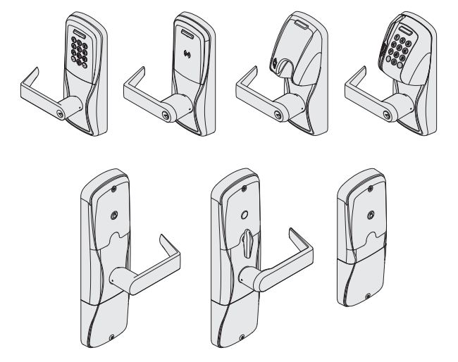
The Schlage AD-200/AD-201 is an off-line electronic lock in the AD-Series product line.
The Schlage AD-201 is a FIPS-201-1 certified off-line electronic lock.
- May be powered by batteries or connected to external power using a UL294 or ULC-S318/ULC-S319 listed power supply capable of sourcing at least 250 mA @ 12 or 24 VDC. See Batteries on page 17, or External power supply on page 18 for more information.
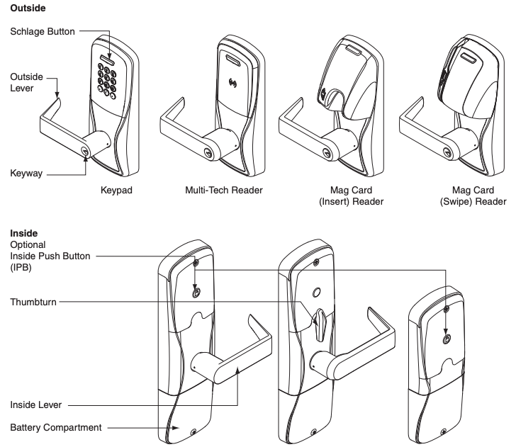
- Outside lever is normally locked.
- Inside lever always allows egress.
- The lock maintains an audit trail of events.
- Configured using the Schlage Utility Software (SUS).
Additional AD-200 reader options: Mag + Keypad, Multi-Tech + Keypad AD-200-MD
Note: Proximity card (PR, PRK) ONLY and Smart card (SM, SMK) ONLY readers have been discontinued and replaced by the Multi-Tech (MT, MTK) readers that provide all the same functionality as the original Proximity and Smart card readers in a single credential reader. The AD-201 reader is a FIPS-201-1 certified Multi-Tech + Keypad (FMK) reader.
This product is compliant of UL294 and ULC-S319 standard. This product’s compliance would be invalidated through the use of any add-on, expansion, memory or other module that has not yet been evaluated for compatibility for use with this UL Listed product, in accordance with the requirements of the Standards UL294 and ULC-S319. This product has been evaluated for CAN/ULC-S319 Class 1.
UL294 Access Control Levels tested to: Destructive Attack – Level 1; Line Security – Level 1; Endurance – Level 4; Standby Power – Level 1.
Lock functions
The AD-200/AD-201 is available in one of four functions:
Privacy (40): Lockset is normally secure. Pressing the Inside Push Button or extending the deadbolt will disable normal electronic access from the outside. Opening the door, retracting the deadbolt or pressing the Inside Push Button a second time deactivates the privacy status.
Office (50): Lockset is normally secure. Inside Push Button may be used to select passage or secured status.
Apartment (60): Lockset is normally secure. Inside Push Button is used to select passage or secure status. While in the secure state, opening the door or pressing the Inside Push Button causes the lockset to toggle unsecured. The door must be closed and a valid credential presented to secure the lockset from the outside.
Classroom/Storeroom (70): Lockset is normally secure. Valid toggle credentials may be used to change to a passage or secure status.
Getting started
Follow these steps when setting up a new lock.
- Install the lock. See the installation guide that came with the lock, or visit www.allegion.com/us for more information.
- Make sure the batteries are installed properly. See Batteries on page 17 for instructions.
- Configure the master construction credential (where applicable). See Construction access mode on page 5 for more information. The lock should remain in construction access mode until you are ready to set up the rest of the system.
- Test the lock for proper mechanical and electronic operation. See Test lock operation on page 14 for more information.
- When ready to set up for normal use, program the user credentials. See Credential types and functions on page 6.
 Programming the lock with the SUS will remove all credentials that were added using the master construction credential.
 - Consult the SUS user guide for information about configuring the lock.
- Familiarize yourself with the information in this guide.
Save this user guide for future reference.
Schlage Utility Software (SUS)
The Schlage Utility Software is used for programming and setup only.
The SUS is used to configure locks. This includes transferring data files between the access control software and locks. For information about the SUS, refer to the SUS user guide.
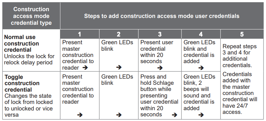
Construction access mode
Construction access mode is used to allow access before the lock has been programmed, and for testing purposes.
- Enabled by default.
- The lock will remain in construction access mode until the mode is cancelled as described below.
- No audits are captured while lock is in construction access mode.
- Use the same master construction credential for all the locks in the facility.
- If you present the first card to a new lock to create the master construction credential and the card is not accepted, the lock has either been programmed or already has a master construction credential.
- If the master construction credential cannot be located, or to put the lock back into construction access mode, reset the lock to factory settings (see page 16 for details).
Locks with keypads – Construction access mode
In the factory default state, locks with keypads have a default PIN of 13579 and “#”, which can be used for installation, testing and construction access. To test, enter default PIN. The Schlage button will blink and the lock will unlock.
The default PIN, 13579 and “#” is automatically deleted when a construction access user credential is added to the lock, or a new programming credential is created, or the lock is programmed with the SUS.
Locks with card readers – Create a master construction credential
The master construction credential is used to program construction access mode credentials.
To create a master construction credential:
- Press and hold the Schlage button while presenting a credential.
- The Schlage button will blink green on the left and right as confirmation.
- Use this card to add construction access mode user credentials.
![]() The master construction credential will not grant access. It is used only to add additional credentials.
The master construction credential will not grant access. It is used only to add additional credentials.
Locks with card readers – Add construction access mode user credentials
Cancel construction access mode
Do one of the following:
- Program the lock with the SUS. See the SUS user guide for more information.
- Reset the lock to factory settings. See Reset to factory defaults on page 16 for more information.
When construction mode is cancelled, the master construction credential and all other credentials added using the master construction credential will no longer function.
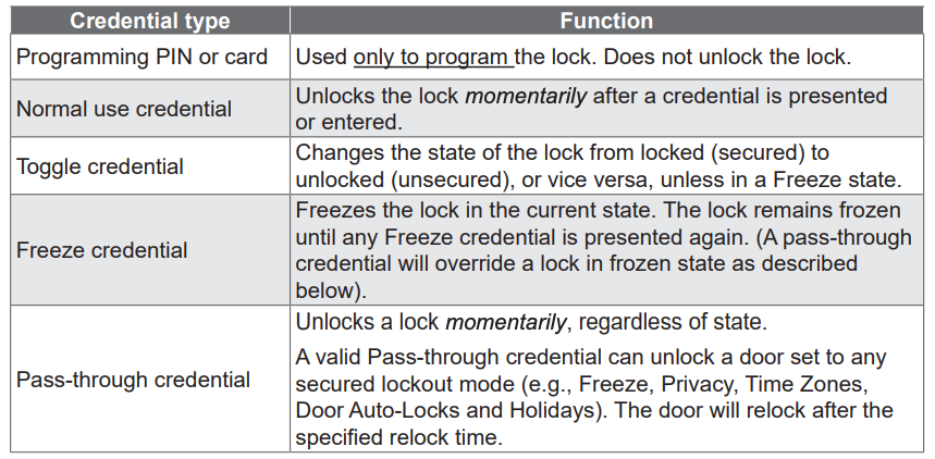
Credential types and functions
Programming credential: A card or 5 digit code used only for lock programming.
Card or PIN credentials: A card that is presented, or a 3-6 digit code entered on the keypad.
Card ID number: When adding any new card credential, a 3-6 digit code is entered prior to presenting the card. This code becomes the Card ID Number. This number can be used to delete a card credential without physically having the card. Keep a log of all Card ID Numbers for future reference.
Note: A unique credential must be used for each credential type described below (for example, a single credential may not be used for both normal use and toggle functions).
Credential forms
Normal, toggle, freeze and pass-through credential types are used in one of three forms:
PIN credential – a 3-6 digit code entered on the keypad.CARD credential – a card presented to the lock.CARD + Card ID Number credential – a card (with a unique Card ID number) presented to the lock. (See a description of Card ID number above for more information.)
Steps for designating each form are in the Manual programming instructions on the following pages.
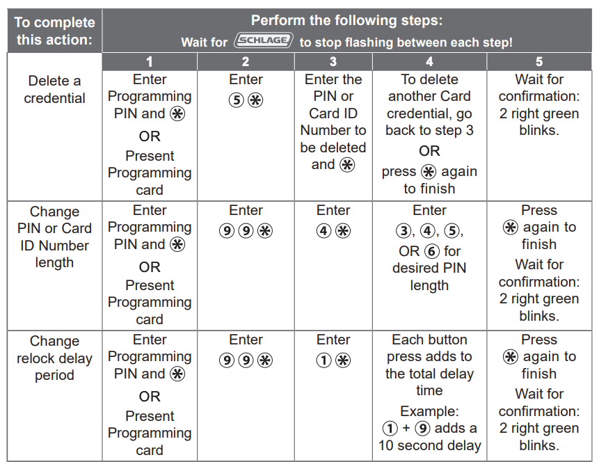
Manual programming instructions
Important notes:
![]() Wait for the Schlage button LEDs to stop flashing before continuing to the next step.
Wait for the Schlage button LEDs to stop flashing before continuing to the next step.
![]() Programming mode will time out if no entry is made in 20-25 seconds. Time out is indicated by three left and nine right red blinks of the Schlage button.
Programming mode will time out if no entry is made in 20-25 seconds. Time out is indicated by three left and nine right red blinks of the Schlage button.
![]() An incorrect entry is indicated by a solid red left and blinking green right LED on the Schlage button. Refer to Error codes on page 13 to interpret error code patterns.
An incorrect entry is indicated by a solid red left and blinking green right LED on the Schlage button. Refer to Error codes on page 13 to interpret error code patterns.
![]() A unique credential must be used for each credential type (for example, a single credential may not be used for both normal use and toggle functions).
A unique credential must be used for each credential type (for example, a single credential may not be used for both normal use and toggle functions).
PROGRAMMING credentials
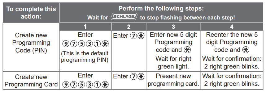
![]() Note: Before creating any credential in the following steps, determine which credential form is desired (see Credential forms on page 6).
Note: Before creating any credential in the following steps, determine which credential form is desired (see Credential forms on page 6).
NORMAL USE credentials
Note: Until a new Normal Use PIN is created, the default PIN is ![]()
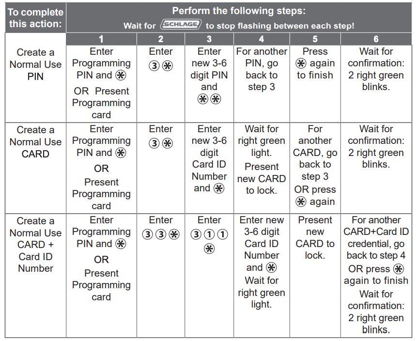
![]() Note: Before creating any credential in the following steps, determine which credential form is desired (see Credential forms on page 6).
Note: Before creating any credential in the following steps, determine which credential form is desired (see Credential forms on page 6).
TOGGLE credentials

![]() Note: Before creating any credential in the following steps, determine which credential form is desired (see Credential forms on page 6).
Note: Before creating any credential in the following steps, determine which credential form is desired (see Credential forms on page 6).
FREEZE credentials
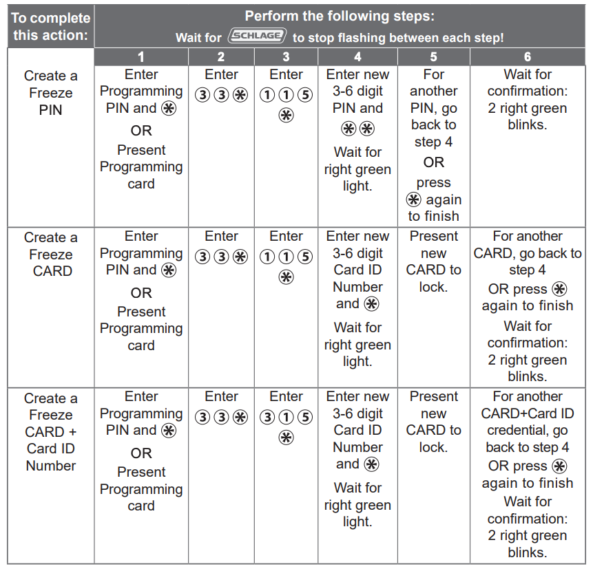
![]() Note: Before creating any credential in the following steps, determine which credential form is desired (see Credential forms on page 6).
Note: Before creating any credential in the following steps, determine which credential form is desired (see Credential forms on page 6).
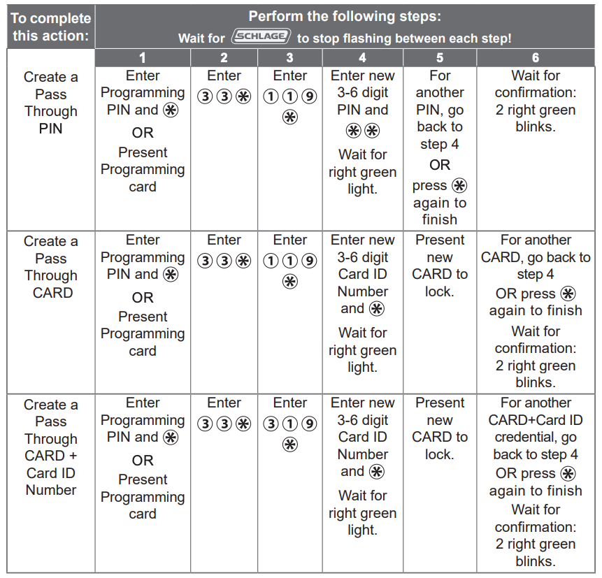
PASS THROUGH credentials
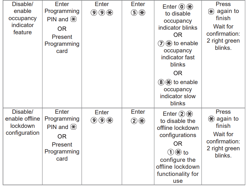
OTHER programming
Error codes
![]() All error codes are indicated on the Schlage button by a solid red left LED, and a blinking green right LED. The number of green blinks indicates the error code.
All error codes are indicated on the Schlage button by a solid red left LED, and a blinking green right LED. The number of green blinks indicates the error code.

Test lock operation
If you encounter problems while performing any of the following tests, review the installation guide and correct any problems.
Mechanical test
- Rotate the inside lever. Operation should be smooth, and the latch should retract.
- Insert the key into the keyway and rotate the key or the key and lever to open the door. Operation should be smooth, and the latch should retract.
Electronic test
Test the AD-200/AD-201 in factory default mode
- For locks with a keypad, press any number key. The lock will beep.
- Press the Schlage button. The keypad should light blue for a few seconds.
- For locks with a card reader, present a credential to the reader. The lock will beep and the left side of the Schlage button will blink red one time. When the lock is in factory default mode, no credentials are accepted.
- In the factory default state, locks with keypads, with or without additional credentials, have a default PIN of 13579 and “#”. To test, enter the default PIN. The Schlage button will blink and the lock will unlock.
Test the AD-200/AD-201 in construction access mode
- When the master construction credential is presented, the lock will beep and the Schlage button will light green for 20 seconds awaiting the presentation of another credential to be granted Construction User Access.
- When a valid construction access user credential is presented, the lock will unlock for the re-latch delay period (default three seconds), and the left side of the Schlage button will blink green. When the lock relocks after the relock delay period, the left side of the Schlage button will blink red.
- If an invalid construction access user credential is presented, the lock will beep and the left side of the Schlage button will blink red one time. For more information, see Construction access mode on page 5.
![]() NOTE: Construction access mode is cancelled when the lock is reset to factory defaults. When construction access mode is cancelled, the master construction credential and all other credentials added using the master construction credential will no longer function.
NOTE: Construction access mode is cancelled when the lock is reset to factory defaults. When construction access mode is cancelled, the master construction credential and all other credentials added using the master construction credential will no longer function.
Normal lock operation
After credentials have been programmed, present credentials to operate the lock as follows:
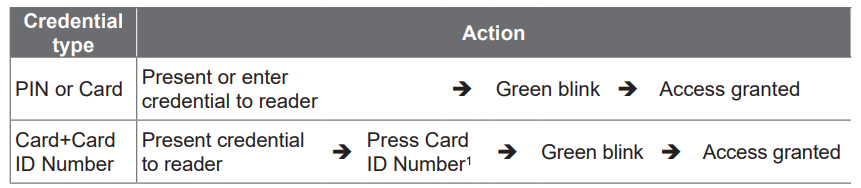
- The default PIN/Card ID length is six digits. The “#” key must be used as an ENTER key for PINs/Card IDs with fewer than six digits. PIN/Card ID length can be manually configured (refer to Change PIN or Card ID Number length on page 12).
Wired remote release feature
System and hardware requirements
- Available on AD-200/AD-201 storeroom function only
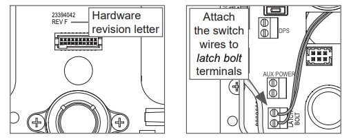
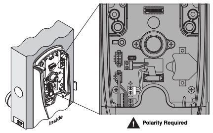
- Compatible with AD-200/AD-201 hardware revision F or higher. See illustration below to locate revision letter on main printed circuit board.
- The AD-200/AD-201 must be programmed with AD-200/AD-201 version 2.45.1 firmware or higher.
Switch specifications, wire specifications and routing
- Recommended switch: basic SPST (single-pole single-throw) momentary action switch with normally open contact configuration.
- Wire gauge AWG 24, stranded, twisted pair, shielded (shield may be left unterminated).
- Belden 9841 or equivalent.
- Maximum cable length is 1000 feet (305 meters).
- Route wires from the switch, through the door frame and door to the latch bolt terminals as shown below.
Wired remote release operation
IMPORTANT! The remote release feature will function only when the AD-200/AD-201 inside cover is completely and properly installed.
Operation with firmware version 2.45.1
- When the remote release button is pressed the lock will unlock for the programmed relock delay period. The Schlage LEDs will flash green once to indicate the lock is unlocked. The beeper will not sound.
- After the relock delay period has expired, the Schlage LEDs will flash red once to indicate the lock is relocked.
Operation with firmware version 2.46.1
- When the remote release button is pressed the lock will unlock for the programmed relock delay period. The green Schlage LEDs and the green inside push button LED will turn on to indicate the lock is unlocked. If the beeper function is turned on, the beeper will sound one time to indicate the lock is unlocked.
- After the relock delay period has expired, the green Schlage LEDs and the green inside push button LED will turn off. If the beeper function is turned on, the beeper will sound two times to indicate the lock is relocked.
Wired remote release button action
- If the remote release button is pressed and held, the release will function only one time, even in the event the button is held longer than the relock delay period.
- If the remote release button is quickly pressed repeatedly, the release will function only one time. Any additional button presses during the relock delay period are ignored.
- Once the lock relocks, the next press of the remote release button will activate a new release cycle.
Reset to factory defaults
All information in the lock will be deleted and reset to factory defaults!
Level 1 factory default reset
![]() Level 1 factory default reset will delete configurations and settings in the main controller in the lock.
Level 1 factory default reset will delete configurations and settings in the main controller in the lock.
![]() Main controller configurations that will reset to factory default include: programming and user codes.
Main controller configurations that will reset to factory default include: programming and user codes.
![]() Level 1 factory default reset will not reset configurations and settings in the reader.
Level 1 factory default reset will not reset configurations and settings in the reader.
- Remove the top inside cover.
- Press and hold the Schlage button until two (2) beeps sound (10 seconds).
- Release the Schlage button.
- Press and release the inside push button (IPB) three (3) times within 10 seconds. One beep will sound and one red blink will occur with each press.
- The Schlage button and IPB will both light green for one second and a one-second beep will be heard. This indicates that the lock has been reset.If the IPB is not pressed 3 times within 10 seconds, two beeps with two red blinks indicate timeout.
- Replace the top inside cover.
Level 2 factory default reset
![]() Level 2 factory default reset will delete all configurations and settings in the lock and the reader.
Level 2 factory default reset will delete all configurations and settings in the lock and the reader.
![]() Reader configurations that will reset to factory default include: keypad format, magstripe reader track, beeper on/off, and contactless card.
Reader configurations that will reset to factory default include: keypad format, magstripe reader track, beeper on/off, and contactless card.
![]() Days in Use counter and lock type configurations will not reset.
Days in Use counter and lock type configurations will not reset.
To complete Level 2 factory default reset, repeat steps 2 through 5 above within 10 seconds of the confirmation signals of Level 1 factory default reset. If more than 10 seconds pass after the confirmation signals of Level 1 reset, then Level 1 reset will be repeated.
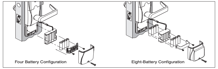
Batteries
To install or replace batteries
![]() Replacement of batteries does not affect any programmed data.
Replacement of batteries does not affect any programmed data.
![]() Battery voltage can be checked with the SUS.
Battery voltage can be checked with the SUS.
- Remove the battery cover.
- Remove the battery bracket. Do not allow the battery pack to hang from the wires.
- Install the new batteries (install only new AA Alkaline batteries).
- Reinstall the battery pack and battery bracket.
- Reinstall the battery cover. Be careful not to pinch the battery wires when installing the battery cover.
CAUTION! Danger of explosion if battery is incorrectly replaced! Replace only with the same or equivalent type. Dispose of used batteries according to the manufacturer’s instructions.
This product has been evaluated for ULC-S319 compliance with AA and coin cell batteries listed below. For installations requiring ULC-S319, these battery models should be used.
AA batteries: Duracell PC1500, MN1500; Energizer E91, EN91, AX91, XR91; RayoVac 815, 815-HE
Coin cell batteries: Energizer CR2025, CR2032; Maxell CR2025, CR2032, Panasonic CR2025, CR2032; RayoVac KECR2025, KECR2032.
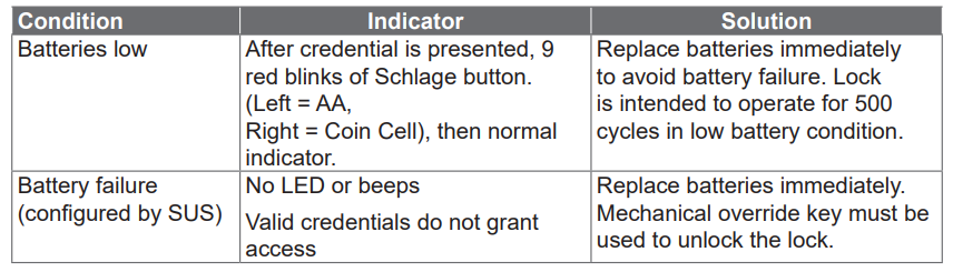
Low battery indications
![]() During low battery condition, the reader’s beeper will be temporarily disabled. This condition will revert to normal function when batteries (AA or coin cell) are replaced. (While the beeper is in temporary disabled state, the SUS will indicate beeper is “on” as previously set by the user.)
During low battery condition, the reader’s beeper will be temporarily disabled. This condition will revert to normal function when batteries (AA or coin cell) are replaced. (While the beeper is in temporary disabled state, the SUS will indicate beeper is “on” as previously set by the user.)
Battery failure modes
![]() The battery failure mode is set using the SUS. See the SUS User Guide for more information.
The battery failure mode is set using the SUS. See the SUS User Guide for more information.
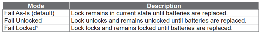
1 Fail Unlocked and Fail Locked modes are not available if the lock is externally powered.
External power supply
 The AD-200/AD-201 may be connected to external power using a UL294 listed power supply for UL installations, and a power supply that complies with CAN/UL-S318 or CAN/ULC-S319 for cUL installations. The power supply must be capable of sourcing at least 250mA @ 12 or 24 VDC (Schlage PS902, PS904, PS906).
![]() When powered with external power supply, the lock will always fail “As‑Is” if power is lost.
When powered with external power supply, the lock will always fail “As‑Is” if power is lost.
LED Reference
Most LED and beep indicators are configured using the SUS. See the SUS user guide for more information.
Schlage button
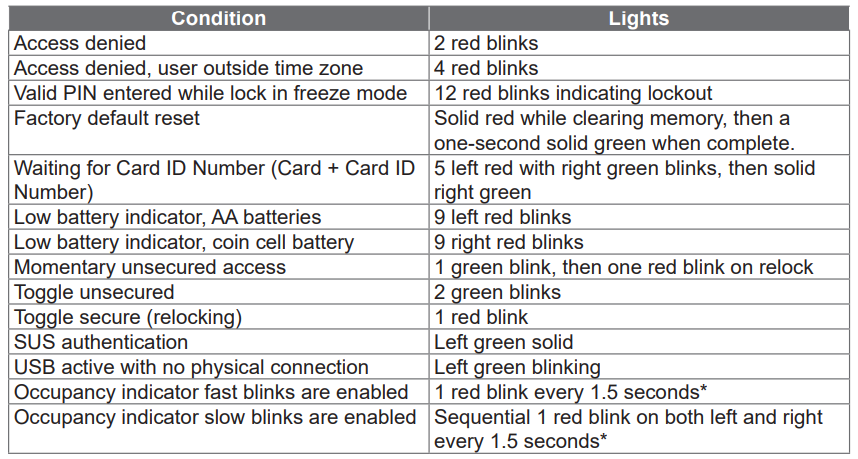
* The red blinks will turn amber if the lock’s battery is low.
Optional Inside Push Button (IPB)
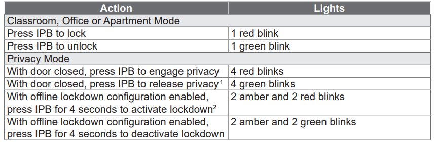
1 If DPS is used, then opening the door will also release privacy. If mortise deadbolt is used, then retracting the deadbolt will also release privacy.
2 Opening of door or deadbolt retraction will not deactivate the offline lockdown mode when it is active.
Optional Inside Push Button (IPB)
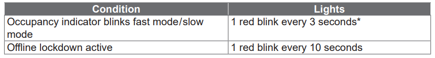
* The red blinks will turn amber for the occupancy indicator blinks when the lock’s battery is low.
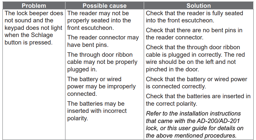
Troubleshooting

FCC/IC Statements
Allegion Agency statements
Compliance Statement
This device complies with Part 15 of the FCC Rules.
Operation is subject to the following two conditions:
- This device may not cause harmful interference, and
- This device must accept any interference received, including interference that may cause undesired operation.
Warning
Changes or modifications not expressly approved by the party responsible for compliance could void the user’s authority to operate the equipment.
FCC interference statement
This equipment has been tested and found to comply with the limits for a Class B digital device, pursuant to Part 15 of the FCC Rules. These limits are designed to provide reasonable protection against harmful interference in a residential installation. This equipment generates uses and can radiate radio frequency energy and, if not installed and used in accordance with the instructions, may cause harmful interference to radio communications. However, there is no guarantee that interference will not occur in a particular installation. If this equipment does cause harmful interference to radio or television reception, which can be determined by turning the equipment off and on, the user is encouraged to try to correct the interference by one of the following measures:
- Reorient or relocate the receiving antenna.
- Increase the separation between the equipment and receiver.
- Connect the equipment into an outlet on a circuit different from that to which the receiver is connected.
Consult the dealer or an experienced radio/TV technician for help.
Industry Canada statements
This equipment has been tested and found to comply to Industry Canada ICES-003.
CAN ICES-3(B)/NMB-3(B)
Customer Service1-877-671-7011 www.allegion.com/us
© Allegion 2020P516-129 Rev. 04/20-p
References
[xyz-ips snippet=”download-snippet”]