

Installation manual
System “bp308”
- General instructions
- Safety instructions
- Commissioning
- EU Type Examination
General information
Thank you for the confidence you have placed in us by purchasing “bp308” of Böhnke + Partner GmbH. Please take the time to read this installation manual and documentation on components carefully. Improper handling results in a high risk of injury. Follow all the instructions and you will save a lot of time and questions during installing the system.
“Installation manual” stands for the whole documentation that we have prepared to provide our customers with comprehensive information on our company and product range. To obtain a better overview, the manual has been divided into several parts. The “Installation manual” tells you about the hazards and risks, which can result in serious health problems and economic damage in case of incorrect behaviour. Furthermore, it will provide you with the necessary information on commissioning of the control system. The installation manual is supplied with every control system and is thus part of the complete control system documentation.
Intended use
The control system is an equipment for using in lifts.
Documentation references
This manual does not provide information on our overall delivery options. All information only serves to describe the product and must not be regarded as granted characteristics in the legal sense. Any claims for damages against us, irrespective of the legal basis, are excluded unless we are guilty of deliberate intent or gross negligence. We do not assume any guarantee that the specified circuits or procedures are free of copyrights of third parties.
Reproduction, even in extracts, is permissible only with the consent of Böhnke + Partner GmbH and with precise reference to the source. Böhnke + Partner logo and company name are protected trademarks.
The information in this manual is regularly checked. The necessary corrections are included in subsequent editions.
Hazard warnings and special information are given in this technical manual in the following way and highlighted with a corresponding symbol.
Safety instructions
Qualified personnel within the meaning of the documentation or warnings on the product are persons, who are familiar with setup, assembly, commissioning, operation and maintenance of the product and have the relevant qualifications for the activity, e.g.:
- Training and briefing or authorisation to switch on and off, earth and label the current circuits and devices according to the standards of the safety technology.
- Training and briefing in maintenance and use of appropriate safety equipment according to the standards of the safety technology.
- First-aid training.
Safety instructions for control system
- Assistance by another person: If a fitter is performing an activity, which requires the presence of another person, this person must be an expert or trained in hazards.
- Implementation of work
- Entering and leaving the car roof: The car roof may be entered only in the presence of experts. Before entering the car roof, the emergency brake switch (“emergency stop”) and, if accessible, the inspection switch on the car roof must be switched on and their functioning checked. The shaft doors may be closed only after the inspection control system is switched on. The functioning of the emergency brake switch and the inspection switch is checked, e.g. by closing the doors and enabling the landing call. The lift must not move in the process. Before leaving the car roof, the effectiveness of the shaft door contact with the exit doors must be checked, the emergency brake switch enabled and after opening the shaft door the inspection switch must be unlocked again. The emergency brake switch may be unlocked again only after leaving the car roof.
- Shaft lighting: Before beginning work in the shaft, sufficient lighting must be ensured, e.g. switch on the shaft lights and carry along a network-independent light.
- Stay and travels in the shaft: There should not be more people on the car roof and more material must not be taken along than is necessary for carrying out the work. Load-bearing capacity and usable area must be kept in mind. Driving on the car roof is permissible only when there is no one present in the hazard zone. It is forbidden to carry out work during the travel. Inspections (visual inspections) are only permissible during downward travels. There is a danger of crushing during upward travels, e.g. at counterweights and shaft fittings
- Electrical hazard: After the main switch is switched off, voltage may remain in various equipment and components of the lift.
- Bridging of safety equipment and control lines: It is strictly forbidden to bridge safety equipment, control lines and the switches. If it is not possible to avoid bridging in order to carry out work, it may be done only if:
- the person carrying out the work is trained in it
- the bridges are suitable and clearly recognizable for everyone.
The bridges must be removed immediately after the work is completed.
Installer and operator requirements
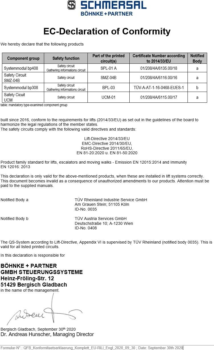
EU Type Examination
The system module bp308 contains an electronic monitoring unit for the safety circuit and a pre-control for the contactors. Moreover, a safety circuit (SMZ) is located on the circuit board. The safety circuit can be used in the following cases of EN 81-20/-50 and EN 81-1/-2:
- Preparatory measures with lift car and shaft door open
- Levelling with lift car and shaft door open
- Re-levelling with lift car and shaft door open
- Detection of an unintended movement of the lift car with open doors (UCM).
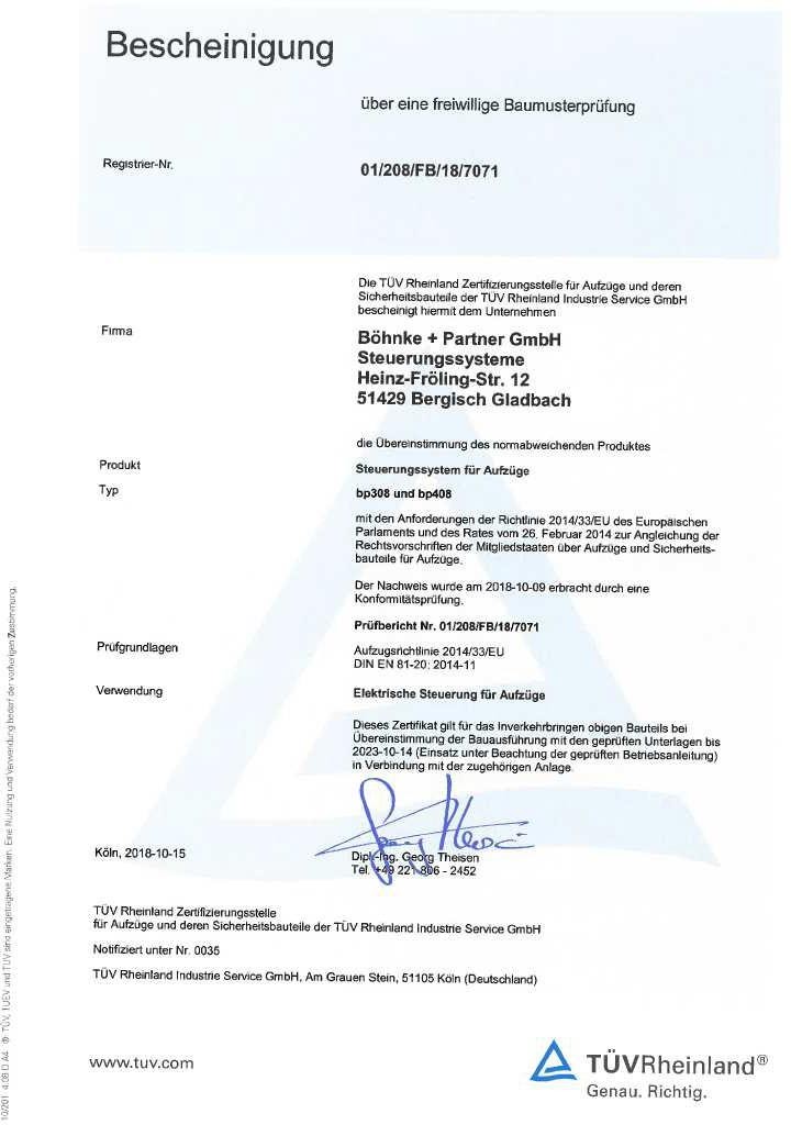
EU Type-examination certificate BPL-03 with SMZ
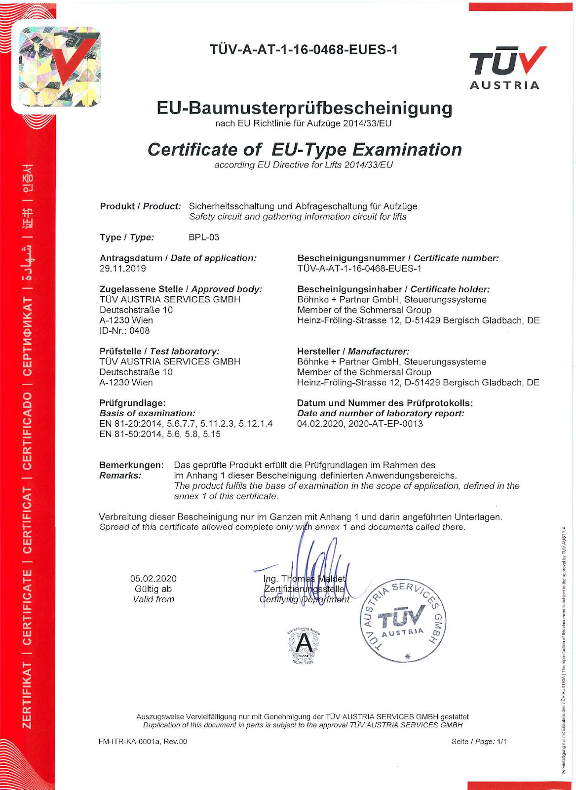
System module bp308 – Safety circuit and gathering information circuit for lifts BPL-03 Reg. no. TÜV-A-AT-1-16-0468-EUES-1 dated 2020-02-05
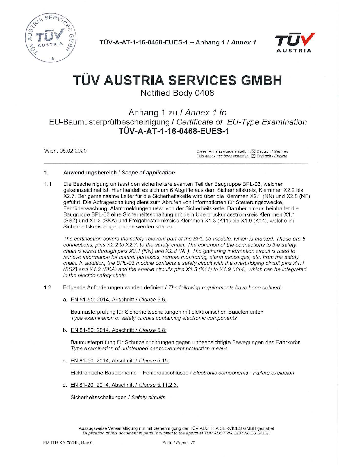
Type Examination BPL-03 – Annex 1 Page 1/7
Reg. no. TÜV-A-AT-1-16-0468-EUES-1 dated 2020-02-05


Voluntary type examinations
Compliance of product deviating from the norm with requirements of the directive 2014/33/EU
Voluntary type examination – Compliance of product deviating from the norm with requirements of the directive 2014/33/EU – Page 1 of 3
Voluntary type examination – Compliance of product deviating from the norm with requirements of the directive 2014/33/EU – Page 2 of 3

Voluntary type examination – Compliance of product deviating from the norm with requirements of the directive 2014/33/EU – Page 3 of 3
Return from inspection operation after use of the pit inspection control by operating controls
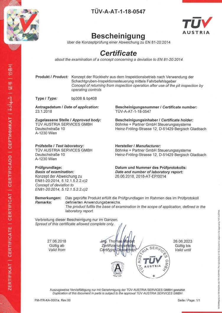
Certificate about the examination of a concept concerning a deviation from EN 81-20:2014 : Return from inspection operation after use of the pit inspection control by operating controls
Test report on certificate about the examination of a concept concerning a deviation from EN 81-20:2014 : Return from inspection operation after use of the pit inspection control by operating controls – Page 1 of 4
Test report on certificate about the examination of a concept concerning a deviation from EN 81-20:2014: Return from inspection operation after use of the pit inspection control by operating controls – Page 2 of 4

Test report on certificate about the examination of a concept concerning a deviation from EN 81-20:2014 : Return from inspection operation after use of the pit inspection control by operating controls – Page 3 of 4

Test report on certificate about the examination of a concept concerning a deviation from EN 81-20:2014 : Return from inspection operation after use of the pit inspection control by operating controls – Page 4 of 4
EMC Directive
All industrial, electronically controlled automatic control elements (PCs, microprocessors, computers, PLC) can be influenced by interference impulses if counteractive measures are not taken. These interference impulses can be generated by external systems such as voltage changes in supply line as well as control pulses of power elements of frequency inverters. Böhnke + Partner GmbH takes into account all the usual measures when manufacturing the control system. The components used have low sensitivity to interference impulses of the surroundings
Product and functional description
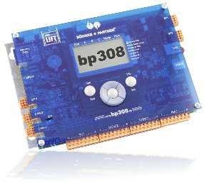
The control system bp308 is an electronic assembly for controlling lifts. Various designs with integrated safety circuit are available for selection, with safety circuit monitoring for various voltages.
Basic functions of a lift control system such as safety circuit monitoring and safety circuit have been consequently integrated in the control system bp308.
Control system bp308 is a decentralized microprocessor system with distributed “intelligence” The decentralized components are connected by default via the two CAN open lift interfaces in accordance with the international standard CiA 417 (www.CANopen-Lift.org). Furthermore, other protocols that are widespread in the lift construction, can also be processed.
The control system bp308 is equipped with all the modern interfaces of lift technology
The control system bp308 contains the following components
- Stabilized, primarily clocked power unit with 2 voltages
- 5 VDC, 2 A (internal only)
- 24 VDC, 2,2 A (at the terminals)
- Power fail recognition 150 VAC
- Emergency light 12 V, 600 mA, total discharge protection at 10 V
- Pre-control
- Safety circuit monitoring unit
- Safety circuit (optional)
- Freely programmable inputs, outputs and repays
- Electronically monitored standard inputs and outputs
The following interfaces are also integrated:
- Interface for activating inverters with DCP3, DCP4+ and CANopen Lift (CiA 417)
- Interface for absolute encoders of various manufacturers and technologies
- Interface for remote diagnosis of data with WinMOS®300 via Bluetooth™ or WiFi, modem (USB) or Ethernet
- Interface for building automation via EIS protocol, LONworks- standard, Modbus, OPC or Profibus DP
- Interfaces for CANopen lift components
- LAN for remote diagnosis and monitoring
- USB laptop connection for connecting a laptop for diagnosis and software updates
- USB host for USB sticks, modems, Bluetooth™ or Wi-Fi adapter
- Memory card slot for software updates, log files, and parameter backups
Because of the focus on functioning and decentralized control concept, small control cabinets can be used. The standard control cabinet for the control system bp308 has the size 600 x 600 x 300 mm (W x H x D). Thus, bp308 is predestined for use in lifts, in which only little space is available.
In collaboration with the remote monitoring system of data WinMOS®300 (www.WinMOS.de), the availability of the lift can be significantly increased. Using this system, complete conversion into demand-oriented maintenance is also possible.
Summary of the functions of bp308
- Control of a single lift
- Group control of up to 8 lifts without separate group computer
- 128 stops adjustable
- SFS – automatic push button control
- SFR – automatic push button control with landing call memory (“taxi control”)
- 1KS – one button collective control
- 1KSab – one button down collective control
- 1KSauf – one button up collective control
- 2KS – two-button up and down collective control
- Operating data logs: Travels, operating hours, malfunctions, messages
- Rope traction lift: pole-changing, one speed, two speeds, frequency inverter
- Hydraulic operated lift: Star-delta and direct start, valve control, soft start, frequency inverter
- PTC thermistor monitoring integrated for drive motor
- Safety circuit monitoring unit integrated(standard 230 V AC, optional 48 V AC/DC or 110 V AC)
- Main contactor selection 230 V AC integrated
- Safety circuit (SMZ) integrated
- Internal primarily clocked, stabilised and short circuit resistant mains power pack with terminal connector to the control unit
- Inputs and outputs integrated for all standard applications
- Positive circuitry (24 V DC)
- Outputs protected against overload
- Diagnosis of inputs and outputs via LCD or laptop
- Diagnosis and configuration of CANopen lift components with CANwizard®
- Operator guidance using laptop with WinMOS®300 or with Lift2CLOUD®
- Operator guidance with 7 buttons and illuminated, graphic LCDisplay
- Parameter setting on site using LCD, with mobile phone via Bluetooth™ or WiFi or laptop
- Parameters stored in EEPROM in a fail-safe way (2 complete data records)
- Real-time clock integrated
- Setup menu and service menu separate
- Code lock separately adjustable
- Menu guidance in German, English, Dutch and Swedish
- Interfaces for DCP, LAN, USB and CANopen lift are integrated
- Optional remote diagnosis via modem (USB) or LAN
- Different codes possible for landing signals and direction indicator (Gray, binary, user-specific)
- Zero load, full load, excess load, actual load in kg
- Direction indicator, landing gong, selecting landing door side as well as direction of travel
- Parking landing, fire brigade landing, emergency landing, emergency backup landing, monitoring and waiting landing adjustable
- Parking program adjustable via LCD
- Door tables 1, 2 and 3 externally switchable
- Magnet switch selector with 4 and 6 switches
- Absolute encoder selector with AWG-05 or CANopen lift devices
- Next landing short landing distance up to 15 mm (only with absolute encoder)
- Selective landing calls for door sides A, B and C
- Priority landing calls with two stages (low and high position)
- Door selection for sides A, B and C (all door operators)
- Doors adjustable to different times and functions
- Doors starting to open during landing approach and re-levelling function
- Bolt on door sides A, B and C can be activated separately (lockage control)
- Service intervals adjustable according to travels, hours and date
- Malfunction stack memory up to 128 messages (type of malfunction, landing and time (date and hour) as well as signal map)
- Malfunction list (type, landing and frequency)
- Batch memory up to 128 entries for important messages
- On-site monitoring possible using laptop
- Remote malfunction diagnosis with WinMOS®300 via modem or LAN possible
- 2 relays, freely programmable with one normally closed contact
- 2 relays, freely programmable with one normally open contact
- 4 relays, freely programmable with a changeover contact
- Company logo (text) adjustable on LCD
- Landing names (text) adjustable
- Optional guest operation, zone control, ramp movement, chemical operation, earthquake mode, operator mode and other special functions are possible
- Automatic and manual emergency rescue
- RoHS compliant production (lead free)
Decentralised lift control system
The control system bp308 is a decentralised control system. This means the “intelligence” is distributed across the devices connected and no longer at just a centralised location. CANopen lift application profile CiA 417 (www.CANopen- Lift.org) forms the basis for the decentralised lift control system. Communication between individual components of the group of lifts takes place via this application profile that is standard worldwide. The connected components have a complete functional image and thus can independently make a multitude of decisions. Thus, open modular systems are possible, which can undertake very complex control tasks.
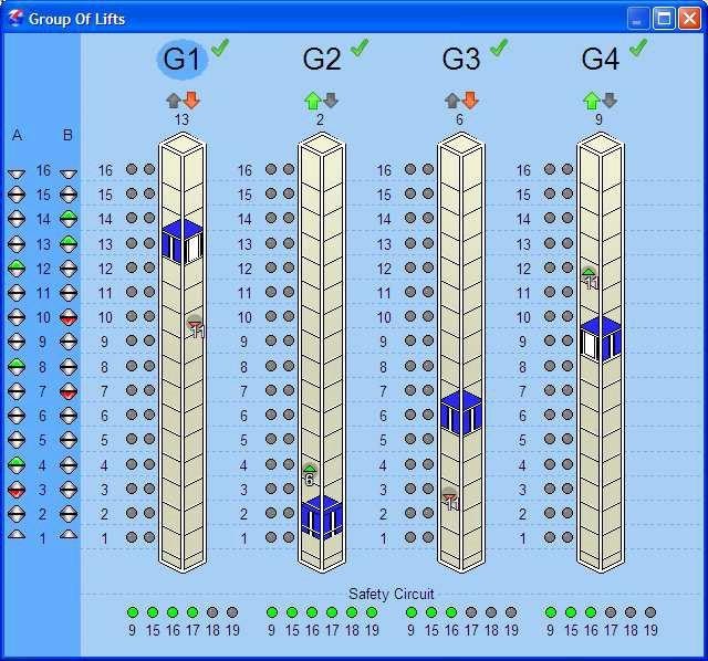
The group system
Modern group control systems are equipped with efficient 32-bit processors. They can assess a large amount of information of the entire group of lifts in a short time and based on that, take the correct decision for group mode.
The group control program ensures smooth lift operation in groups of two to eight lifts. The application profile CiA 417 based on CANopen lift forms its basis. Data and commands of all components are made available on the bus in a standard way. Every group computer is thus in the positionto independently decide the sequence in which individual calls must ideally be implemented and the group member that
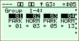
Figure 19:
Group status in bp308 implements them. A higher-level master computer is not necessary for the group function but can be used to increase the efficiency of the group by a few special functions, e.g. load-dependent evacuation of all lifts within a building with emergency power or in case of fire or automatic statistical evaluations for determining group parameters.
Landing calls are entered via bus nodes, which can be located in the landing call units or in the control cabinet. These nodes assess the incoming signal and sends the call with information about its direction, priority, destination etc. on the CAN bus to all group members at the same time.
In the group control system, the algorithms of the call controller decide with the help of the set parameters (e.g. park mode, number of parking lifts on the mail level, priority calls per landing etc.) the sequence in which and from which lift the individual destinations must be approached. If a lift is no longer part of group operation because it has been switched to inspection, for example, during maintenance, this information is also sent to the remaining group members immediately and can be taken into account in calculations. If several lifts can
implement a call at the same time, the lift accepts that call, which has runtime. If the runtimes are also the same, G1 applies before G2 …
The following states must be considered in the group algorithm along other things:
- Distance to target landing
- opposite travel /call direction
- Lift is stopped
- Number of intermediate stops on route
- Lift car call on the target landing
- and others.
Priority calls
When arranging priority calls to bp308 itself or a CANopen lift component such as CAP- 01/02 or CIO-01, which lifts can operate priority call is specified. The most effective of the selected lifts will operate this call. Two further options, “collect priority calls” and “several priority calls per landing” in the group setting of the service menu make it possible to call further lifts if one is already answering the priority call on the landing on which the standby delay. This option is intended for bed transports, for instance. A high priority landing call interrupts a low priority landing call. Otherwise, the same rules apply to high priority landing call as to the low priority landing call.
Presentation of group in WinMOS®300
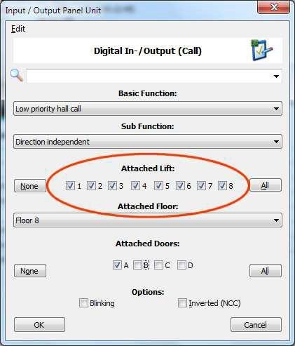
Specification of priority calls
WinMOS®300 offers the option of displaying a view based on group data in “Diagnosis” as well as “Monitoring”. In bp308, the call destination currently being operated by the lift is displayed in the group panel inside the lift shaft. Furthermore, ETA (Estimated time of arrival) of the call is also dynamically displayed in the panel. This can change the next moment – e.g. if the call situation changes. In this case, priority calls are displayed using a separate symbol, which also indicates whether the call has low or high priority.
This functionality enables a better comprehensibility of the processes in a group control system.
Display of dynamic call assignment of a group control system in WinMOS®300 in control system bp308
-
Components for bp308
For the control system bp308 Böhnke + Partner GmbH has currently provided the following components:
- Landing call unit CAP-02 (8 I/O)
- Car operation unit CLK-03
- CAN-Wireless-Interface CWI-01
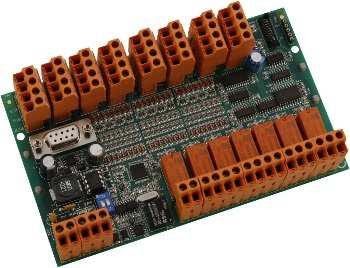
- CAN-I/O module CIO-01 (32 I/O)
- CAN serial interface CSI-01
Other components from various manufacturers such as absolute encoders or panels, which comply with the standard CiA 417, are available and can be used.
An overview of deliverable CANopen lift components and their description can be found on the Internet under www.CANopen-Lift.org.
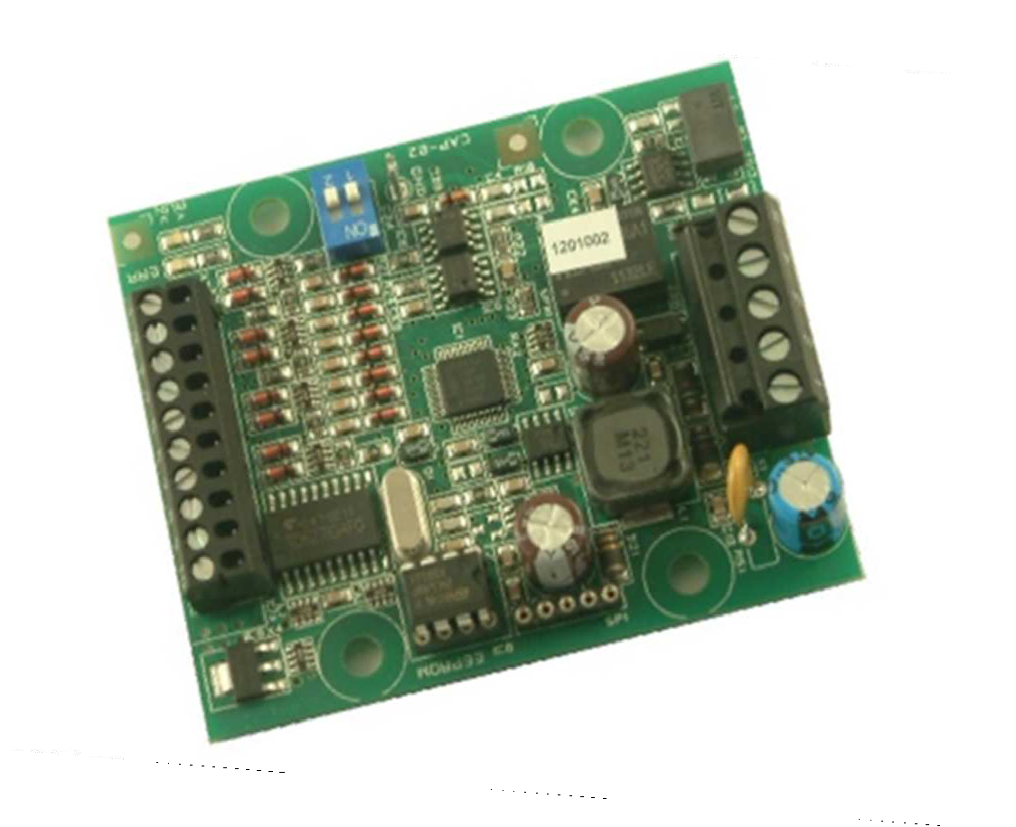
Board CAP-02 for connecting the landing calls to the CANopen lift bus
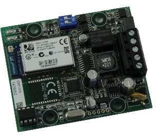
Board CWI-01 for remote control of the control system (e.g. from the car) using a mobile device (phone, tablet, notebook).
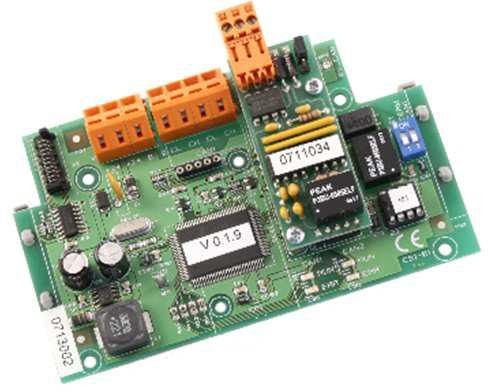
Board CSI-01 for using as repeater or bridge
Board CLK-03 for connecting the car electronics to the CANopen lift bus
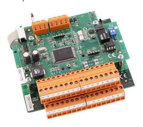
Board CIO-01 for connecting 32 inputs/outputs or calls
Versions of bp308
This installation manual refers to all versions of the control system bp308. The following abbreviations are used in the product names:
SMZ = Safety circuit
48 V = Option 48 V safety circuit monitoring 110 V = Option 110 V safety circuit monitoring
The bp308 is available with 48 V AC/DC, 110 V AC and 230 V AC safety circuit input voltage and each with and without safety circuit. .
Overview
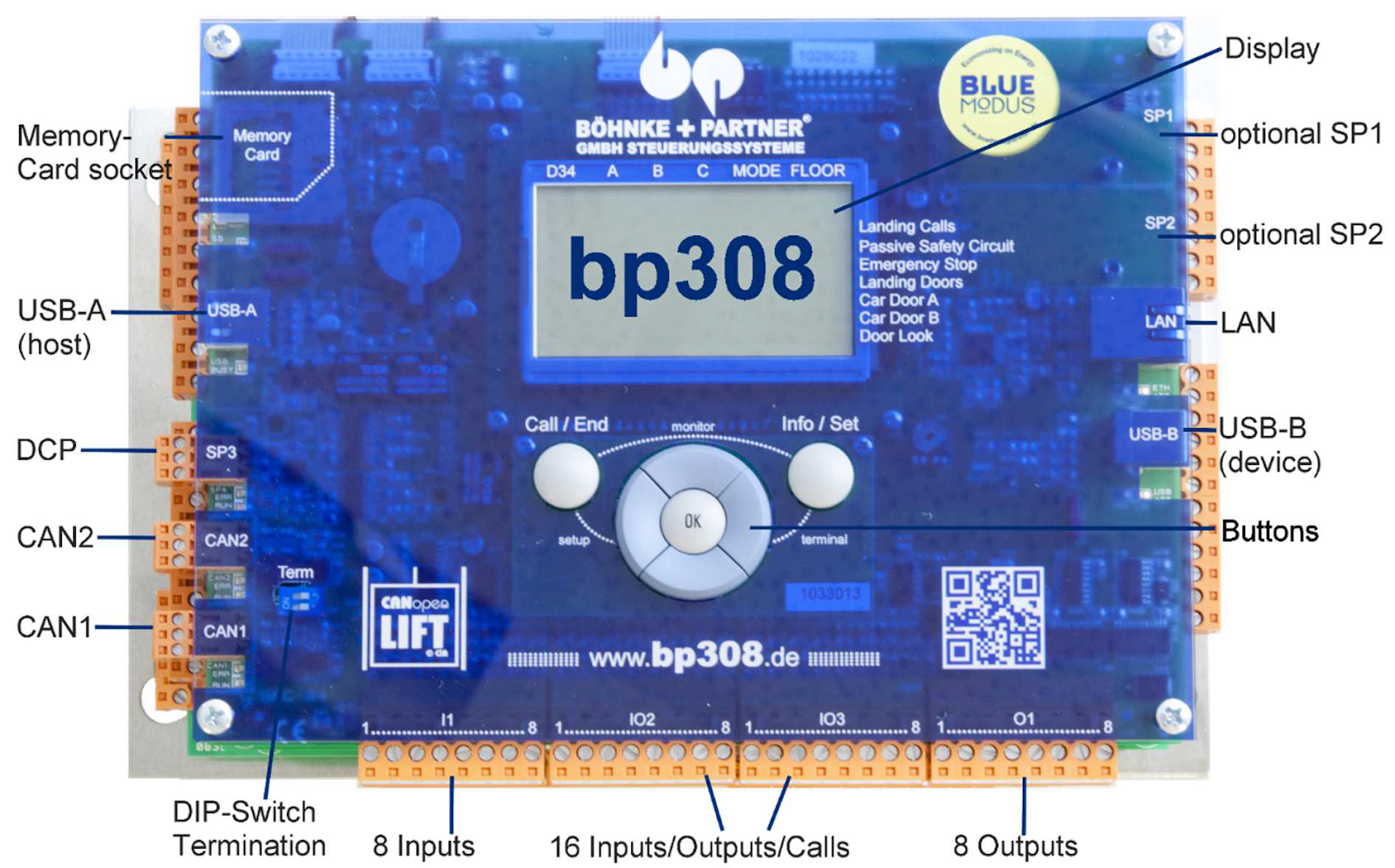
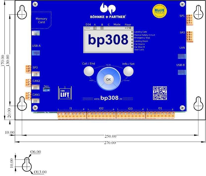
Top view
Left side view
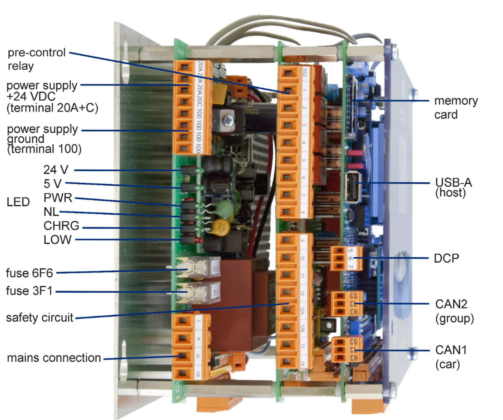
Bottom view
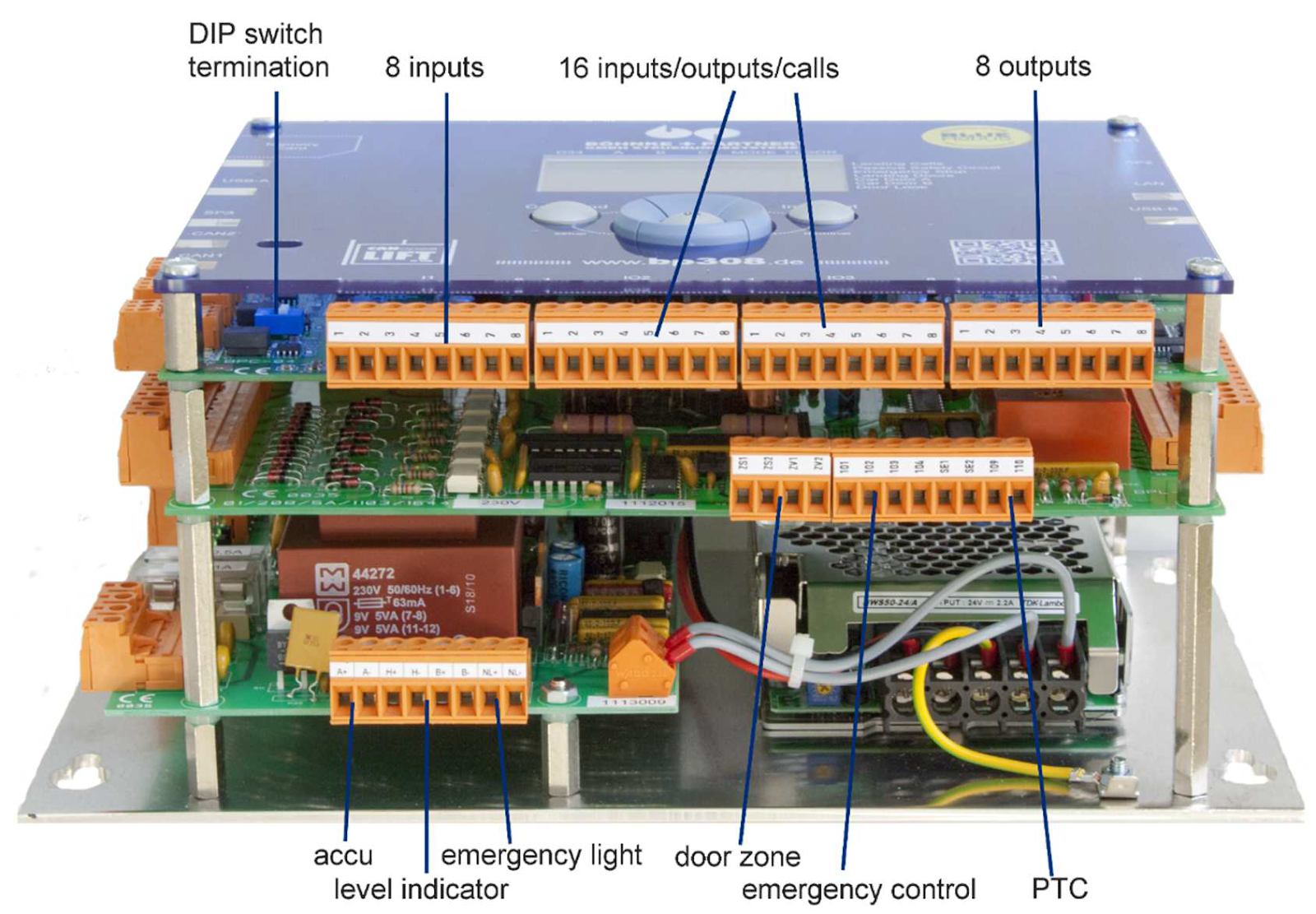
Right side view
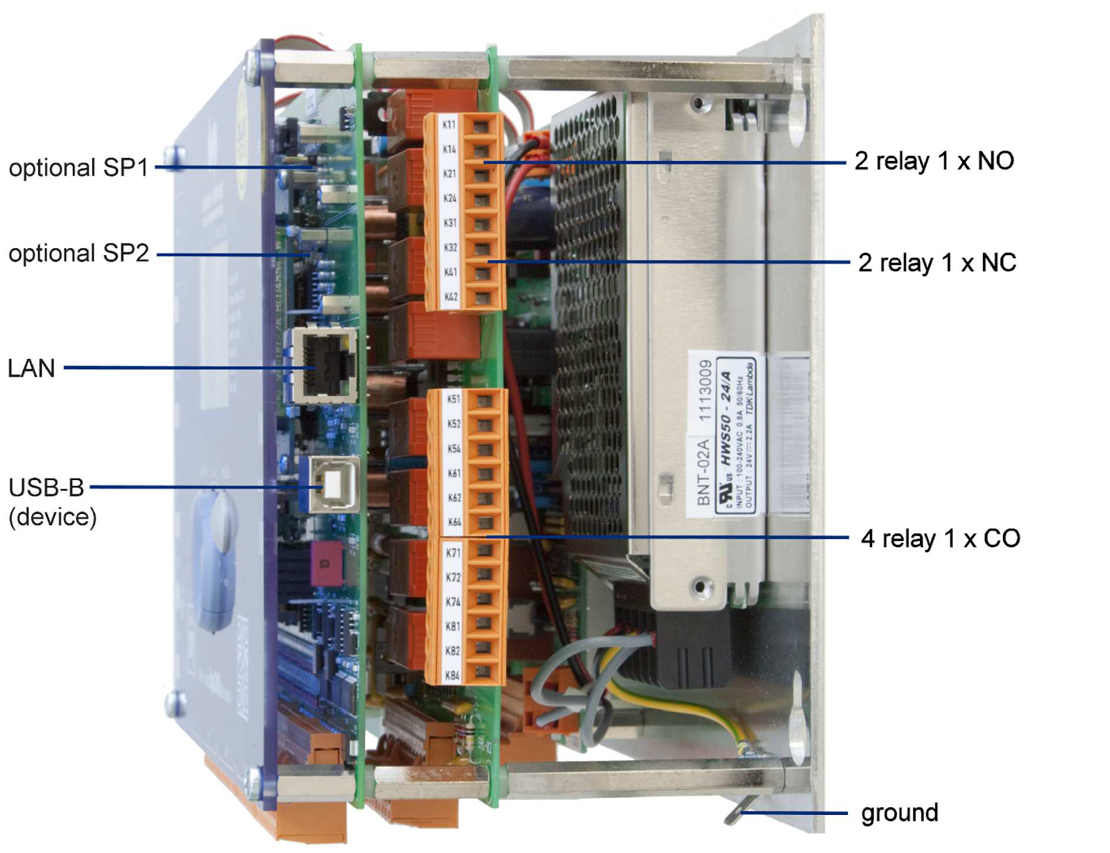
Technical features
|
bp308 |
||
|
Technical features |
||
|
Regulations |
EN 81-1 / -2; EN 81-20 / -50 |
|
|
Mechanical data |
||
|
Dimensions (H x W x D) |
170 x 270 x 180 mm |
|
|
Connection version |
Screw and plug terminals |
|
|
Installation position |
To be installed lying on vertically installed assembly plate in the control cabinet |
|
|
Control cabinet assembly |
At least IP2xD |
|
|
Guidelines |
Lift Directive (2014/33/EU), RoHS (2011/65/EU), EMV (2014/30/EU) |
|
|
Electrical data |
||
|
Supply voltage |
24 V DC +/-20% |
|
|
Ports |
(2 normally closed, 2 normally open, 4 changeover contacts) |
|
|
Interfaces |
– RS-485 (DCP)
|
|
|
Indicators and control element |
Graphic display with navigation keys:
|
|
|
Performance data |
||
|
Application range |
Passenger and freight lifts |
|
|
Stops |
up to 127 |
|
|
Operating mode |
|
|
|
Copying tool |
digital with absolute encoder system |
|
|
Software |
||
|
Memory |
Malfunction, maintenance and message stack with max. 128 entries |
|
|
Language settings |
German, English, French, Italian, Swedish, Dutch |
|
|
Groups |
integrated group algorithms for up to 8 lifts |
|
|
Functions |
For comprehensive standard and special functions, see chapter 5.2 |
|
|
Remote-controlled control menu |
Via WLAN/Ethernet with mobile device or PC with WinMOS®300 as APP or PC software |
|
|
Backup/update |
Backup and update via SD-card or USB stick |
Control panel and LCD in bp308
With the help of the graphic LC display and the control panel, the state of the lift can be determined and parameters in the control system and connected CANopen lift devices changed.
Standard view
After the system is switched on and during normal mode, if special menu is not called, the standard view is displayed on the display. This view gives a quick overview of the latest state of the lift and provides individually configurable information.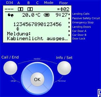
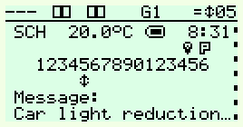
The following information is displayed on the LCD by default:
- Lift status bar
- Safety circuit status bar
- Logo “SCH” (or customer-specific characters)
- Optionally also the board or cabinet temperature,
- State of internal buffer battery
- Current system time
- And depending on the configuration:
- current malfunctions or messages
- last malfunction
- statistical information
- current speed of lift
Lift status bar
The lift status bar is located in the top part of the display. It is displayed in all menus. The following information is displayed in the lift status bar:
- Pre-control (relay K1-K3)
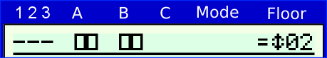
- Doors A/B/C with limit switches and reversal signals (photo-cell, door open push button)Mode (e.g. inspection mode)
The lift status bar is displayed in all menus
- Position information (flush level control) +/ =/ –
- Direction indicator of travels
- Car position
Safety circuit status bar
The safety circuit status bar is located on the right side of the display. It is displayed in all menus. In the safety circuit status bar, the status of the safety circuit of terminals is displayed: The safety circuit status bar is displayed in all menus
Control panel
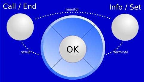
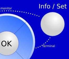
The control panel is located below the display. The control panel comprises 7 keys, using which you can navigate through the different menus, status information is displayed and parameters can be changed. The keys of the control panel must be arranged as central navigation block with keys “Up”, “Down”, “Left”, “Right” and “OK”. The “Call/End” key is located to its left and “Info/Set” key to its right.
|
1 |
→ |
passive safety circuit |
(terminal 10) |
|
2 |
→ |
Emergency stop |
(terminal 11) |
|
3 |
→ |
Shaft door |
(terminal 12) |
|
4 |
→ |
Car door A |
(terminal 12A) |
|
5 |
→ |
Car door B |
(terminal 12B) |
|
6 |
→ |
Bolt |
(terminal 13) |
Figure 30:
You can navigate through the menus using keys of the control field.
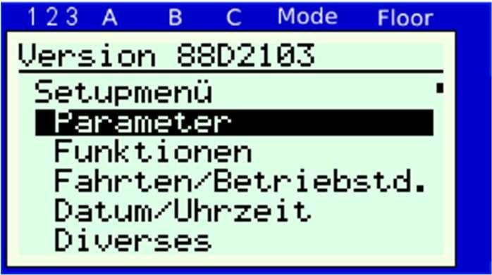
The setup menu contains basic parameters, which cannot be changed during ongoing operation of the lift, e.g. cable or hydraulic lift, number of stops, or the like
To go to the setup menu, proceed as follows:
- Ensure that nobody is present in or on the lift and the system can be safely switched off.
- Now hold down the left key “Call/End” and briefly tap the key “Left”.
The following screen appears: > Start in setup menu…
Now you are in the setup menu. All control functions are now switched off. If a setup code (secret code) is agreed, please enter the correct code. The default setting of Böhnke + Partner GmbH is >5061<.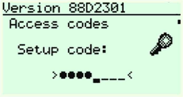
After entering the correct code, you can call and change the menus and parameters.
Input of setup code
You can exit the setup menu by briefly pressing the key “Call/End”. A restart is executed and then the start panel of bp308 is displayed again.
In the service menu of bp308, parameters and time, which are not safety-relevant and which can be changed during ongoing operation, can be adjusted, e.g. door time, energy-saving functions BlueModus on/off etc.
Press the “OK” key, the display automatically jumps to the service menu. If a service code (secret code) is agreed, the correct code must be entered. A service code is not set by default by Böhnke + Partner GmbH.
After entering the correct code, you can call and all menus and parameters of the service menu and change during on-going operation. If the control system is to be encrypted again after exiting the service menu, press the “Left” key until the following question appears in the LCD: “Activate service code?”
Confirm with “OK” key. The following note will appear shortly:
The service menu of bp308
Code activation
Service code activated
You will then return to the start menu of bp308.
The service code can be changed or reset in the service menu under MISCELLANEOUS > ACCESS CODES > SERVICE CODE
From service menu, you can directly go to the call menu by clicking on the “Call/End” key. If the call menu is active, it is displayed in the lift status bar using a diamond symbol.
In the call menu, a car call can be made by clicking on the topmost or bottommost stop. By clicking on the “OK” key, you can change the destinations of upper/lower car call to Next upper or lower car call. Now you can
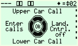
The call menu of bp308 is signalled using a diamond in the lift status bar enter a direct car call in the next stop from the current position in upward or downward direction. You can also select between open/close door by further clicking in the call menu.
If you want to enter car or landing calls on special landings, you can call the Calls dialogue by clicking on the “Left” key. Here you can select the desired call type and then enter the landing- and door-related calls.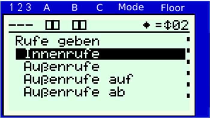
If you are in the call menu, you can activate or deactivate the landing control by clicking on the “Right” key. If the landing control is deactivated, it is displayed in the message window.
The information menu enables you to toggle between two menu options with a click. Thus, you can change parameters at a point in the service menu and with a click view the response in the system, e.g. travel signals.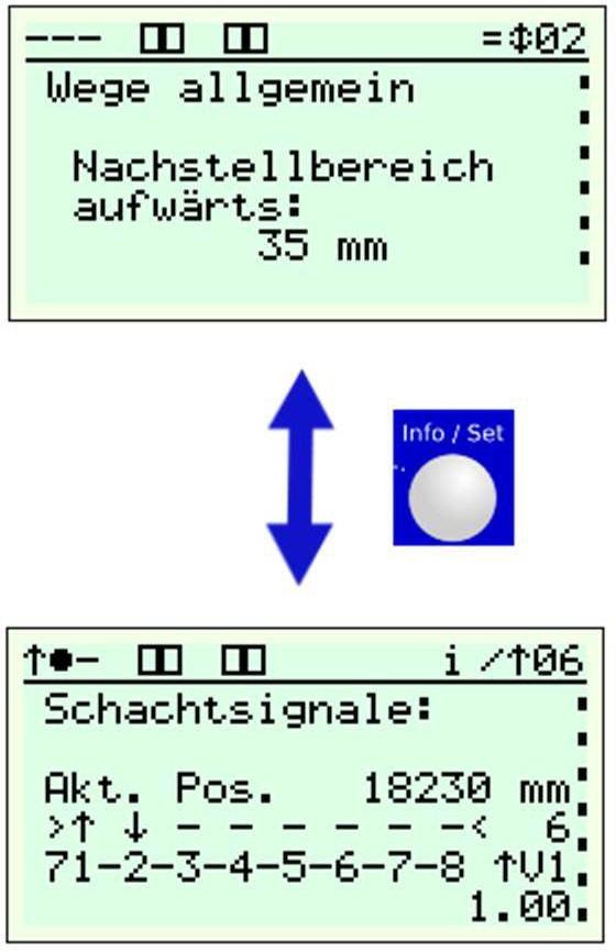
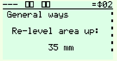
In order to toggle in the information menu, click on the Info/Set key once. If the information menu is active, it is signalled with an “i” in the lift status bar. Now you can navigate through the menu. With another click, you are again at the menu point, where you had activated the information menu. You can now toggle between the two menus with a single click.
Terminal mode
The following procedure has been specified in the application profile CANopen Lift (CiA 417): An assembly that is connected to the CAN-Bus sends the content of the display to another device via bus. It represents the content.
In this way, it is possible to navigate through the menu of the external device.
This procedure was integrated in the control system bp308 and is available in the menu under node list and in the terminal mode specially for the frequency inverter.
It is possible to toggle to the terminal mode by simultaneously pressing the keys Info/Set and “Right” and the menu of the frequency inverter connected is displayed on the display of bp308. The signals of the navigation keys “Up”, “Down”, “Left”, “Right”, “OK” and “INFO/SET” are now sent to the frequency inverter. By
pressing the “Call/End” key for minimum 3 seconds, the terminal mode is ended and the last menu point of bp308 can be seen again.
You can switch over to the terminal mode by simultaneously pressing the keys Info/Set and Right.
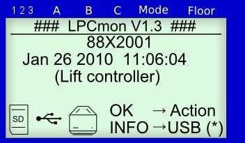
Monitor program LPCmon
Using the monitor program “LPCmon”, the program version of the lift software is monitored and the software of the system is updated. This process should be carried out by trained personnel only when requested by Böhnke + Partner GmbH.
Start of the monitor program
To go to the monitor program of bp308, first ensure that nobody is present in the lift and deactivating the lift will not result in a hazardous situation.
Hold down the “Call/End” and “Info/Set” keys simultaneously for at least 3 seconds. The monitor is thus started. All control functions are now switched off.
General information
Items of the interfaces and EEPROM are given in the figure. The digital control electronics with the processor, program memory as flash, parameter memory as EEPROM, real-time clock, battery, LC-Display and keys are located on the circuit board. The interfaces for two CAN networks, serial remote data transmission, USB or Ethernet, USB host and USB device and serial activation of a inverter via DCP are also accommodated on this board. In addition, bp308 has 8 inputs, 8 outputs and 16 calls, which can also be parameterised as inputs or outputs. The lift program is located in the Flash memory. All lift-related parameters such as lift type, stops, doors, time, parking landing etc. are stored in EEPROM in a fail-safe way.
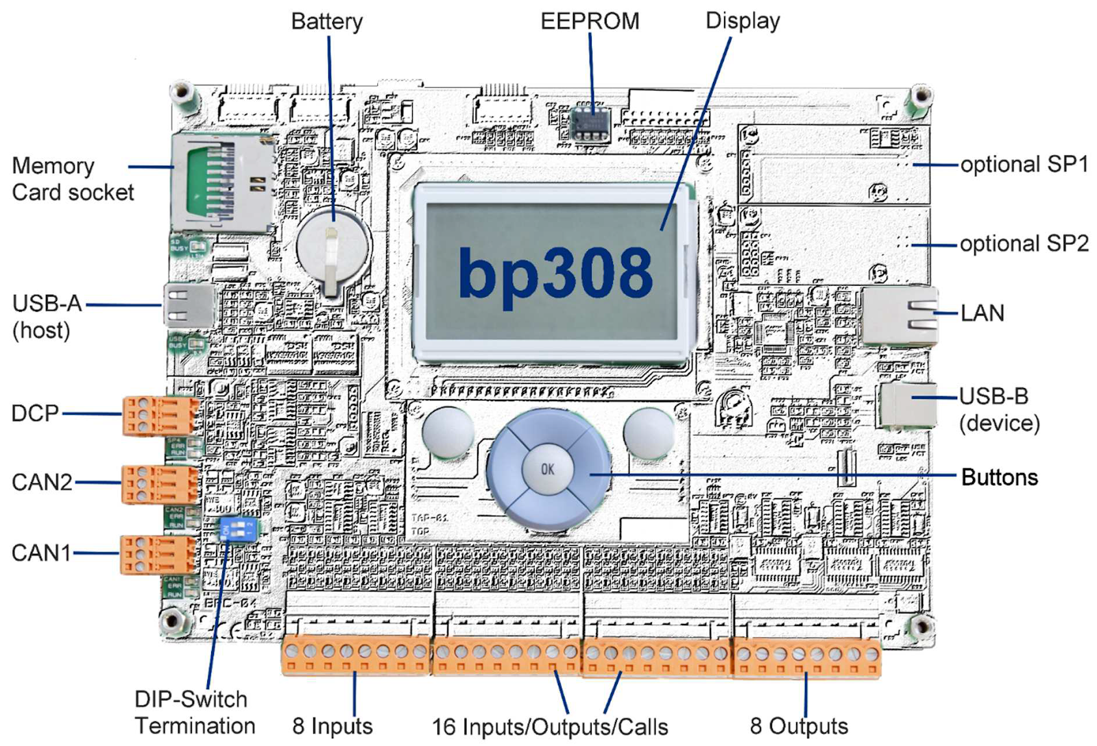
Figure 40:
Overview bp308 and the arrangement of its key components and interfaces.
Battery
A replaceable battery, which is necessary for buffering date and time, is located below the control panel on the upper board of bp308.
The replacement of the battery is only permitted in the disconnected state of the controller. The battery can be carefully removed from the holder. In order to insert, the new battery is pushed below the holder. While doing so, attention must be paid to polarity. Battery replacement is now completed.
The battery is a type CR 2032 and shall only be replaced with the identical type.
Replacement
When replacing the EEPROM using an EEPROM puller, pull the existing EEPROM straight out of the socket. The new EEPROM is slightly pressed into the socket horizontally. While doing so, attention must be paid to the marking (slot) in order to insert the component correctly.
Software update
A software update is always necessary when the system is to be subsequently equipped with additional functions. It is necessary to replace the EEPROM only when the board must also be replaced and the lift-specific data is to be transferred to the new board.
There are several options for carrying out a software update. It can either be done using SD-card or a USB stick or via the USB-B interface using a laptop.
To carry out an update via SD-card or a USB stick, insert the memory card with the new software version into the memory card holder or the USB stick into the USB-A port of the bp308. After switching on the control system, hold down the keys “Call/End” and “Info/Set” for at least 3 seconds in order to start the monitor program LPCmon. After clicking on “OK”, it is possible to select the storage medium (USB stick) that contains the new program version using the menu point Open file . Then navigate to the file on the medium (e.g. 78D2508.BIN) that contains the new program and select it. The software can now be updated. Follow the instructions on the display.
The system must be restarted after a successful update. For this, press the “Call/End” key. The system start and the following system check should now run faultlessly. The version number of the latest program version can be seen under system information in the service menu on the display.
The name of the program version is based on the following key:
- 78 = for target hardware:
- 78 – bp308
- D = main version identification:
- D – Standard main version (no longer modified)
- S – special version (customer version deviating from standard)
- X – current interim version (later becomes D-Version)
- 21 = annual key of programming:
- 21 – 2011
- 22 – 2012 etc.
- 01 = current version number
Using the software “Fw308”, a software update can also be carried out using a laptop via the USB-B interface. For assistance when handling this program, please contact a service employee of Böhnke + Partner GmbH.
Control system bp308 in the control cabinet with inverter
The control cabinet is supplied as a painted steel sheet housing. The wall cabinets have mounting holes or threaded bolts on the backside, to which the supplied mounting attachments can be screwed.
Floor-standing cabinets are mounted on supplied pedestals or on a prepared frame.
Assembly is done vertically. Existing inlets and outlets for air conditioning must be kept free. Please ensure there is sufficient sound insulation to the building in case of critical environments. In this case, all contactors and the entire assembly plate can be supplied as pre-mounted in the cabinet with sound insulation.
A sound pressure level of approximately 55 db(A) has been measured at 1 m distance and 1.6 height at our standard control cabinets, with closed control cabinet doors and a control system bp308. This is equivalent to a volume between a quiet radio [40 db(A)] and a normal conversation [60 db(A)].
The cable inlets are located at the bottom of the control cabinet. Use the corresponding inlets and attachments for properly attaching the incoming lines and cables.
Control cabinet:
- closed (DIN 41488)
- Textured coating RAL 7035 (light-grey)
- Mounting plate with cable channel
- Main contactors on rubber-bonded metal (only upon request)
- Protection class up to IP 54 possible
- Filter protector on request
- Door lock: Triangular sash lock or special closure
- Wall fastening
- Cable inlet below
- Dimensions W x H x D:
800 x 800 x 300 mm standard
1000 x 1200 x 300 mm regulated (frequency inverter installed)
Safety circuit
- 48 V AC/DC, 110 V AC or 230 V AC
Rectifier
- Brake (cable) 180 V DC / 4 A
- Bolt (optional) 180 V DC / 4 A
- Valves (hydraulic system) 180 V DC / 4 A
Travel contactors
- Rated current 14 A
- Power 7.5 kW AC 3-operation
- Make Schneider
(other makes optional)
Terminals
- Make Weidmüller or WAGO PTC resistor request
|
||
|
Normal mode |
< 2.2 kΩ; |
|
PTC resistor trip |
> 2.7 kΩ |
Control system
- System module bp308, 32-Bit processor system Safety circuit (integrated)
- for re-levelling, doors opening early and deletion of an accidental car movement with open doors
Shaft copying
- Magnetic switch,
- Absolute encoder (AWG),
- other encoder systems on request Inspection box
- Metal housing
- Control elements integrated in the inspection box Documentation
- Circuit diagram (DIN A4 copyable)
- Equipment marking in clear text in circuit diagrams
- Parts list of control system and terminal assignment plan
- Description of central unit with programming overview
- Description of general operating instructions
- TÜV operation templates of bp308 with valid connection assignment and description of the safety circuit
Regulations:
EN 81, SIA, ÖNORM, DIN, VDE, VBG 4
Easy servicing thanks to clear structure
The cable channel is wired on the base plate according to industrial standard. A cable wiring channel serves as manoeuvring room for incoming lines. All terminals of the processor are led to a separate terminal block at the bottom of the control cabinet. The control system is installed on a galvanised assembly plate. The sizes and dimensions stated here are applicable to a standard design of lifts with eight or more landing call points and with main drive power up to maximum 15 kW. We supply higher power on request.
Optional equipment
Uninterruptible Power Supply (UPS)
Böhnke + Partner GmbH supplies control systems for the lift industry. Optionally, the control system ordered by you can be equipped with a UPS, which should contribute to function preservation of emergency operation in case of power failure.
The compact and powerful UPS used by us is part of the newest generation of UPS devices. High reliability, low operating costs and excellent electrical properties are important advantages of the technology used.
The efficiency of the UPS system is designed on site for the use that you specify. As the UPS system must be operational in an emergency, the operational readiness must be checked regularly.
The operator is responsible for constant operational readiness of the UPS. He can transfer this task to the company entrusted with the maintenance work of the lift.
Operational readiness of the UPS system
Böhnke + Partner GmbH supplies control systems with integrated UPSs and expects operational installation of components within four months.
If the UPS system is not immediately installed, it must be stored in a place, in which the temperature lies between +5° and +40°C and the relative humidity is always below 90%. If the transport container has been removed, the UPS must also be protected from dust. The UPS system contains tightly sealed, maintenance-free lead batteries, which however can suffer damage if they are stored for a long time in discharged state or are exposed to high temperature. Therefore, the storage time must not exceed: six months at +20°C, three months at +30°C and two months at +35°C, without recharging the batteries. Ensure that not more than six months pass between two battery charges.
Installation and assembly
Before installing and commissioning the control system, please read the safety instructions and warnings carefully and follow all the warning signs attached to the device. Make sure the warning signs are legible and replace missing or damaged signs.
Storage, transport and operating conditions
.
Preparations
The system module of bp308 is connected to the backside of the control cabinet using bolts and M4 screws. The assembly must be safely installed on its mechanical mounting links provided for it.
Installation of the control system
The control systems of Böhnke + Partner GmbH are supplied in control cabinets. Depending on the desired design, they are wall cabinets or floor standing cabinets. Mount the control cabinet as described in the enclosed control cabinet / frame manual.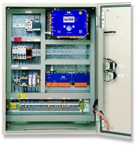
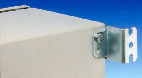
Figure 42:
There are holders on the control cabinets for wall mounting of the wall cabinets
Figure 41:
The control systems are supplied as installed in control cabinets for wall mounting, as floor standing cabinets or in door frames.
Assembly of the car terminal box
The car terminal box is attached to the car so that the switches for inspection and any sockets are easily and safely accessible and the trailing cable can be properly inserted.
Installation of absolute encoder system
The bp308 control system can be operated with different shaft-copying systems. Absolute encoder systems are usually used.
A pair of examples of standard systems are given below. They are adapted for bp308 control system and thus enable an uncomplicated commissioning. These systems can also be directly obtained from Böhnke + Partner.
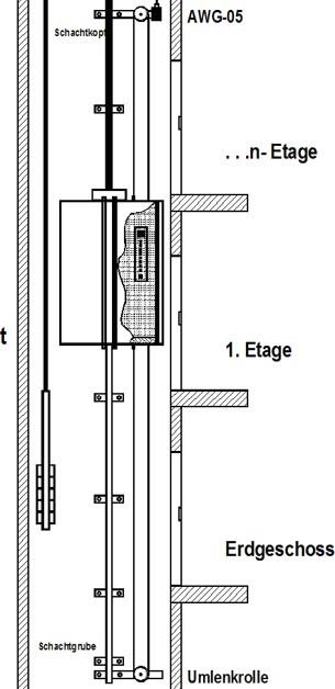
Overview of absolute encoder systems
The absolute encoder is installed as described in the installation manual supplied. The installation of AWG-05 tooth belt system is explained in more detail below.
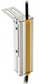
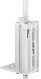
Absolute encoder AWG-05
The absolute encoder AWG-05 provides the position and speed of the car to all bus participants. The installation can be carried out on the shaft head or on the car. A tooth belt establishes a slip-free connection. Furthermore, an installation is possible on the speed limiter. In that case, the tooth belt can be omitted. However, a magnetic switch must be provided for correcting the belt slip. Please refer to the accompanying installation manual for the installation procedure.
-
Absolute encoder fastening sets
For installing the absolute encoder in the shaft or on the car there are different fastening sets for different use cases.
Type S 100
AWG-05 with fastening set “shaft” with tooth roller 5 mm wide, angular edges, conveyor height: max. 60 m, speed: max. 4.0 m/s
Type K 105
AWG-05 with fastening set “car” with tooth roller 5 mm wide, angular edges, conveyor height: max. 180 m, speed: max. 4.0 m/s
Tooth belt
Flat tooth belt – 5 mm, angular edges, black, for S 100, K 105
-
Installation in the shaft
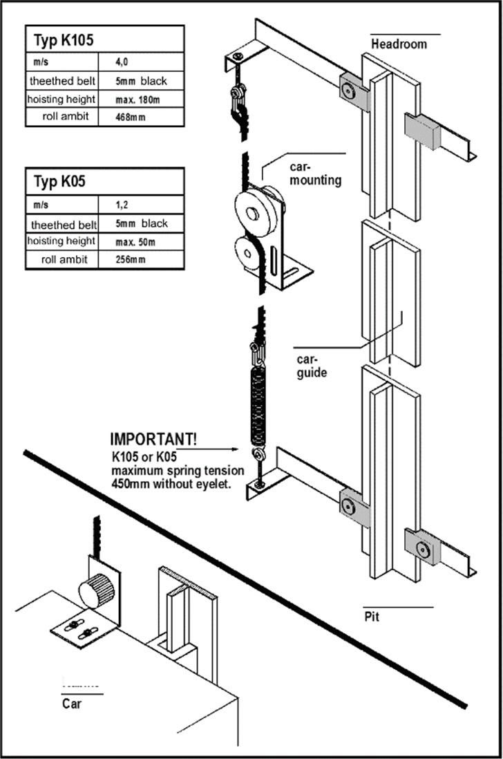
The AWG is attached to the guard rail in the shaft. It is driven by a tooth belt, which is connected to the car via a deviating roller in a slip-free way.
-
Installation on the car
Figure 43:
Fastening sets for installation in the shaft (type S100).
An alternative for the mentioned installation is the installation of the absolute encoder on the car. Here, a tooth belt stretched from the shaft head to the shaft pit drives the AWG. The advantage of needing lesser tooth belt is countered by the disadvantage that the tooth belt creates a rolling noise at high speeds when passing through the pulleys. It is effectively reduced by a special coating on the belt pulley.
Figure 44:
Fastening sets for installation on the car
-
Preparations
Before installing and commissioning this device, please read these safety instructions and warnings carefully and follow all the warning signs attached to the device. Make sure the warning signs are legible and replace missing or damaged signs.
WARNING! HAZARDOUS VOLTAGE!


- Make sure that you are not working on live devices. Deenergise the system (according to the circuit diagram).
- Before working on the lift control system, ensure that no voltage > 50 V AC is available.
- Plug must not be inserted if the corresponding devices are not switched off.
- Handling rules for sensitive electronic boards must be applied (protection against electrostatic charging).
- Before connecting to supply voltage, check whether the information on the identification plate of the control system conforms to the connection values.
- During the electrical installation, the general installation regulations must be followed. These include:
- VDE 0100 provision for setting up power installations with rated voltages up to 1000 V
- DIN EN 60204-1 (VDE 0113) Provision for electrical equipment of processing machines.
- DIN EN 50178 (VDE 0160) Equipment of power plants with electronic equipment.
- Statutory accident prevention regulations e.g. BGV A2.
- If the lift control system or associated components are used in special applications (e.g. area with potentially explosive atmosphere), the standards and regulations necessary therefor must be complied with.
- If an uninterruptible power supply (UPS) is present in the control system, switching off the main switch is not sufficient to deenergise the system. The UPS must be separately switched off.
![]()

-
Interference suppression measures and notes
All industrial, electronically controlled automatic control elements (PCs, microprocessors, computers, PLC) can be influenced by interference impulses if counteractive measures are not taken. These interference impulses can be generated by external systems such as voltage changes in supply line as well as control pulses of power elements of inverters. Böhnke + Partner GmbH takes into account all the usual measures when manufacturing the control system. The components used have low sensitivity to interference impulses of the surroundings.
The control systems have been designed for operation in industrial environments where high levels of electromagnetic interferences are expected. In general, a professional installation ensures safe and smooth operation. If any difficulties arise nonetheless, the following guidelines may prove useful. In particular, grounding the system reference potential (0V) to the control system, as described below, may prove to be effective.

You must keep these measures in mind:
- The control system bp308 exclusively helps for information processing in lift control system. All control signals are processed with positive switching logic or via the CAN bus. The safety guidelines of DIN EN 81 are not restricted by electronic information processing.
- The control system is designed, built and checked according to DIN EN 81 and VDE regulations. You must follow the relevant regulations for commissioning electric control devices and equipment. The local lightening protection measures are a prerequisite for operation. Circuit diagrams uniquely marked with a controlling number and technical documents are part of every control system.
- For all third-party devices, the manufacturer’s assembly and installation instructions must be followed exactly.
- To ensure compliance with the EMC guidelines, a suitable single-phase mains filter must be connected to the 230 V AC control circuit with the connected signal circuit.
- The control lines should be routed away from the load lines as far as possible using separate cable ducts. When intersecting, an angle of 90° should be maintained wherever possible.
- Control units are always connected using choke, filter and shielded cables according to the assembly and installation instructions of the manufacturer.
- Make sure that all devices in the cabinet are well grounded using short grounding wires with a large cross-section, which are connected to a common grounding point or ground rail. It is particularly important that each control unit (e.g. a speedometer) connected to a inverter is connected to the same grounding point as the inverter itself via a short cable with a large cross-section. Flat leads (e.g. metal holders) are preferred because they have lower impedance at high frequencies.
- Use shielded or armoured cables for the load connections between the drive and inverter or control system and ground the shield / armour at both ends.
- Data connections (group, DFÜ, printer port etc.) are generally established using shielded lines. The shield of the data lines should be earthed on one side.
- Mounting plates consist of galvanised steel plates in order to be able to produce large-area ground connections to all control components.
- Use of fail-safe components causes increased insensitivity to environmental influences.
- The car must be grounded by means of the green / yellow cable, which also leads through the travelling cable.
- The free travelling cable cores should be earthed on one side of the control cabinet.
- The components used in the control systems comply with the regulations of DIN EN 81 as well as VDE 0100 / 0101 / 0551 / 0660 and BGV A2. The control cabinets comply with the installation standard VDE 0660 / part 500.
- The main and auxiliary contactors used in the control system comply with DIN EN 81-20, 5.10.3 and VDE 0660, but at least device class D3.
- Voltage fluctuations that are within the tolerance range (+10%; -20%) of energy supply companies (RUs) are permissible.
- Malfunctions caused by an impermissible increase in voltage cannot lead to claims for damages against the manufacturer.
- If the user attaches additional coils (inductors) on his own initiative, it is of utmost importance that these are also suppressed.
- For DC-powered inductors such as contactors, relays, brake magnets, bolt magnets and hydraulic valves, always place a diode (1000 V / 1 A) anti-parallel and as close as possible to the coil. (Free-wheeling diode at Böhnke + Partner GmbH)
- For AC-powered contactors, relays, brake magnets, bolt magnets and hydraulic valves, it is always necessary to install an RC combination, matched to the coil type, parallel and as close as possible to the coil. (RC combination of Böhnke + Partner GmbH can be used universally.)
- In the case of three-phase powered door drives, brake and bolt motors, an RC combination matched to the motor type must always be installed parallel and as close as possible to the motor winding. The RC combinations are connected to the motor windings in star formation (RC combinations of Böhnke + Partner GmbH can be used universally.)
- Interference suppression measures must be installed practically.
Figure 45:
Circuit diagrams for interference suppression measures
-
Connections for cable shields
In order to achieve a good electromagnetic compatibility (EMC) of the lift system, all shielded cables must be connected as shown in the figures below, unless they have been assembled as EMC-compliant plug connections.
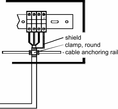
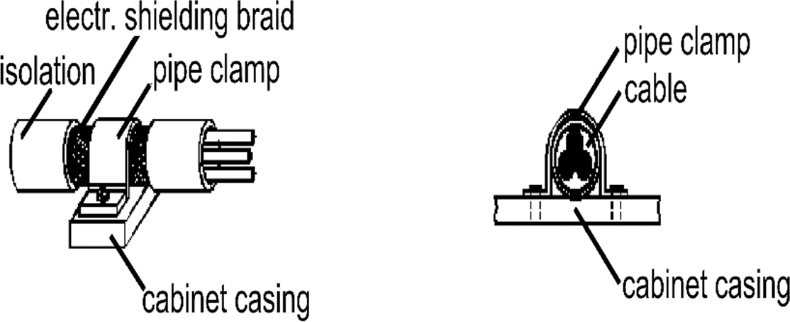
Figure 46: Connection example for shielded cables
Figure 47:
The shields must always be connected to the entire surface of PE potential by means of cable or pipe clamp.
-
Names in circuit diagrams
Böhnke + Partner GmbH defines the names of the individual components according to function groups. We refrain from forcing the names into a rigid scheme. By using the CAD system to create the circuit diagrams, we achieve greater flexibility when labelling in the circuit diagrams and in the parts lists. Each component is named directly in the circuit diagrams, based on the function and project, and thus is customised.
-
Safety circuit

The safety circuit is designed, for example, for monitoring the following external signals:
- Closed position of maintenance and emergency doors,
- Locking of car doors,
- Locking of shaft doors,
- Closed position of shaft doors,
- Closed position of car doors,
- Emergency stop car roof, car and control room,
- Speed limiter,
- Buffer contacts,
- Emergency limit switch top and bottom,
- Safety gear,
- Door zone with safety circuit.
The doors and bolts are monitored for retracting with the doors open and for levelling within the door zone. All travel and auxiliary contactors for the safety circuit are designed in accordance with VDE 0660, device class D3. The signal voltage for the safety circuit is max. 230 V AC.
The safety circuit works independently of the control system bp308. In the event of a malfunction, the operating voltage of the output module for the control elements is switched off.
Figure 48:
Standard switching of the safety circuit in the example of bp308
-
Electrical installation
After mechanical assembly of all components, carry out the electrical installation using the circuit diagrams provided. Ensure proper connection of all terminal points and compliance with EMC wiring guidelines.![]()

-
Cable entry control cabinet
The control systems are installed by Böhnke + Partner in control cabinets which are qualified for use for protection class IP54 (in accordance with IEC/EN 60529).
This protection class remains unchanged if the required cables are inserted through a correctly made opening in the foam rubber seal on the bottom side of the control cabinet.
For the insertion of the travelling cable it is recommended to make a smooth cut with a suitable tool in the foam rubber seal with a length of approx. 5 cm (slightly smaller than the width of the travelling cable) and to insert the ready-made travelling cable through this.
For round cables it is recommended to drill a hole with a diameter of the cable in the foam rubber seal. This hole should then be extended by a smooth cut (possibly cross-cut for very wide plugs) in the length of the plugs of the ready-made cable.


![]()
![]()
![]()
![]()
![]()
![]()
![]()
![]()
![]()
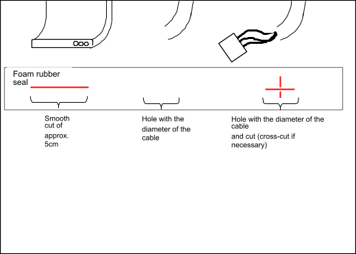
Figure 50:
Cable entry control cabinet
-
Bus connections

The bp308 control system uses the CAN bus according to the application profile CiA 417. This profile also describes the physical parameters of the bus lines and the topology. Special regulations generally apply for the wiring of bus systems.
-
Electrical bus medium
Figure 51:
Lift components that comply with the application profile CiA 417 must bear this logo.
The components according to CiA 417 require a two-wire line for communication. From the point of view of the bus, the individual connected components are referred to as nodes. The nodes are connected in parallel to the bus. While doing so, it must be ensured that the topology of the bus line always forms a line.
The CAN high-speed standard (ISO11898-2) requires that the bus be terminated at the beginning and at the end with a resistor (120 ohms). Termination can be done in different ways. For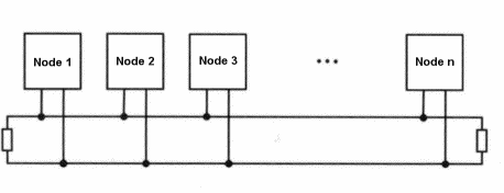
some nodes, an internal resistor can be activated via a DIL switch or jumper, and for others, a resistor must be connected to the bus
terminals. For exact termination, refer to the manuals of all connected nodes!
Figure 52:
The bus must be terminated at the beginning and end with a 120 ohms resistor.
The maximum number of nodes on the bus is limited to 64 nodes by the driver blocks used. If more nodes are required, repeaters or bridges must be used (see further below).
Furthermore, the baud rate of all connected nodes must be equal. As network master, bp308 provides a baud rate of 250 kBit to the interfaces CAN1 and CAN2. All other components of Böhnke + Partner GmbH have an automatic baud rate detection or are preset at 250 kBit. For the baud rate used, the bus must not exceed a length of maximum 200 m. The transmission lines in total must not be longer than 3 m.
-
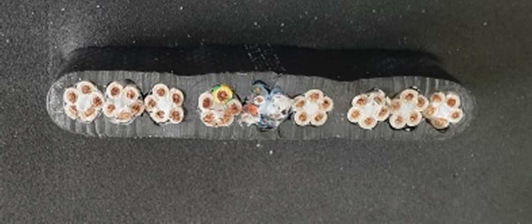
Cable colours
The cable colours for bus lines are not defined in CANopen Lift. To facilitate wiring and fault-finding, we recommend using the following colours for the bus lines:
|
Signal |
Description |
Colour |
|
CAN_L |
CAN-Bus-Signal (dominant low) |
blue |
|
CAN_H |
CAN-Bus-Signal (dominant high) |
white |
|
GND |
External ground |
black |
|
CAN_V+ |
External voltage supply (+24 V) |
red |
-
Network topology

Bus systems dictate a topology based on the laws of physics. For the CAN-Bus used, a line structure is dictated in the specification CiA 417.
This cable routing is not always feasible in practise. Therefore, additional lines can be connected via repeaters. Note that each section behind a repeater is an independent bus and must therefore be terminated at the beginning and at the end.
Figure 53:
Lines can be connected using repeaters:
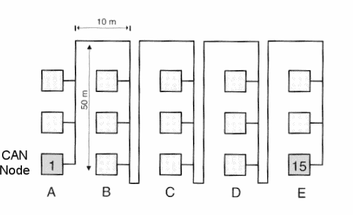
Figure 54:
The wiring of all nodes must always form a line.
-
Examples for a correct topology
-
Individual control system
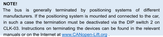
In figure 48, you can see an example for compliance with line structure and termination in an individual control system. The car bus is shown in blue and the group bus in red. If the transmission line to the inverter is shorter than 3 m, termination can also take place in bp308. Termination on the car takes place either using a connected AWG or the DIP switch (DIP 2 at “on”) on CLK-03. The group bus is ended at the shaft end by default by activating termination at the DIP switch of the last CAP-01/02 (DIP 2 at “on”).
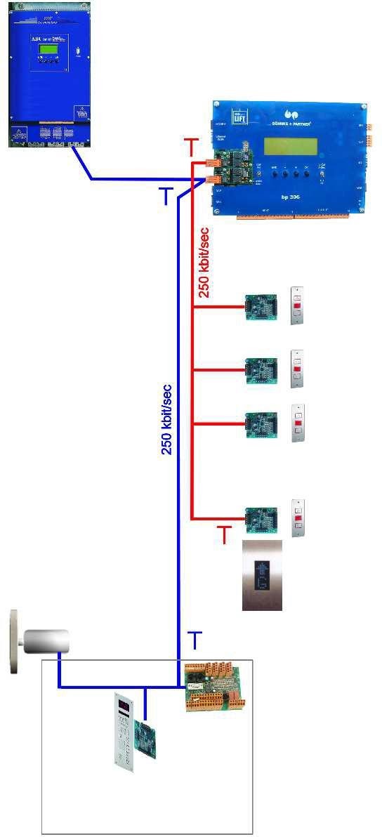
Figure 55:
Example for the topology of an individual control system.
-
Two-part group with a line
Figure 49 shows the bus topology of a two-part group with one line for landing calls. Here, too, the line structure is adhered to and the bus is terminated at the ends.
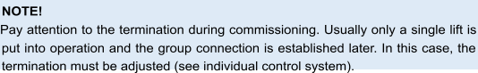
Figure 56:
Example of the topology of a two-part group with only one line
-
Two-part group with two lines
Figure 50 shows the bus topology of a two-part group with two lines for landing calls. By terminating at the two shaft ends, the line structure is maintained.
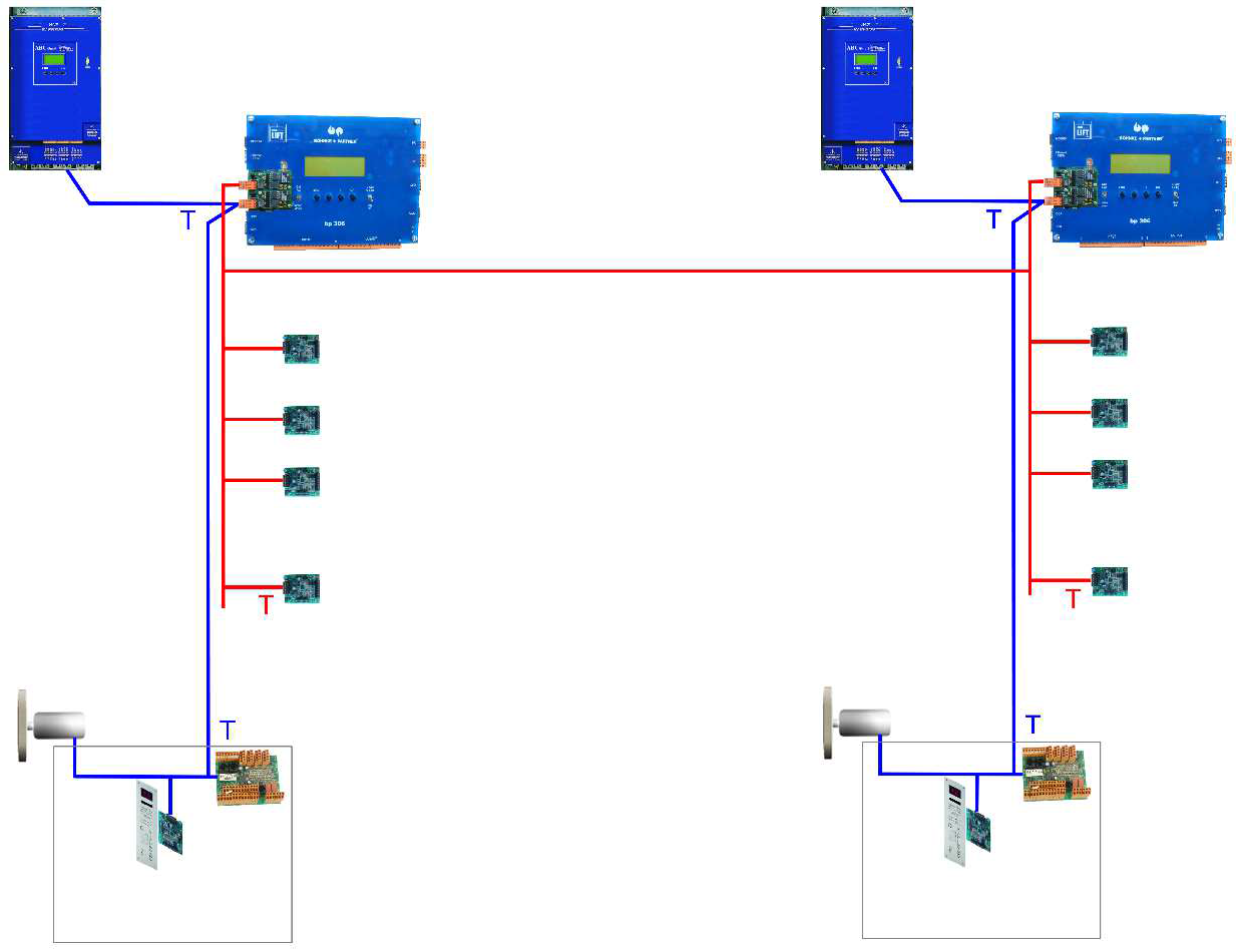
Figure 57:
Example of topology of a two-part group with two lines
-
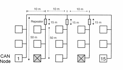
Two-part group with three lines
Figure 51 shows the bus topology of a two-part group with three lines for landing calls. Since a line structure can no longer be adhered to with more than two lines, bridges are used here. Thus, each cable in turn forms an independent line. The bus is terminated at each end.
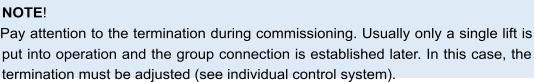
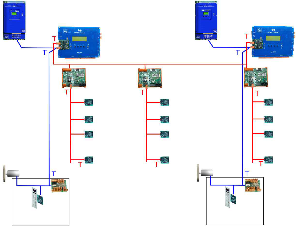
Figure 58:
Example of topology of a two-part group with three lines
-
Connector pin assignments
In the CANopen Lift Standard the assignments of the most common connectors are standardised. In the application profile for lifts the following connectors are recommended for lift components:
- D-Sub 9-pin
- RJ45
- Open-Style plug
|
Figure |
Pin |
Signal |
Description |
|
D-Sub plug 9-pin
|
1 |
– |
Reserved |
|
2 |
CAN_L |
CAN-BUS-Signal (dominant low) |
|
|
3 |
CAN_GND |
CAN ground |
|
|
4 |
– |
Reserved |
|
|
5 |
CAN_SHLD |
Optional shield |
|
|
6 |
GND |
Optional ground (from Pin 9) |
|
|
7 |
CAN_H |
CAN-BUS-Signal (dominant high) |
|
|
8 |
– |
Reserved |
|
|
9 |
CAN_V+ |
Optional external voltage supply (+ 24 V DC) |
|
Figure |
Pin |
Signal |
Description |
|
RJ45 socket
|
1 |
CAN_H |
CAN-BUS-Signal (dominant high) |
|
2 |
CAN_L |
CAN-BUS-Signal (dominant low) |
|
|
3 |
CAN_GND |
CAN ground |
|
|
4 |
– |
Reserved |
|
|
5 |
– |
Reserved |
|
|
6 |
CAN_SHLD |
Optional shield |
|
|
7 |
GND |
Optional ground |
|
|
8 |
CAN_V+ |
Optional external voltage supply +24 V DC |
|
Figure |
Pin |
Signal |
Description |
|
Open-Style plug
|
1 |
CAN_GND |
CAN ground |
|
2 |
CAN_L |
CAN-BUS-Signal (dominant low) |
|
|
3 |
CAN_SHLD |
Optional shield |
|
|
4 |
CAN_H |
CAN-BUS-Signal (dominant high) |
|
|
5 |
CAN_V+ |
Optional external voltage supply (+24 V DC) |
-
Node numbers of CAN components
Each CANopen Lift component has a node number (Node-ID) for identification. It must be unique within a CANopen Lift network. If there are two components with the same ID on the bus, these components cannot be approached.
At Böhnke + Partner GmbH, the node numbers (Node-ID) are issued according to the recommendation of the SIG-Lift Control (www.CANopen-Lift.org/wiki/Node-IDs) according to the following scheme:
|
Node-ID [decimal] |
CAN1 Local bus |
CAN2 Shaft bus |
|
1 |
bp308 – lift control system |
bp308 – lift control system G1 |
|
2 |
Drive (frequency inverter) |
bp308 – lift control system G2 |
|
3 |
reserved |
bp308 – lift control system G3 |
|
4 |
Transmitter/positioning 1 |
bp308 – lift control system G4 |
|
5 |
Transmitter/positioning 2 |
bp308 – lift control system G5 |
|
6 |
reserved |
bp308 – lift control system G6 |
|
7 |
Door control system 1 (door A) |
bp308 – lift control system G7 |
|
8 |
Door control system 2 (door B) |
bp308 – lift control system G8 |
|
9 |
Door control system 3 (door C) |
CDG-01 /CSI-01 – Bridge / Repeater |
|
10 |
CDG-01 – Gateway / CSI-01 – Bridge |
Bridge / Repeater 2 |
|
11 |
CIO-01 in control cabinet |
Bridge / Repeater 3 |
|
12 |
Inspection box with CLK-03 |
Bridge / Repeater 4 |
|
13 |
Load measurement |
Bridge / Repeater 5 |
|
14 |
Energy meter |
Bridge / Repeater 6 |
|
15 |
reserved |
Bridge / Repeater 7 |
|
16 |
CAP-02 / CBK-01 inner tableau node 1 |
Bridge / Repeater 8 |
|
17-20 |
CAP-02 / CBK-01 inner tableau nodes 2 – 5 |
|
|
21-84 |
CAP-02 / CBK-01 / CIO-01 in shaft |
|
|
111-118 |
CAP-02 / CIO-01 in control cabinet |
|
|
119 |
CWI-01 |
|
|
125 |
Default Node-ID (default setting of a bearing component such as wie CAP-02, CBK-01 or CIO-01) |
|
|
126 |
Flash update of bootloader |
|
|
127 |
CANWizard |
If you obtain the control system from Böhnke + Partner GmbH, all node numbers (Node-IDs) are already set by default.
-
Flat travelling line to car terminal box
The cabin terminal box is connected via a H05VEA7VH6-F flat travelling line. The assignment of the wires can be found in the circuit diagrams enclosed with the control system.
-
Activation of inverter
There are three ways to activate an inverter using bp308. Depending on the selected inverter, it can be activated via the CAN bus, the DCP interface or parallel wiring with the RVM-01.
-
Activation via CAN-Bus
If you have an inverter with a CANopen Lift interface according to the application profile CiA 417, the connection to the bp308 should be made via the CAN bus. This activation of the inverter requires the least installation and configuration effort, since the standardised application profile provides a certain plug-and-play capability and excellent diagnostic capabilities.
Connect the inverter to the CAN1 connection of the bp308 according to the enclosed plans. When routing and terminating bus lines, observe the instructions in section 7.9.4.
-
DCP-connection to inverter
The DCP interface is used for the serial connection between the inverter and the control system. The connection is a RS-485 point-to-point connection.
The DCP interface is on the right side of the bp308 (see designation SP3, 3-pin connector). The pin assignment can be found in the following table.
Pin assignment of DCP plug
|
Pin |
Signal |
Description |
|
5 |
COM |
Signal ground |
|
6 |
B |
Signal line RS-485 inverted |
|
3 |
A |
Signal line RS-485 |
Connect the signal lines to the inverter using the corresponding connection terminals. The cable must be twisted and shielded. The shield must be placed on one side of the inverter. Here, it is important to ensure a large-area connection (see chapter 7.3). The maximum cable length for the DCP connection is 15 m.
-
Parallel wiring with RVM-01
The controller pilot-control module “RVM-01” is used to control all known inverters that do not have the option of serial control. The control signals for the various speeds and directions are displayed potential-free via seven relays. These have gold-plated double contacts to ensure reliable switching for all expected requirements.
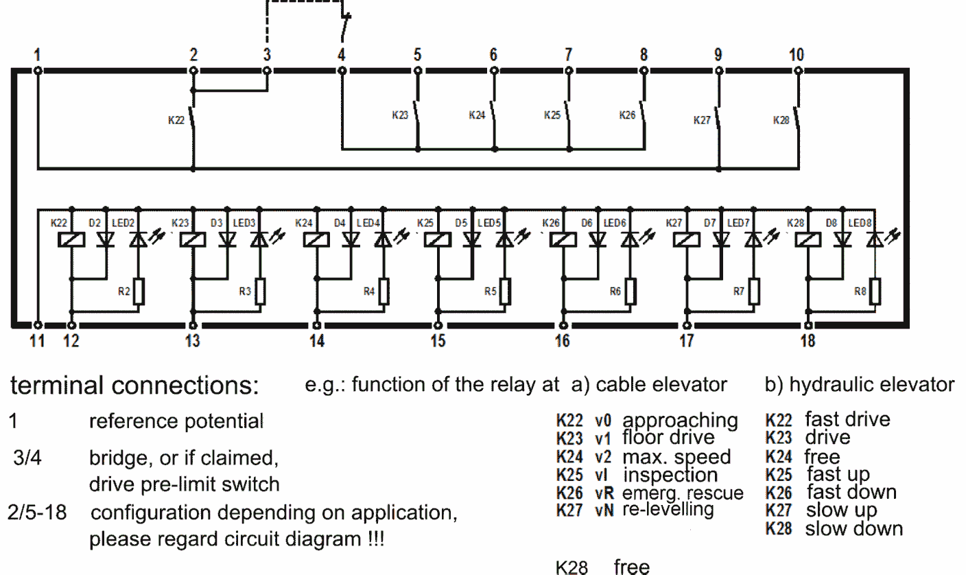
Figure 59:
Circuit of RVM-01
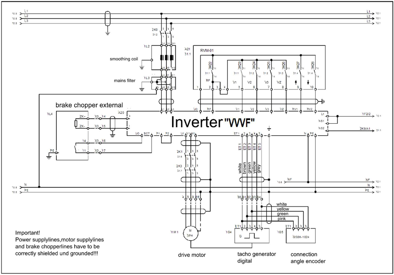
Figure 60:
Example of an inverter control with RVM-01.
Control inputs like in example see figure 53:
GND Ground
UO Control voltage of inverter
Voltage output for controlling inputs
RF Controller release, the input “RF” must be controlled during the travel. V0 Entry speed
V1 Positioning speed
V2 Intermediate speed
V3 Travel speed
VR Retaining / inspection speed
VN Levelling speed
RV1 Direction specification 1 UP RV2 Direction specification 2 DOWN
If the inverter is connected according to the suggested circuit, the motor in the factory setting rotates on the left with activated input “RV1”, on the right with “RV2” (view of the travel end of the shaft).
ZE1 Additional speed V_ZE
ZE2 Additional speed V_ZE2
Preferably, these speeds must be used for inspection travel and return control.
ZE3 Additional speed V_ZE3
This input can trigger various functions in the inverter. The setting is carried out in the menu INTERFACES. The additional speed V_ZE3 having the same name is selected ex works.
BCT Brake chopper temperature.
At this input, the temperature switch or the fault output of the brake chopper is monitored.
-
Connection of absolute encoder (AWG)
The absolute encoder is designed with a 9- pin D-sub connector. The pin assignment complies with the standard of CANopen Lift. The CAN-Bus is terminated in AWG – 05 CANopen Lift. If the absolute encoder is located on the car, the connection cable can be plugged directly into the socket on the CLK. If the absolute encoder is located in the shaft head, the connection cable can be plugged into the correspondingly labeled absolute value encoder socket in the control cabinet.
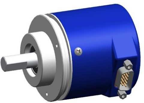
Figure 61:
The absolute encoder AWG-05 CANopen Lift can be installed in the shaft head or on the car.
-
Group connection
The group connection is used to communicate between the individual control systems and to transmit the shaft signals. The interface for the group connection is the “CAN2” connection.
The data lines must be twisted. They are led down from the connection terminals to the terminal block of the control system. The connection to the other group participants is done via a connector.
The lines with the shaft signals are connected as described in the chapter “Topology”. If the shaft signals are conventionally laid for control system, they are replaced by components, e.g. of type CAP-01/02 or CIO-01, converted into CANopen lift data.
-
Data lines for remote diagnosis
The remote diagnosis can be done via different media. There are different rules for each.
-
Analogue telephone line
If an analogue telephone connection is available for the remote diagnosis, the data transfer takes place with an analogue modem. An analogue modem can be connected to the USB-A port of the bp308. It must be a “real” hardware modem and not a softmodem. The USB modems supplied by Böhnke + Partner GmbH for bp308 are “real” hardware modems. Furthermore, the modem must support V.250 standard. If several control systems share a common telephone line or if an emergency call system is available, which also uses the analogue telephone line, an emergency call manager must be appounted (see chapter Connection of the emergency call system).
-
Ethernet
If remote diagnostics is to be carried out via an intranet or the Internet, an Ethernet- connection is usually available in the machine room. In this case, use the LAN port of bp308.
-
Connection of the emergency call system
Emergency call devices ususally require a telephone connection. If a separate connection is available for the emergency call system, the wiring is as specified in the description of the emergency call system. Mostly, however, the emergency call system has to share the telephone line with the modem of the control system. In this case, it must be ensured that the emergency call system has priority. Some emergency call systems provide a switched-through connection for a remote diagnosis system as long as there is no emergency call. If such a connection to the emergency call system is not available, a so-called emergency call manager must be appointed. He immediately interrupts an existing remote diagnosis connection when an emergency call occurs and makes the telephone connection available to the emergency call system. There is no general scheme for connecting an emergency call system. Therefore, refer to this information from the enclosed circuit diagrams and the documentation of the emergency call syst

.

During the acceptance test, the “Technical Information” (section 8.3) must be observed.
-
Preparations
During commissioning on site, no measuring instruments are required except a universal measuring device.
8.1.1 Before first switch-on
According to VDE 0100 and EN 81, the power circuit must be earthed. The terminal “PE” of the control system is therefore always connected to the power supply via a green / yellow cable.
-
Technical information about the control system
- Smooth and safe operation of the product requires proper transport, storage, setup and assembly as well as careful operation and maintenance.
- The control system is designed, built and checked according to DIN EN 81 and VDE regulations. You must follow the relevant regulations for commissioning electric control devices and equipment. The local lightening protection measures are a prerequisite for operation. Circuit diagrams uniquely marked with a controlling number and technical documents are part of every control system.
- The control system bp308 exclusively helps for information processing in a lift control system. All control signals are processed with positive switching logic. The safety guidelines of DIN EN 81 are not restricted by electronic information processing.
- The control system bp308 has received an EU-type examination certificate from notified bodies. Section 3.1 lists the EU type examination certificate and chapter 3.3 the EU declaration of conformity within the meaning of EU Directive (2014/33 / EU), which shows that the assembly we use complies with the regulations.
- The components used in the control systems comply with DIN EN 81 as well as VDE 0100 / 0101 / 0551 / 0660 and BGV A2. The control cabinets comply with the installation standard VDE 0660 / part 500.
- The main and auxiliary contactors used in the control systems comply with DIN EN 81-20, 5.10.3 and VDE 0660, but at least device class D3.
- Voltage fluctuations that are within the tolerance range (+10%; -20%) of energy supply companies (RUs) are permissible.
- Malfunctions caused by an impermissible increase in voltage cannot lead to claims for damages against the manufacturer.
- Special features when using an uninterruptible power supply (UPS) must be observed. Before commissioning the connected UPS, read the operation manual. The UPS must ensure supply to all necessary control functions.
Regularly check the functioning and smooth use of UPS. The instructions of the device manufacturer must be followed.
- Insulation and short circuit measurement:
- An attenuation filter is installed in all control systems. The attenuation filter can get destroyed during insulation measurement. Before carrying out insulation measurement in the safety circuit, the control fuse must be removed.
- For all control systems in which a UPS is installed, this UPS must be completely disconnected before the insulation or short-circuit measurement and the connections must be bridged in the control system accordingly.
- Follow the usual safety regulations during insulation measurements. There is danger for man and machine.
- All relays and contactors installed in the control systems must be suppressed (see section 7.2).
- The motor circuit-breakers, excess current release, RCD circuit breaker, etc. installed in the control systems are supplied by default and must be checked during commissioning and, if necessary, adapted to the connected equipment.
- The neutral conductor of the power supply of the safety circuit must be connected to terminal 9 of bp308; the neutral conductor of the main contactors must be connected to terminal 14 of bp308.
- According to VDE regulations, the ground line (V DC) must be connected to the protective conductor (PE) of the mains supply.
- The terminal (100) (ground) is connected to the terminal PE (protective conductor) in the control system. As a result, there is no floating network and an earth fault of the signal voltage (+24 V DC) is detected immediately.
- Transformers are grounded on one side on the secondary side (e.g. special voltages of the brake or the valves). As a result, there is no
floating network and an earth fault of the secondary voltage is detected immediately.
- Terminals 20A and 20C (+24 V DC max. 2.2 A) of bp308 are monitored with regard to overload and short-circuit. Overload is signalised by the LCD
- The safety circuit with the monitoring unit in bp308 is protected with max. 1 A (in exceptional cases with a maximum of 2 A).
- The impulse diagram for the control system must be observed. The impulses listed there are not drawn to scale. It is a schematic representation.
- The arrangement of the shut-down points in the levelling area (levelling zone) must be strictly adhered to.
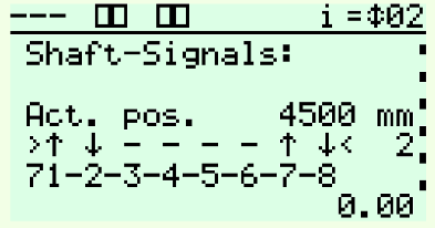
- The signals of the impulse generators and level switches can be checked during travel, inspection and emergence control mode in the service menu under Shaft Signals on the LCD display.
- During maintenance and inspection work, it is possible to keep the car door closed on the landings. See service menu Maintenance on the LCD.
- For monitoring work, the car can be moved to the end stops via the call menu: press upwards: Travel towards end stop above,
press downwards: Travel towards end stop below,
- During inspection drive the terminals E1 (101), E17 (401) or (801) at bp308 or CLK-03 de-energised (see DIN EN 81-20, 5.12.1.5):
- all car and landing calls are deleted and blocked,
- door opening is prevented, no automatic door movement,
- the fast travel is automatically delayed at the correction switch,
- the drive is switched off at the level switch of the final stop,
- the levelling equipment is switched off,
- the return device for hydraulic lifts is not effective.
- The return motion control system is not effective.
- During emergency control mode the terminal E2 (102) at bp308 is de- energised (see DIN EN 81-20, 5.12.1.6):
- all car and landing calls are deleted and blocked,
- door opening is prevented, no automatic door movement,
- the fast travel is automatically delayed at the correction switch,
- The level switch of the end stop can be overrun during emergence control mode!
- See service menu “Maintenance” on the LCD.
- the levelling equipment is switched off,
- the return device for hydraulic lifts is not effective.
- If the emergence control mode and the inspection drive are “simultaneously activated”, the car cannot move.
- After switching off the landing control via the menu item “External control system off”, all car and landing calls are deleted. Landing calls are no longer accepted. Car calls are continued to be accepted.
- The parking landing remains ineffective if the landing control is switched off.
- The failure of the lighting voltage is monitored by the control system. A travel that has begun is terminated and the car stops with the door open. A new travel is prevented.
Hydraulic lifts lower for return landing.
The inspection or return motion control system remain in operation.
The levelling equipment continues to remain in operation (see EN 81- 20,5.4.10).
- The motor is protected by PTC resistor monitoring (PTC) with PTC resistor wrapped in the windings of the three-phase motor. The monitoring circuit integrated in the bp308 control system controls the motor operating temperature.
- The PTC threshold values are monitored and processed by a sequential circuit.
- Temperature normal value <2.2 kOhm = normal operation,
- Temperature too high value > 2.7 kOhm = PTC resistor has tripped,
see malfunction messages
Settings in the setup menu:
Rope traction lift
Stop immediately without a block
Stop at the next level switch without block Stop immediately with block
Stop at the next level switch with block hydraulic life
Stop with return without block Stop without return without lock Stop with return with lock
Stop without return with lock
- The malfunction message is entered into the stack memory and the malfunction list when the motor operating temperature is exceeded. If remote
monitoring is connected, the malfunction is immediately reported to the service center.
- The return to the lowest station in normal mode in case of hydraulic lifts, i.e.: all safety functions are OK,
- is automatically initiated after the set time (max. 15 min.).
- the return immediately ends after the control system is sqitched off (e.g. remote off).
- takes place automatically after switching off the landing control after the set time (max. 15 min.).
- In all cases a), b) and c) the subsidence correction system continues to operate (see EN 81-20, 5.12.1.10).
- Upon arrival at the lowest stop, the lift door will open and close in all cases a), b) and c). The button “Door open” always remains active.
- The car light can be switched off quietly with lift doors closed; freely adjustable. The car light is switched on immediately during operation.
- If the upper emergency limit switch is actuated in hydraulic lifts, the lift will stop immediately. If the car is released again by subsequent lowering, all normal functions are switched off and the return to the lowest stop takes place immediately when the safety circuit is closed. The car remains at the lowest stop with call acceptance locked after the door opens and closes. The button “Door open” always remains active.
- The subsidence correction system continues to remain in operation (see EN 81-20, 5.12.1.10).
- In case of hydraulic lifts, the shafting correction system is activated upon activation of the runtime control and the lift is locked immediately.
- In case of hydraulic lifts, the start-up control is requested as follows:
- Start-up control during upwards movement activates an automatic return to the bottommost stop with lock. Should the runtime control be activated outside the zone, the lift will lock immediately and the shafting correction system will not be activated, since the »Start-up control Up« has been registered as the first malfunction.
- In case of downward start-up control, the lift locks immediately. The shafting correction system continues to remain in operation.
- In case of overload, the shafting correction system in hydraulic lifts remains in operation.
- The request of the input for overload exclusively takes place when stationary.
- An excess pressure switch on a hydraulic lift is connected and requested to terminal 50. In the setup menu, the corresponding parameters can be set according to the required function (»Excess pressure On«, »With lock« or

»Without lock«).
- An emergency control (similar to the return control “Only Up”) can basically be installed on a hydraulic lift. If an emergency control is integrated, the following switches may be bypassed: Low pressure, burst pipe, emergency limit switch below and the clamp.
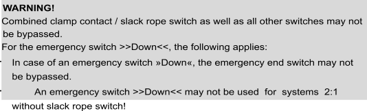
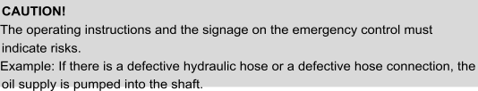
- All requirements set by the “WHG-Water Resources Act” for the hydraulic lift must be met.
- The runtime monitoring is available as standard for all control systems. To check the function, you must do the following (EN 81-20, 5.9.2.7 and 5.8.3.10):
Magnetic switch copying
- Travel the car to the bottommost stop,
- Disconnect impulse generator on S75 or S77,
- Give landing call to the topmost stop,
- the car goes past the impulse generators without a clear signal transfer taking place,
- after the set time (up to 45 s), the electronic monitoring device of the control system automatically switches off the drive,
- the control system is subsequently locked for further travels (see the information on the LCD),
- Disconnect impulse generator on S75 or S77 again,
- To unlock, press the call button (»Call/End«) and confirm with »OK«. Alternatively, switch off the control system and switch it on again.
- The control system is ready for operation again.

Absolute encoder copying
- Travel the car to the bottommost stop,
- in the control system (LC display), reduce the time for the runtime control according to the travel speed,
- Give landing call to the topmost stop,
- the car does not reach the next impulse in the travel control time,
- after the set time, the electronic monitoring device of the control system automatically switches off the drive,
- the control system is subsequently locked for further travels (see the information on the LCD),
- in the control system (LCD), set the time for the runtime control according to the travel speed,
- To unlock, press the call button (»Call/End«) and confirm with »OK«. Alternatively, switch off the control system and switch it on again.
- The control system is ready for operation again.
- When the runtime monitoring is activated, the shafting correction system remains in operation on hydraulically-driven lifts.
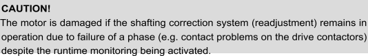

.
- In order to save the individual inputs of the lift system, open the menu option Save system data parameters in the setup menu under Miscellaneous
- To complete the entries, please press »OK« after making the changes and return to the basic view of the display.
-
Checklist before switching on the control system


|
A weight compensation has taken place between car and counterweight. |
Yes □ |
|||||||||
|
The mechanical brake is set. |
Yes □ |
|||||||||
|
The car is (at least 1 m). |
located |
at |
a |
sufficient |
distance |
from |
the |
limit |
switches |
Yes □ |
|
The mains voltage of 3 x 400 V AC is available. |
Yes □ |
|||||||||
|
Buffers are installed and functional. |
Yes □ |
|||||||||
|
Speed limiter and safety gear are installed and functional. |
Yes □ |
|||||||||
|
Safety circuit contacts of shaft and car are installed and connected. |
Yes □ |
|||||||||
|
Have you observed and applied the safety instructions in the chapter “Safety instructions”? |
Yes □ |
|||||||||
|
A control system of Böhnke + Partner GmbH includes:
EU Type-examination certificate and Certificates of conformity for the system module bp308,
Are these documents completely available? |
Yes □ |
|||||||||
|
Have you followed the circuit diagrams that belong to the control system? |
Yes □ |
|||||||||
|
Have you observed and applied the interference suppression measures in the chapter “Interference suppression measures”? |
Yes □ |
|||||||||
|
Has the correct connection and secure fit of all clamping points been checked? |
Yes □ |
|||||||||
|
Is the main switch switched off? |
Yes □ |
|||||||||
|
Is the voltage test module STM-02 connected (see chapter 8.2)? |
Yes □ |
|||||||||
|
Check the power supply. Are L1, L2, L3, N and PE correctly connected (clockwise- rotating field)? |
Yes □ |
|
Is the wire cross-section chosen according to the power consumption of the lift? |
Yes □ |
|
If a fuse switch is available, are the permissible fuse links fitted? |
Yes □ |
|
Is the automatic circuit breaker for the control voltage switched off? |
Yes □ |
|
Is the circuit breaker for the safety circuit switched off? |
Yes □ |
|
Are the supply lines correctly secured? |
Yes □ |
|
If a high-speed brake excitation is available, are the circuit breakers switched on? |
Yes □ |
|
The motor protection switches, overcurrent releases, Residual Current-operated protective Device (RCD) circuit breakers , phase monitors, etc. installed in the control system can only be preset by Böhnke + Partner GmbH and must be adapted to the connected equipment during commissioning by you. Have you made the adjustments? |
Yes □ |
|
Are all protective conductors connected correctly? |
Yes □ |
|
Have you followed all the interference suppression measures and EMC instructions of the inverter manufacturer? |
Yes □ |
|
Did you follow the commissioning instructions of the control system and the drive? |
Yes □ |
|
Is the return control switched on? |
Yes □ |
If you have responded to all questions with »Yes«, then you may switch on the mains voltage in compliance with the following chapters.
-
Connecting the mains voltage
If you have answered “Yes” to every question in the “Checklist before switching on the control system”, you can switch on the mains voltage. Subsequently check the items in the following checklist.
|
Is the main switch switched on? |
Yes □ |
|
Is the return control switched on? |
Yes □ |
|
Is the automatic circuit breaker for the control voltage switched on? |
Yes □ |
|
Is the circuit breaker for the safety circuit switched on? |
Yes □ |
|
Has no protective device been triggered? |
Yes □ |
|
Doesn’t the STM-02 voltage test module give an audible or visual warning signal? |
Yes □ |
|
Does the LCD display on the bp308 system module report any voltage problems? |
Yes □ |
|
Is the voltage at the power supply between terminals L and N 230 V AC? |
Yes □ |
|
Is the voltage at the power supply in the control cabinet terminal +24 compared to terminal 0 equal to 24 V DC? Are the car operating panel and CLK supplied with 24 V? |
Yes □ |
|
The LCD light is not flashing? (System would be blocked.) |
Yes □ |
|
Is the colon of time on the LCD of the bp308 flashing? |
Yes □ |
|
Is car light voltage at the X92.LN and X92.3 = 230 V AC? |
Yes □ |
|
Do the LED(s) for 5 V and 24 V operating display glow, on the external power supply, if available? |
Yes □ |
|
Is the RHS symbol displayed on the display of the bp308 (return control active)? |
Yes □ |
If you have answered all questions with »Yes«, then you can proceed with checking the parameters of the control system and of the drive.
-
Checking the parameters of control system and drive
After the mains voltage has been switched on correctly and no clear errors can be detected, the set parameters of the control system and the drive are checked.
To check the drive, refer to its commissioning documentation.
The control documentation includes a printout of all parameters set by Böhnke + Partner GmbH. Check if they match the local conditions. If necessary, the parameters must be adjusted accordingly on the display of the bp308 (see User Manual bp308).
-
Checking the bus lines
A first indication of the function of the CAN bus is provided by the diagnostic LEDs, which are located to the left of the display next to the corresponding connector. Each bus connection has an Error LED flashing in red and a Run LED flashing in green on the board. These LEDs indicate current malfunctions and operating states of the respective bus. The following table shows the status of the LEDs and their meaning. During the system start-up, both LEDs are active for a short time.
|
CAN-ERROR-LED |
State |
Meaning |
|
|
off |
CAN-Bus: no errors or interface deactivated |
|
1 impulse |
CAN-Bus: Warning |
|
|
2 impulses |
CAN-Bus: Malfunction |
|
|
on |
CAN-Bus: Bus-Off (out of operation, Auto-Reset after approx. 10 s) |
|
|
Flashing |
Node-ID error: double Node-ID in the network |
|
CAN-RUN-LED |
State |
Meaning |
|
|
off |
CAN-Bus: Interface deactivated |
|
2 impulses |
CAN-Bus: Monitor active |
|
|
Flashing |
CAN-Bus: Setup menu active |
|
|
on |
Normal operation |
-
Checking the termination
As described in chapter “Bus connections”, the bus must be terminated at both ends. Verify that the car bus and the group bus are terminated at both ends.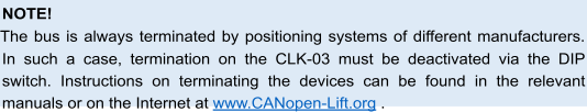
-
Checking the CAN parameters
To check the CAN parameters in the control system, go to the setup info or the setup menu of the control system. Under
PARAMETERS → TERMINALS → TERMINAL CAN1 / 2
, you will find a list of all connected CAN devices.
Check if the devices used in your system are activated. Since the CAN devices are preconfigured when you receive the control system from us, no further parameterisation is necessary at this point.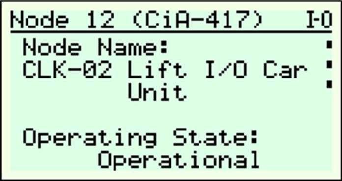
If you are assembling a control system
made up of OEM components, you can optionally receive a USB-CAN adapter for the PC and the »CANwizard®« software for the parameterisation of the CAN devices. However, configuration of the input/output terminals is also possible via the control display. Information about the CANwizard® and the configuration of the devices can be found in the CANwizard®manual or on the website www.CANwizard.de. If all devices are correctly reported, you can carry out the first travel using the return control.
-
Checking the DCPconnection
Figure 62:
An example of a CLK that has been registered correctly.
Figure 63:
Example of a USB-to-CAN adapter from Ixxat for configuring the CAN components.
If the inverter is activated via a DCP connection, the following points must be checked.
- If the wiring is carried out according to the circuit diagram,
- if the correct drive/inverter type is set in the bp308,
- if the DCP connection is activated in the bp308 and in the inverter,
- if the same protocol (DCP3 / DCP4+) is selected in both devices (control system and drive)
- there is no current malfunction.
-
First travel with the return control
The return control is used to move the lift for assembly and maintenance purposes.
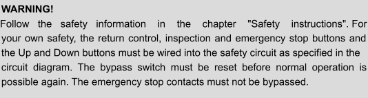

If the return switch is on, terminals 11 and (102) must be de-energised and terminal 101 must be live.
If the correction switches S71 and S72 are present, they must be installed at the end stop at the right deceleration point and must switch safely.
The contacts of the safety circuit must be closed Up or Down by pressing the emergence control mode key or must be bypassed through the return control On switch.
The travel commands are managed and controlled by the bp308 control system. If there is an existing safety light barrier, terminal X7.53 (door B: X7.56) must carry voltage. The command transmitter (return control) is located in the control cabinet, in the control cabinet door or on the external control unit.
The return control essentially works like the inspection control. However, the following safety devices are bypassed:
- Speed limiter,
- Buffer contacts,
- Emergency limit switch,
- Safety gear and
- Low pressure switch on hydraulic lifts.
The car can be moved out of the limit switches if the inspection control is switched off and the return control is switched on.
Switching on the return control deletes all calls and the command transmitters for car calls, landing calls and for higher-level control systems are switched off.
If the control system is not equipped with an absolute encoder, a correction run is necessary after it has been switched back to normal operation. For this, make a call.
-
First travel with inspection
The inspection control is used to move the lift for assembly and maintenance purposes.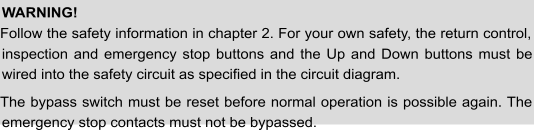

In case of activated inspection switch, terminals 11, (101) or (401) must be de- energised. The correction switches S71 and S72 must be installed at the end stop at the right deceleration point and must switch safely.
All contacts of the safety circuit must be closed when the Inspection »Up« or
»Down« buttons are pressed.
The travel commands are managed and controlled by the bp308 control system. All devices of the safety circuit remain effective. A contact interruption in the safety circuit leads to the immediate standstill of the lift. If there is an existing safety light barrier, the contact X97.53 (door B: X97.56) must carry voltage.
The inspection control is located on the roof of the car. By switching on the inspection control, automatic door movements are prevented and at the same time, the lift is locked for automatic operation. A movement of the car and the door drive is only possible when both buttons of the inspection control are pressed simultaneously (dead man’s control) and, in addition, the return control is switched off or not available. Additionally, by pressing an emergency braking switch, which only goes back to the starting position by means of rotary release, an emergency stop can be triggered. Overrunning the end stops is prevented by the limit switches.
Switching on the inspection control deletes all calls and the command transmitters for car calls, landing calls and for higher-level control systems are switched off. All devices of the safety circuit remain effective.
If the lift is switched back to normal operation, a correction run for the landing counter can be triggered after a call. For control systems with an absolute encoder, no correction run is necessary.
-
Inspection control Shaft pit
The inspection control in the shaft pit serves for testing and maintenance purposes. The return to normal operation of the lift may only take place after resetting the inspection switch to its normal position and must call for the intervention of a competent person responsible for the maintenance.
In addition, a return to normal operation effected in the shaft pit by the inspection control may only take place under the following conditions:
- Shaft doors, which allow access to the shaft pit, are closed and locked
- all emergency brake switches in the shaft pit are not actuated
- an electric reset device outside the shaft is actuated
The lift control system supports two different electrical reset devices:
- Reset by means of Key Switch
- Reset by means of landing call
-
Reset by means of key switch
The return to normal operation is carried out by operating the key switch “Reset Shaft Pit Inspection (805)” and in compliance with the above-mentioned conditions by the control system.
The reset by means of key switch is allowed for individual and group control systems.
-
Reset by means of landing call
The reset by means of the landing call is only applicable for individual control systems and not allowed for group control systems.
In the lift control system, at least one access of the lowest landing must be set, from which an electrical reset is accepted.
This setting can be made in the setup menu under
Features > Control system > Special functions > Floor/door for return to normal operation.
Figure 64:
Setting the access for leaving the shaft pit
When entering the shaft pit, it is mandatory to follow the steps below in the specified order:
- Open shaft door of the access to the shaft pit
- Actuate emergency brake switches in the shaft pit
- Enter shaft pit
- Close shaft door of the access to the shaft pit
- Activate Inspection mode Switch setting
- Switch off emergency brake switches in the shaft pit
When leaving the shaft pit, it is mandatory to follow the steps below in the specified order:
- Actuate emergency brake switches in the shaft pit
- Bring the inspection switch to the normal position
- Open shaft door of the access to the shaft pit
- Leave shaft pit
- Switch off emergency brake switches in the shaft pit
- Acknowledgment of the landing call starts to flash for a maximum of 30 seconds
- Close shaft door of the access to the shaft pit
- Activate the landing call in the phase in which the movement command acknowledgment is switched off
- Press landing call for at least 3 seconds and maximum 6 seconds
After valid operation of the landing call, the flashing acknowledgment disappears, and the doors are locked. The lift is available for normal operation.
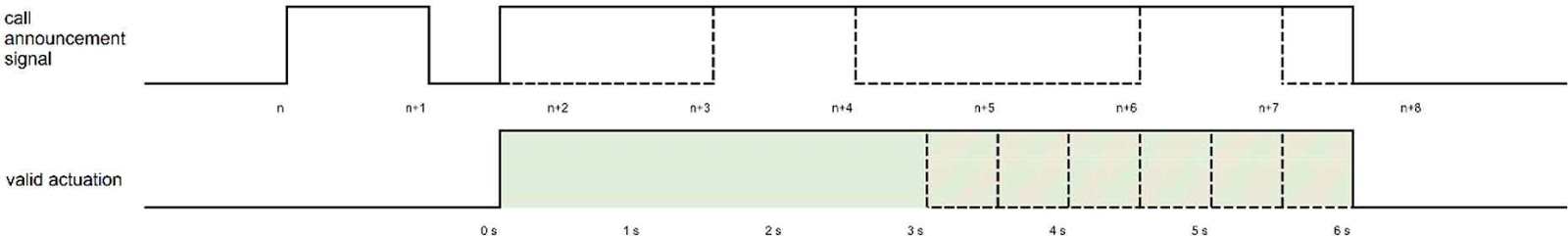
Figure 65:
Valid actuation of the landing call
If the required sequence has not been complied with or if a valid actuation of the landing call has not been carried out within 30 seconds, the lift is not available for normal operation. The required work steps can be repeated at any time in the specified order.
Alternatively, returning to the normal operation can be carried out by activating and deactivating the return control, the inspection control on the car, or unlocking on the lift control with multi-level security question.
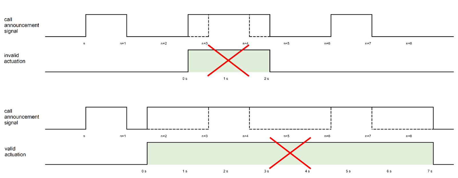
Figure 66:
Invalid actuation of the landing call button
The reset by means of the landing call button has been confirmed by an independent inspection body as conforming to the requirements of EN 81-20, 5.12.1.5.2.2. The certificate of the type examination certificate can be requested by Böhnke + Partner GmbH Steuerungssysteme.
-
Sequence of a regulated two-speed drive
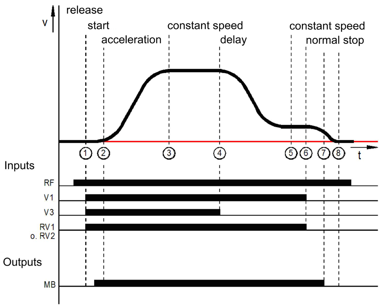
Figure 67:
Control system of an inverter with the RVM-01 in a normal drive
After switching on the main contactors and release of RF through the control system, the convertor receives the signal for start-up with the activation of the direction and speed V2. The inverter keeps the drive with speed n=0 at standstill and sends the signal MB to open the electromagnetic brake via terminal 31 to the control system (1 to 2). After switching on the brake via the relay on the control system, the drive accelerates until the specified speed is reached (2 to 3). Subsequently, a drive at constant speed (3 to 4) takes place until the activation of the speed V2=0 is stopped. The drive decelerates to the positioning speed V0 (4 to 5). After a short distance, the speed is no longer controlled (5 to 6), the drive continues to decelerate (6 to 7). When the drive has come to a standstill, the inverter applies the electromagnetic holding brake MB (7 to 8). The main contactors are switched off with the signal RF with a time delay.
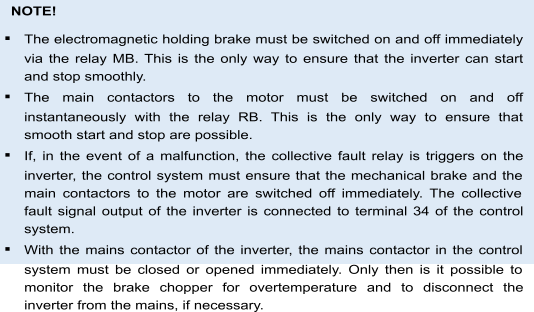
8.9.1 Disconnection points for the high travelling speed
The deceleration distance can be found in the diagram. The values indicated are only valid if the factory setting for the rounding remains unchanged. In addition, it is assumed that the control system forwards the disconnection points to the inverter immediately.
The values shown here are guidelines and should be adapted to personal on-site preferences.
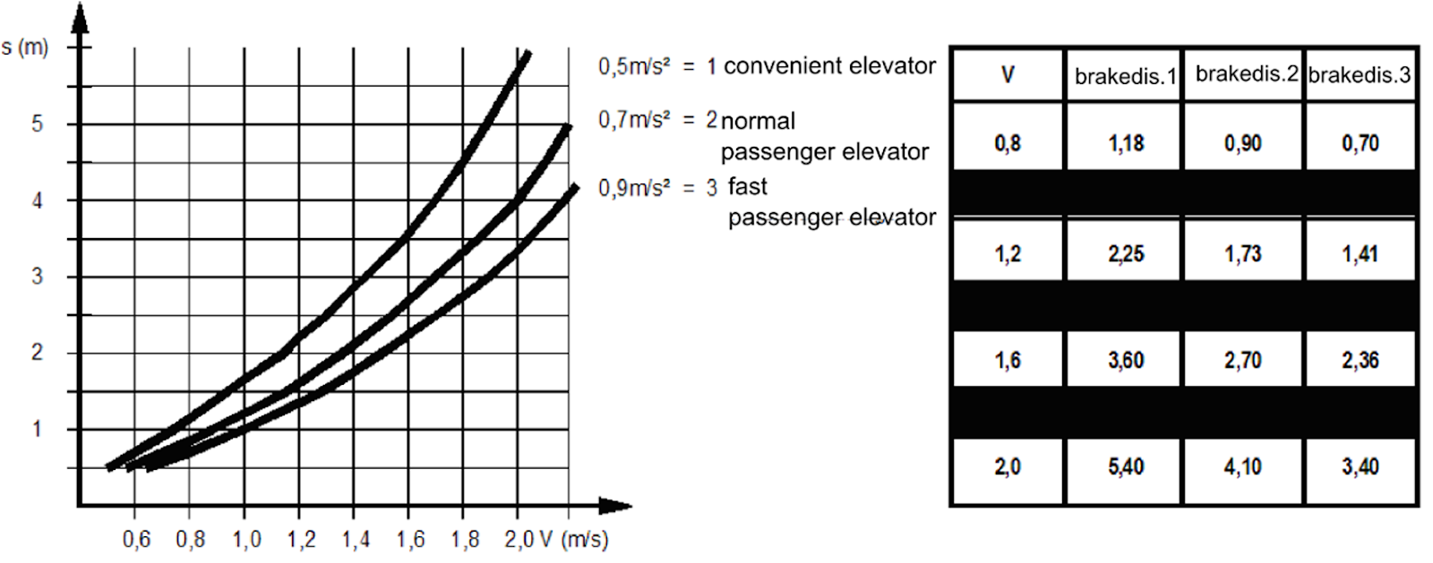
Figure 68:
Braking distance diagram and table
-
Sequence of a direct travel-in with DCP
In case of the DCP3 protocol, only the signals that occur via terminals when the inverter is controlled are exchanged serially between the control system and the inverter. The travel behaviour corresponds to a normal travel as described in the previous chapter.
In case of the DCP4 or CANopen Lift protocols, in addition to a few control signals, the remaining distance to the next landing is transferred cyclically from the control system to the inverter. This allows the inverter to calculate an ideal travel curve and to carry out a travel with direct travel-in into the stop.
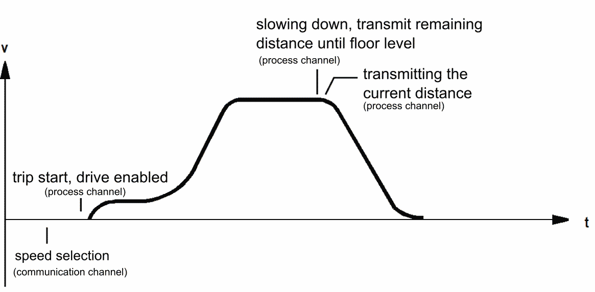
Figure 69:
Drive curve of a drive with direct drive-in
-
Setting up the copying tool
If driving with the inspection control is possible, the shaft copying encoders are installed and set up. These can be magnetic switches, absolute angle encoders (AWG-05) or contactless encoder systems such as the USP or laser positioning systems.
-
Installing the delay switch
Figure 70:
Impulse diagram of the delay switches
The deceleration in the end landings is initiated when the switches of the direction of travel correspondingly open. The delay switch S81 opens and decelerates for the upper end stop. The delay switch S82 opens and decelerates for the upper end stop. The speed of the inspection and return control must be switched off at these deceleration points. The levelling position of the end stop may not be overrun.
Make the following settings in the service menu:
- MAINTENANCE
- MAINTENANCE FUNCTIONS

Scroll down to the function in this category
- ACTIVATE ASSEMBLY DRIVE
and select ON. Now, continue to scroll to
- ASSEMBLY DRIVE WITH PRE-LIMIT SWITCHES
(S81/S82) and select ON.
Now you can perform the first travel via inspection/return to install the absolute encoder system as described in chapter 6.6.
Figure 71:
Activation of the assembly drive in order to be able to move the car without encoder system.

Figure 72:
Note regarding the activated assembly drive in the default image.
-
Basic settings
After installing the absolute encoder system (see attached installation description), the following default settings must be carried out on the bp308 in the setup menu:
Setup menu: > PARAMETERS
- LIFT DATA
- COPYING TOOL > ABSOLUTE ENCODER (CAN)
next: > PARAMETERS
- COPYING TOOL
- AWG1 PARAMETERS
- ENCODER SYSTEM
or
- USER-DEFINED
Deceleration points and levelling positions can be comfortably changed via setup menus.
In the service menu, the following basic settings must be carried out:
Service menu: > SETTING
- FUNCTIONS
- DRIVE
- DRIVE SPEED
- BRAKING DISTANCE
- MINIMUM DRIVE DISTANCES
Here, enter the nominal and intermediate speeds of the system.
Further in the menu:
- SETTING
- DISTANCE MEASUREMENT
- PARAMETERS
- GENERAL DISTANCES SHAFT PIT
SHAFT HEAD CAR HEIGHT
The approximate shaft pit depth must be specified. This is the distance between the threshold of the lowest landing and the shaft bottom. This value is set to 1 m by default and serves for receiving the image of the shaft as accurately as possible.
-
Setting travel with the absolute encoder
After these settings have been carried out, the setting travel can be begun, taking into consideration the following instructions. In the setting travel, the exact levelling positions of all landings are determined and stored in the programming memory.
Please proceed as follows:
- Switch the system to RETURN OPERATION.
- Using the return control, take the lift to the lowest stop (Landing 1) as close to the levelling position as possible. You can reach the exact levelling position with the cable elevator by releasing the brake and rotating the handwheel.
- In case of the hydraulic lift, you must set the levelling position by pressing the emergency release valve or the hand pump.
- If the lift stands levelled on landing 1, either press the >>OK<< key on the LC display or the car call key of Landing 1.
For checking purposes, the correct reading of the levelling position is signalled by 1 through the acknowledgement lamp.
- Proceed similarly for the remaining landings.
- Switch off the return operation.
- Subsequently, travel to every landing and check the levelling positions. Make a note of the deviations.
- Enter the corrections on the control system using the control panel.
- Once all levelling positions are checked and corrected, the normal operation can be switched back again.
Figure 73:
Setting ranges
Now, travel to every landing from both directions of travel and check whether the lift does a levelled travel-in. For this, use the levelling test under DIAGNOSIS > SHAFT SIGNALS > LEVELLING TEST.
If the lift does not stop at the previously set position, the
BRAKING DISTANCE V0 (STOPPING DISTANCE)
can be adjusted under FUNCTIONS > DRIVE.
The sensitivity of the readjustment range can be set independent of the levelling range. Refer to service menu:
TIMES > DRIVE / READJUST DECELERATION TIME
-
Travel speeds

Figure 74:
Levelling test
The travel speeds are set in the service menu in the menu option
SETTING> FUNCTIONS > DRIVE.
Abbreviation for the name of the speed:
VN = Readjusted speed VI = Inspection speed
VR = Return speed
V0 = Travel-in speed
V1..V7 Intermediate speeds and fast speed, depending on the set travel type.
In case of a change in the travel speeds, a calculation of the braking and minimum travel distances will be offered. These must be adjusted, if necessary.![]()
Figure 75:
Drive curve in the example of a DCP3 connection with V4 as nominal speed

Braking distance V1…7 = Deceleration distance to the landing Braking distance VI = Deceleration distance in case of inspection Braking distance VR = Deceleration distance in case of return
(If separately supported by the drive.)
Braking distance V0 = Disconnection point (Stopping distance)
Re-levelling downwards = Re-levelling to the landing Re-levelling upwards = Re-levelling to the landing
Lower levelling area = Levelling test during stoppage Upper levelling area = Levelling test during stoppage
Lower zone area = Starting point doors opening early to the
landing
Upper zone area = Starting point doors opening early to the landing
- Shaft pit (underpinning)
Default value is 1 m. This can be adjusted according to the actual value in order to measure the shaft with effective values. It also defines the valid application area of the encoder.
- Shaft head (Headroom)
Shaft pit is 1.5 m. This can be adjusted according to the actual value in order to measure the shaft with effective values. It also defines the valid application area of the encoder.
- Car height
This is required for the start-up of the maintenance position, which should be chosen such that the assembler can comfortably get on the car ceiling.
-
Deceleration through S81/S82 in the end stops in case of normal operation
Additional safety equipment for the end stops may be necessary due to the structural condition of the system. It should ensure that the lift is safely switched to the travel-in speed (V0) before reaching the end stops. This possibility offers the use of the delay switches S81 and S82.

The travel with the maximum speed must be decelerated at these deceleration points and may not overrun the levelling position of the end stop.
The deceleration is initiated when the switches of the direction of travel correspondingly open.
The delay switch S81 opens during the upward travel and always starts the slow speed (V0) before the upper end stop.
The delay switch S82 opens during the downward travel and always starts the slow speed (V0) before the lower end stop.
Setting in the setup menu: > FUNCTIONS
- COPYING TOOL
- PRE-LIMIT SWITCH (S81/82) ON
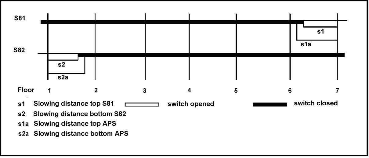
Figure 76:
Impulse diagram with magnetic switches and AWG-05
-
First travel in the normal operation


|
Have you followed all points of the previous checklists (see chapter 8.4 and 8.5)? |
Yes □ |
|
No current malfunctions are displayed on the LCD display of the bp308 and of the drive? |
Yes □ |
|
The return control and the inspection control are functional, as described in chapter 8.7 and 8.8. |
Yes □ |
|
The emergency limit switches are installed, configured and tested for functioning. |
Yes □ |
|
The safety switches are installed, configured and tested for functioning. |
Yes □ |
|
The detachable bumpers are installed and functional. |
Yes □ |
|
The required switching magnets in the shaft are installed according to the impulse diagram. |
Yes □ |
|
The correction switches are installed, configured and tested for functioning according to the deceleration distance. |
Yes □ |
|
The setting travel with the absolute encoder AWG-05 is carried out as described. (chapter 8.12.3) |
Yes □ |
|
The setting travel with the drive is carried out as described by the manufacturer. |
Yes □ |
|
If there is a DCP connection to the inverter, the setting travel with the DCP parameters is carried out as described. (chapter 8.6.4) |
Yes □ |
|
The brake application points are set such that a proper deceleration is possible until standstill. |
Yes □ |
|
The car door blade passes through the outer door rollers at a sufficient clearance. |
Yes □ |
If you have answered all questions with »Yes«, then you can proceed as follows.
|
Keep the doors closed, see maintenance menu. Switch off the landing control. |
Yes □ |
|
Before the first start, place the car levelled in the upper or lower stop with the inspection or return control. |
Yes □ |
|
After switching back to normal operation (inspection and return control off), the LC display shows the status for the lower or upper stop. |
Yes □ |
|
Now start the lift from the machine room, with the »Up« or »Down« buttons to control the free travel through the shaft. |
Yes □ |
|
In the menu DIAGNOSIS > SHAFT SIGNALS, you can control the incoming impulses for the shaft copying. |
Yes □ |
|
In the menu DIAGNOSIS > SIGNALS, you can control the input and output signals. |
Yes □ |
|
After the first travel, you can control the levelling position, the brake application points and, in the case of regulated lift systems, the control parameters and optimise them as required. |
Yes □ |
|
Now check the course of the travel via the car control panel at all upward and downward stops. |
Yes □ |
|
Switch on the landing control and now monitor the course of the travel via the landing units at all stops upwards and downwards. |
Yes □ |
|
Check the landing indicator, out of operation indicator, direction indicator |
Yes □ |
|
Check light barrier, clamping force limiter, emergency alarm, etc. |
Yes □ |
You can now continue with the optimisation of the travel behaviour.
-
Setting up the emergency call device
According to EN 81-28, every lift must be equipped with an emergency call device at a permanently manned location. After wiring the emergency call device, set up the emergency call device according to the attached description. The function of the emergency call system must be verified through test emergency calls.
-
Setting up the group connection
If it is a lift group and all lifts are running correctly as individual control systems, then establish the group connection with the pluggable cross connections. Check the correct setting of the group parameters and, in case of an activated landing control, pay attention to incoming landing calls in parallel for all group participants.
Switch off the landing control for all group participants. Landing calls may now no longer be accepted. Switch on the landing control one by one for only one group participant at a time and check the function of the landing calls.
-
Setting up the remote diagnosis
The remote diagnosis can be done via different networks. If the wiring is done according to the available circuit diagrams, you can set up the connection.
Please note that you can shut down the lift on site or via remote data transmission (DFÜ) unintentionally by entering incorrect parameters (e.g. runtime monitoring set too low). If switching devices for the parallel operation of a modem and an emergency call device are used on a common telephone connection, these must be approved by Böhnke + Partner GmbH.
The options provided by WinMOS®300 with regard to the lift attendant function do not relieve the user of the obligation to ensure, for any system on site, that the safety equipment (e.g. emergency stop and emergency call) is not put out of operation by any wilful damage.
A software update of the control system or components necessary for the function of the lift may only be carried out if it is checked on site by qualified personnel.
-
Setting up the modem
If an analogue modem, which must correspond to the V 250 standard, is used for remote diagnostics, the parameters for the communication can be entered after the wiring has been completed. These include, in particular, the interface used, the DFÜ300 protocol, the telephone numbers to be called in case of malfunctions and emergencies. Furthermore, you should set when a callback to the control centre should be made, for every malfunction, only in case of lock, or never.
-
Setting up a networkconnection
If the remote diagnosis is carried out via a network connection, the following parameters must be entered:
- IP address: e.g. 192.168.0.119
- Subnet mask: e.g. 255.255.255.0
- Gateway: e.g. 192.168.0.2
- Port: e.g. 8000 (default setting)
-
Completion of commissioning
After completion of the commissioning, it is advisable to store the current parameterisation of the system in the documents. To do this, read the parameters with WinMOS®300 from the system and attach the printout to the documents. If WinMOS®300 is not available for you, note down the settings in the attached printout of the setup and service menu.
The malfunctions stored in the stack memory and the malfunction list during commissioning as well as the entries in the maintenance stack can be deleted.
If access by third parties (such as janitors) is possible, you should protect access to the menus by assigning a setup and service code.
Due to the digital structure of the control systems, many possible error causes are already displayed in plain text. Generally, the cause can be found based on these messages/malfunctions in the Malfunction stack memory. If the system is locked due to a malfunction, the backlight of the LC display flashes and the abbreviation
»SPE« for lock is displayed. To determine the exact cause of the malfunction, please

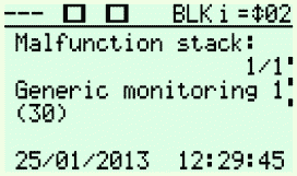
Figure 78:
Representation of an entry in the stack memory with lock.
look at the stack memory. If the cause of the malfunction has been removed, the lock can be activated by pressing the »Call/End« button and responding to the instruction with the »OK« button or by momentarily switching off the operating voltage.
-
Monitoring routines
The software in the bp308 monitors a variety of signals for level and time behaviour. If an irregularity occurs, a corresponding error message is stored with a timestamp in plain text in the malfunction stack. The malfunction list displays how many times an error has occurred.
If a stipulated control or monitoring time (e.g. start time control, travel time monitoring, travel delay control) is exceeded, the lift drive is switched off and all travel commands are deleted. If warning devices are activated, the lift is stopped at the next stop and a restart is prevented. The warning devices include engine overload switches, pressure switches and temperature switches for the hydraulic system.
If the safety circuit is activated, the travel is aborted, and all travel commands are deleted.
The activation of the of the door-locking control also leads to the deletion of the travel commands. The door-locking control gets activated after three door-locking attempts.
The levelling position of the car is monitored by the absolute encoder or by level switches. If the levelling position is exited when the lift is stationary, a readjustment will take place. The readjustment with open doors is possible because the door and bolt contacts within the door zone area are bypassed by the safety circuit accordingly.
- PTC resistor
Terminals PTC / PTC, all current PTC resistors are monitored.
- Travel time
The start, fast and slow travel phases are monitored. See menu »Control times«.
- Contactor dropout (33)
The travel contactors are checked for dropout before the start.
- Brake released (35)
The release of the brake shoes is checked by contacts before the start.
- Door and bolt control
The closing of the safety circuit is monitored before the start. See menu
»Control times«.
- Safety circuit
The input and output signal of the integrated safety circuit is monitored.
- Regulations / LRV (34)
The malfunction output of the inverter is monitored.
- Open/close brake (31)
The »mechanical brake« output of the inverter is monitored.
- Impulses / level / correction (71-78)
The signals from the shaft are checked for plausibility if no AWG is used.
- Re-levelling (without AWG: 73-74 / 77-78)
The monitoring takes place 20 times and 20 seconds per direction and landing.
- Safety circuit (Terminals SSZ, 9, 10, 11, 12, 12A, 12B, 13, 14)
The monitoring is carried out during standstill and during the travel.
- Correction signals /absolute encoder
The signals from the shaft are checked for plausibility.
- Lock
Observations can be parameterised with a lock.
-
Malfunction information
Disturbances influence the sequence of functions in the lift control system in such a way that proper operation is not possible. All current events that have led to a malfunction of the lift functions are displayed, e.g.
- Speed limiter has been activated
- PTC resistor in the drive motor, PTC resistor in the hydraulic unit,
- start control, travel control, deceleration control,
- brake control, contactor control,
- copying error,
- inverter malfunction,
- door-locking/opening control,
- Safety circuit.
If a malfunction occurs, it is recorded in the malfunction stack and the malfunction list. If the system is connected to a WinMOS®300remote diagnostics system, a callback can be triggered when a malfunction occurs. All malfunction information can also be transmitted with Lift2CLOUD.
Critical errors can lead to a locking of the system. The lock can be aborted after the cause has been eliminated. The abortion can be activated by pressing the
»Call/End« button and responding to the instruction with the »OK« button or by momentarily switching off the operating voltage.
Very serious malfunctions cannot be reset by switching off the operating voltage. Non-serious errors such as door-locking errors can be reset via a new call.
-
Reporting of malfunctions
All bp308 are prepared for the remote diagnosis. To connect the control system to an intranet or the Internet, the bp308 control system is equipped with a LAN connection. If the connection is made via the telephone network, a modem can be connected to the USB-A interface. Gateways for the LONmark standard, OPC server, Profibus, Modbus and BACnet are available for the connection to the building automation.
If the malfunction recall is activated in the setup menu, it will be transmitted along with the type, date and time to the set service centre after a malfunction has occurred.
More detailed information on the remote diagnosis can be found in the WinOS®300 manual or under www.WinMOS.de.
-
Malfunction stack
The last 128 malfunctions are stored with the timestamp in the malfunction stack. The malfunctions are stored in chronological order. A display routine makes it possible to display the malfunction messages on the LC display in plain text. The following is displayed:
- the date,
- the time,
- the malfunction,

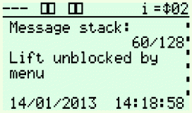
Figure 78:
Representation of an entry in the malfunction stack memory.
- and in case of landing-based malfunctions, even the landing and the registered landing designation.
The “Right” key can be used to open a malfunction entry. The position, speed and a selection of important signals, which were present at the moment of the event, will then become visible.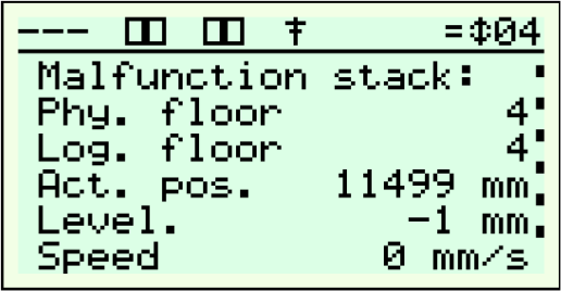
It is thus possible to understand a history of
the malfunctions that have occurred most recently.
To delete the stack, press the »OK« key and
Figure 79:
Additional details of an entry in the malfunction stack memory.
also respond to the security query with the »OK« key. For complete logging, we recommend deleting the malfunction stack only after the entries have been transmitted to a WinMOS®300control centre or to the cloud.
-
Malfunction list
The number of all registered malfunctions is stored in the malfunction list. The following is displayed:
- the malfunction,
- the frequency,
- and in case of landing-based malfunctions, even the landing.
A display routine makes it possible to read the malfunction list on the LC display in plain text.
To delete the list, press the »OK« key and respond to the security query with the
»OK« key. For complete logging, we recommend deleting the malfunction list only after the entries have been transmitted to a WinMOS®300control centre or to the cloud.
-
Messages
Messages indicate special states of the system and that the operation of the lift is currently only possible to a limited extent. All information that has led to a message at that point is displayed.
Examples:
- Landing control is switched off.
- Emergency stop actuated in the car
- Inspection switched on
- Return control switched on.
- Internal draw unit is switched on.
- Priority calls are available.
- Full load or overload contact has been activated.
- Fire evacuation travel/fire brigade travel is switched on.
- Backup power supply active
- Lift from the group
- Car travels to the parking landing.
- Car is on the parking landing.
-
Repair
If is a malfunction in the control electronics is verifiable, it is not recommended to carry out an on-site repair for economic reasons.
In order to save costs and time in case of questions, you should have the controlling number and circuit diagrams ready when you call us.
Before beginning a maintenance, we recommend registering this on bp308 in the service menu under
MAINTENANCE > MAINTENANCE FUNCTIONS > MAINTENANCE ON
This means that malfunction information is no longer sent via remote data transmission and the system is visualised as “In Maintenance”.
As part of the usual maintenance work, the following checks must be carried out on the control systems bp308:
- General visual inspection for possible dust deposits, moisture or corrosion. If they are present, they must be removed.
- Are the connections of the control system mounted correctly?
- Do the malfunction memory stack and/or the malfunction list display errors? Check registered malfunction messages and, where appropriate, delete them.

- Check messages and the message stack (recorded messages) for anomalies.
- For the emergency lighting unit, it must be ensured that the capacity of the battery is sufficient for one hour of emergency lighting in the car.
- During the use of uninterruptible power supply systems (UPSs), the maintenance instructions in the attached manuals must be complied with.
Figure 81:
Entry in the malfunction stack memory

Figure 82:
Entry in the message stack memory
- The toothed belts of an absolute encoder system are maintenance-free under normal conditions.
![]()

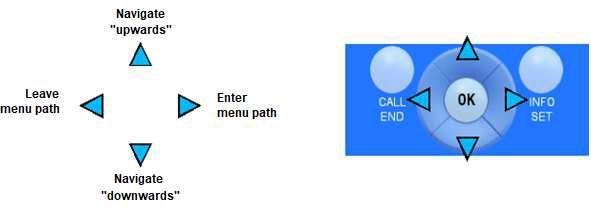
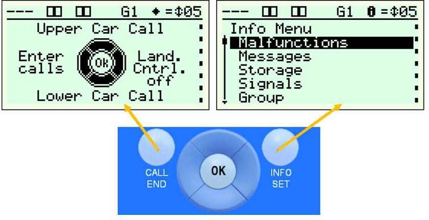
![]()
- Update of the firmware via USB stick

- To access the monitor program where you can save and update the operating software, press and hold the two outermost keys for about 3 seconds
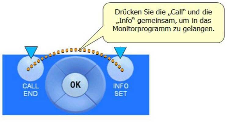
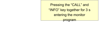
A
Absolute encoder 65
Absolute encoder copying 96
Absolute encoder fastening sets 65
Acceptance test 89
Aggressive mediums 62
Ambient temperature 59, 61
Application profile CiA 417 36, 75, 83
Application profile for lifts 81
Assembly 12, 61
Assembly instructions 65
Attenuation filter 91
B
Basic settings 111
Battery 51, 52
Baud rate 75
Bridges 75, 80
Brief description of bp308 40
Building automation 121
Bus lines 68, 75, 83
Bus topology 78, 79, 80
C
Cable colours 75
Cable routing 76
Cable shield 72
Cable shields 72
Call menu 48
CAN network 51
CAN parameters 101
CAN-Bus 36, 49, 75, 76, 83, 86, 100
CANopen 33
CANopen Lift interface 83
CANopen lift standard 81
CAN-Wireless-Interface CWI-01 39
CANwizard® 101
Car 64, 65, 69, 77
Car electronics CLK-03 39
Car terminal box 64, 82
Checking the bus lines 100
Checking the parameters 99
Checking the termination 100
Checklist before switching on 97
Commissioning 9, 89
Components 33, 36, 39, 62, 82, 86
Condensation on all components 62
Connecting the mains voltage 99
Connection of absolute encoder (AWG) 86
Connector pin assignments 81
Control cabinet 55
Control circuit 69, 90
Control panel and LCD 44
Control system bp308 33, 36, 39
Cooling air 61
Correction switch 92, 102, 103, 116
D
Danger to persons 61
Data connections 69
Data lines 62, 69, 86, 87
Data transmission 87
DCP 35, 83, 101, 109
Deceleration point 102, 103, 114
Decentralised lift control system 36
Declaration of conformity 13
Delay switch 110
Delivery status 62, 68
Demand-oriented maintenance 34
Disconnection point 108, 114
Disposal 52, 59
D-Sub 9-pin 81
E
EEPROM 51
Electrical bus medium 75
Electrical connection 67
Electrical installation 74
EMC Directive 31
EMC instructions 31
Emergence control mode 92, 93, 102, 110
Emergency call manager 87, 88
Emergency call system 88, 102, 103
Emergency control 95
Emergency limit switch 73, 94, 95, 102, 115
EN 81 14, 32, 68, 69, 90, 92, 106, 117
End stops 114
Ethernet 33, 43, 51, 62, 87
EU Type Examination 14
EU Type-examination certificate 15
Excess current release 91
Excess pressure switch 95
128 Installation manual of system “bp308” – Index
F
Failure of a phase 32, 96
First travel in the normal operation 115
First travel with inspection 103
First travel with the return control 102
Flat travelling line 82
free travelling cable cores 69
Frequency inverter 34, 49, 55, 82
G
Gateway 118
Ground connections 69
Ground rail 69
Grounding point 69
Group connection 78, 79, 80, 86, 117
Group of lifts 36
Group participants 86
Guide rail 65
H
Humidity 58, 61
I
Impulse diagram 92
Information menu 49
Inspection control 103
Inspection control Shaft pit 104
Inspection drive 92
Inspection keys 112
Inspection speed 113
Installation and assembly 61
Installing the delay switch 110
Insulation measurement 91
Interfaces 33
Interference impulses 31, 68
Interference suppression measures 68
Intranet 87
IP address 118
K
Keys 45
L
Labelling in circuit diagrams 72
Landing control 48, 93, 94, 116, 117, 123
Landing panel board CAP-02 39
LC-Display 44
Level switch 92, 93, 119
Lightening protection measures 68
Line structure 76, 77, 78, 79, 80
Load connections 69
Load lines 62, 68, 69
Locking of the system 121
LONworks- standard 33
LPCmon 50, 53
M
Magnetic switch 65
Magnetic switch copying 95
Mains filter 69
Maintenance 125
Malfunction list 122
Malfunction memory stack 35, 89, 125
Malfunction stack 122
Malfunction stack memory 119
Messages 123
Modem 87
Monitor program 50
Monitor program LPCmon 50
Monitoring routines 119
Motor protection 93
Mounting plates 69
N
Network 118
Network topology 76
Notification of arrival 9
Notification of departure 9
O
Open-Style plug 81
Operating conditions 61
P
Parameter 45, 46, 47
Parameter memory 51
Parking landing 51, 93, 123
Preparations 90
Primary voltage 62
Printed circuit boards 31
Programming memory 51, 112
Protective equipment 61
PTC thermistor monitoring 34, 93
Q
Qualified personnel 9
R
RC combination 69
Installation manual of system “bp308” – 129
RCD circuit breakers 62, 91, 98
Readjusted speed 113
Readjustment 96, 119
Real-time clock 34, 51
Regulations 56
Re-levelling 14, 32, 35, 56, 114, 120
Remote data transmission 51
Remote diagnosis connection 88
Remote diagnosis of data 33
Remote diagnosis system 88, 121
Repair 123
Repeater 75
Reset by means of key switch 104
Reset by means of landing call 104
Residual current-protective circuits 62
Return control 102
Return speed 113
Risk of injury 7
RJ45 81
Rolling noise 65
Runtime control 94, 96
Runtime monitoring 95, 96, 117
S
Safety circuit 14, 33, 34, 40,
……………………………………..56, 73, 119, 120, 121
Safety circuit monitoring 33
Safety equipment 114
Safety instructions 9
Service code 47
Service menu 47, 111
Setting up a network connection 118
Setting up the copying tool 109
Setting up the emergency call device 117
Setting up the group connection 117
Setting up the modem 118
Setting up the remote diagnosis 117
Setup menu 46, 111, 115
Shaft head 65, 86, 114
Shaft pit 65, 104, 105, 114
Shaft signals 86, 92
Shafting correction system 94, 96
Short circuit measurement 91
Shut-down points 92
Signal lines 83
Software update 53
Sound insulation 55, 62
Speed limiter 65
Standard control cabinet 34
Standards 31
Start of the monitor program 50
Storage, transport and operating conditions 61
Subsidence correction system 94
Switching agreements 11
System module bp308 14, 63
T
TCP/IP 118
Technical information 90
Telephone connection 87, 88, 117
Terminal mode 49
Termination 75, 77, 78, 79, 80, 83, 86, 100
Toothed belt 65
Topology 77
Trailing cable 64
Transmission lines 75
Travel speeds 113
Troubleshooting 119
Two-part group 78, 79, 80
U
Uninterruptible Power Supply 58
UPS 58
USB device 51
USB host 33, 51
USB laptop connection 33
USB stick 43, 53
USB-A port 87
V
Ventilation openings 61
Versions of bp308 40
Vibrations 61
Voltage fluctuations 69
W
Warnings 9, 61, 67
WinMOS®300 3, 33, 34, 35, 37,
………………………………….. 43, 117, 118, 121, 122
WinMOS®300 Control centre 122
![]()
130 Installation manual of system “bp308” –
SCHMERSAL BOHNKE PARTNER bp308 Installation Manual – SCHMERSAL BOHNKE PARTNER bp308 Installation Manual –
[xyz-ips snippet=”download-snippet”]