![]()
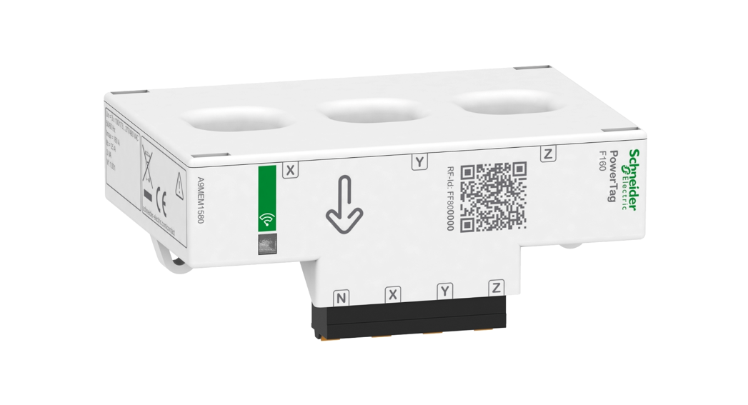
PowerLogicTM – PowerTag F160 3P/3P+N – A9MEM1580
Wireless Communication Energy Sensor
![]() Refer to the concentrator’s user manual to configure your system.
Refer to the concentrator’s user manual to configure your system.
 www.se.com www.se.com |
This instruction sheet must be kept for future use.
PLEASE NOTE
- Electrical equipment should be installed, operated, serviced, and maintained only by qualified personnel.
- PowerTap devices must not be repaired.
- PowerTap devices should not be installed if, while unpacking, any damage is observed.
- The PowerTap devices must be installed inside electrical panels or switchboards, behind a door or plate, so that they are inaccessible to unauthorized persons.
- The electric panels must meet the requirements of the applicable standards (IEC 61439-1) and be installed in compliance with current installation and safety rules (IEC 61140).
- All relevant local, regional, and national regulations must be respected while installing and using PowerTap devices.
- No responsibility is assumed by Schneider Electric for any consequences arising out of the use of this material.
![]() DANGER
DANGER
HAZARD OF ELECTRIC SHOCK, EXPLOSION, OR ARC FLASH
- Apply appropriate personal protective equipment (PPE) and follow safe electrical work practices. See NFPA 70E, CSA Z462 or local equivalent.
- This equipment must only be installed and serviced by qualified electrical personnel.
- Turn off all power supplying this equipment before working on or inside the equipment.
- Always use a properly rated voltage sensing device to confirm power is off.
- Do not use a PowerTap device for voltage testing purposes. A Voltage Tester must be used instead.
- Replace all devices, doors, and covers before turning on power to this equipment.
Failure to follow these instructions will result in death or serious injury.
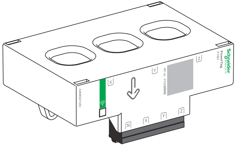
Description
1.1 PowerTap
 |
 |
|
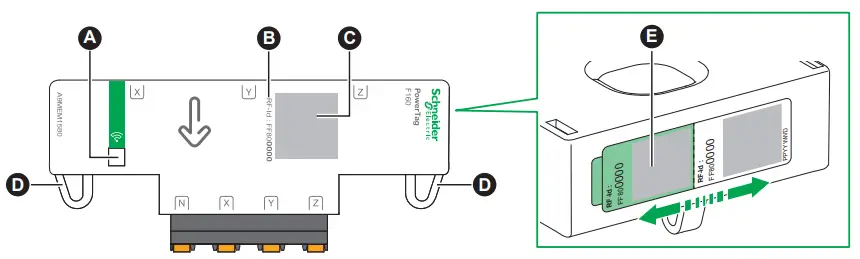
A |
Status LED. |
|
B |
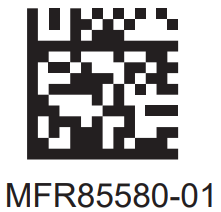
QR code to access device information. |
|
C |
RF-Id identifier. |
|
D |
Cable tie brackets. |
|
E |
Label with a detachable adhesive part carrying a QR code and a RF-Id identifier, useable during commissioning on certain concentrators. |
|
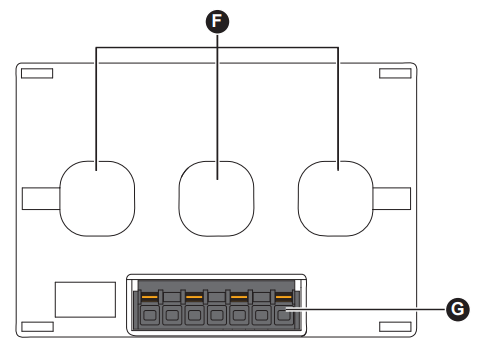
F |
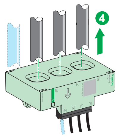
Conductor feedth roughs for current measurement. |
|
G |
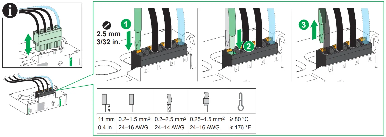
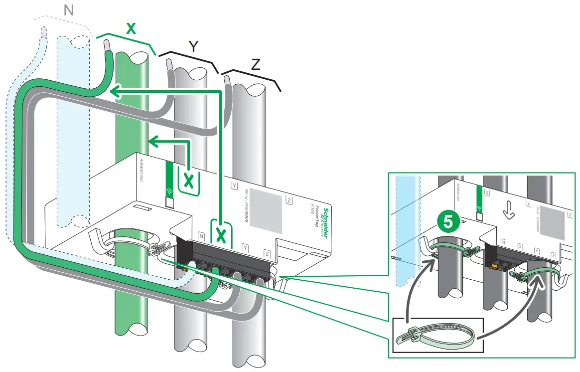
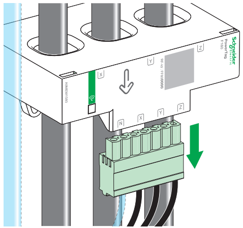
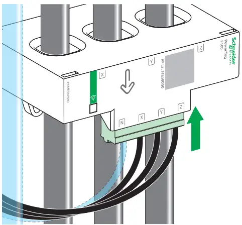
Withdrawable connector for voltage take-offs connection. |
1.2 Status LEDBefore proceeding with pairing, ensure that the concentrator has the latest available software version.Refer to the user manual of the concerned concentrator.
| → | Power Tag switched off. |
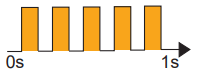 |
PowerTap is searching for a concentrator. |
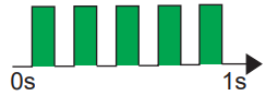 |
PowerTap in identification mode |
 |
PowerTap is in-network.Normal communication with the concentrator. |
 |
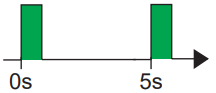
Occasional loss of communication. |
 |
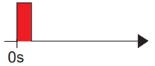
Loss of communication with the concentrator. |
 |
internal error detected. |
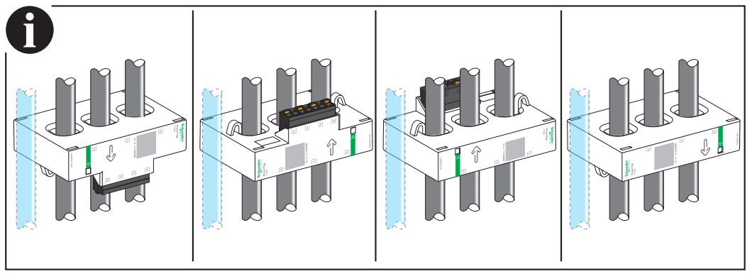
Installation and Connection
![]() WARNING
WARNING
FIRE HAZARDThe PowerTap must be associated with an easily accessible upstream protection (2 A) and circuit-breaker system, marked with callout in the schematic below.Failure to follow these instructions can A result in death, serious injury, or equipment damage.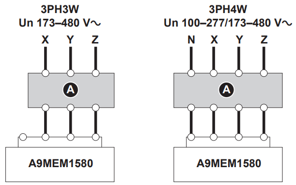
PLEASE NOTEInstall the PowerTap such that there is no mechanical interference between the voltage take-offs and the cover.
 |
 |
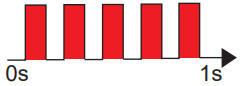
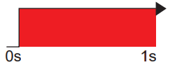
Dielectric Test
NOTICERISK OF DAMAGE TO POWERTAG
- Disconnect the voltage take-offs of the PowerTap before performing the dielectric withstand test or insulation measurements.
- Connect the voltage take-offs of the PowerTap after the dielectric test.Failure to follow these instructions can result in equipment damage.
 |
 |
| Dielectric test authorized. | After the dielectric test. |
Technical Data
PMD-II/DD/K70/1 – IEC 61557-12 – IEC 61010-1 – IEC 61326-1 (industrial electromagnetic environment)Imax: 160 A, Ib: 25 A
- Voltage range Un :3Na 100–277/173–480 V +/-20%
- Frequency: 50/60 Hz
- Maximum power consumption: y 3 VA
- Operating temperature:-25°C to +70°C (-13°F to +158°F)
- Altitude: y 2000 m (y 6500 ft)
- Relative humidity: Maximum 93%without condensation
- Impact resistance index: IK05
- Protection degree: IP20
- Overvoltage and measurement category: IV
- Withstands temporary surges on the power supply
- Pollution degree: 3
Symbols Printed on the Device
Description
| ∼ | Alternating current |
| Comply with all safety instructions associated with this symbol to avoid any potential risk of injury or death. | |
 |
WEEE directive 2012/19/EU (Waste Electrical and Electronic Equipment). |
Radio Frequency Compliance Statements
Europe
EU Declaration of ConformityHereby, Schneider Electric Industries SAS, declares that the energy sensor PowerTag is in compliance with the essential requirements and other relevant provisions of RED Directive 2014/53/EU.The EU FD19072901 declaration of conformity can be downloaded on www.se.com/docs.
- IEEE 802.15.4 operating frequency: 2405–2480 MHz.
- Maximum radio-frequency power transmitted: < 10 mW.
USA
Federal Communication Commission Interference StatementThis device complies with Part 15 of the FCC Rules. Operation is subject to the following two conditions:(1) This device may not cause harmful interference, and (2) this device must accept any interference received, including interference that may cause undesired operation.This equipment has been tested and found to comply with the limits for a Class B digital device, pursuant to Part 15 of the FCC Rules. These limits are designed to provide reasonable protection against harmful interference in a residential installation.This equipment generates, uses, and can radiate radio frequency energy and, if not installed and used in accordance with the instructions, may cause harmful interference to radio communications. However, there is no guarantee that interference will not occur in a particular installation.If this equipment does cause harmful interference to radio or television reception, which can be determined by turning the equipment off and on, the user is encouraged to try to correct the interference by one of the following measures:
- Reorient or relocate the receiving antenna.
- Increase the separation between the equipment and receiver.
- Connect the equipment into an outlet on a circuit different from that to which the receiver is connected.
- Consult the dealer or an experienced radio/TV technician for help.
FCC Caution: Any changes or modifications not expressly approved by the party responsible for compliance could void the user’s authority to operate this equipment.This transmitter must not be co-located or operating in conjunction with any other antenna or transmitter.Radiation Exposure StatementThis equipment complies with FCC radiation exposure limits set forth for an uncontrolled environment.This equipment should be installed and operated with a minimum distance of 20 cm between the radiator & your body.
Canada
Industry Canada StatementThis device complies with RSS-247 of the Industry Canada Rules. Operation is subject to the following two conditions:(1) This device may not cause harmful interference, and (2) this device must accept any interference received, including interference that may cause undesired operation.
Radiation Exposure StatementThis equipment complies with IC radiation exposure limits set forth for an uncontrolled environment.This equipment should be installed and operated with a minimum distance of 20 cm between the radiator & your body.
Schneider Electric Industries SAS 35, rue Joseph MonierCS3032392500 Rueil-MalmaisonFrancehttps://www.se.comMFR85580-01 Printed on recycled paper.
https://download.schneider-electric.com/files?p_Doc_Ref=MFR85580
 |
 |
© 2020 Schneider Electric – All rights reserved.
References
[xyz-ips snippet=”download-snippet”]