ATS480 Altivar Soft Starter
Altivar Soft Starter ATS480User ManualNNZ85515.02 07/2022www.se.com
Legal InformationThe Schneider Electric brand and any trademarks of Schneider Electric SE and its subsidiaries referred to in this guide are the property of Schneider Electric SE or its subsidiaries. All other brands may be trademarks of their respective owners.This guide and its content are protected under applicable copyright laws and furnished for informational use only. No part of this guide may be reproduced or transmitted in any form or by any means (electronic, mechanical, photocopying, recording, or otherwise), for any purpose, without the prior written permission of Schneider Electric.Schneider Electric does not grant any right or license for commercial use of the guide or its content, except for a non-exclusive and personal license to consult it on an “as is” basis. Schneider Electric products and equipment should be installed, operated, serviced, and maintained only by qualified personnel.As standards, specifications, and designs change from time to time, information contained in this guide may be subject to change without notice.To the extent permitted by applicable law, no responsibility or liability is assumed by Schneider Electric and its subsidiaries for any errors or omissions in the informational content of this material or consequences arising out of or resulting from the use of the information contained herein.
Table of Contents
NNZ85515.02 07/2022
Safety Information……………………………………………………………………………7Qualification of Personnel …………………………………………………………………8 Intended Use………………………………………………………………………………….8 Product related information ……………………………………………………………….8About the Book………………………………………………………………………………13Document scope …………………………………………………………………………..13 Validity note …………………………………………………………………………………13 Related Documents ……………………………………………………………………….14 Electronic product data sheet …………………………………………………………..15 Terminology …………………………………………………………………………………15 Software Enhancements …………………………………………………………………16 Contact us …………………………………………………………………………………..16Soft Starter Overview …………………………………………………………………….17 Inspect, Store and Handle the Product…………………………………………..19Inspecting the Product ……………………………………………………………………19 Storage and Shipping …………………………………………………………………….19Installation ……………………………………………………………………………………..21Unpacking and Handling …………………………………………………………………21 Weight And Lifting Lugs Availability ………………………………………………21 Unpacking and Hoisting the References on Pallet…………………………….21Soft Starter Mounting ……………………………………………………………………..22 Before you Begin ……………………………………………………………………..22 Mounting in an Enclosure …………………………………………………………..23 Mounting Position …………………………………………………………………….24Soft Starter Cooling and Power Dissipation………………………………………….25 Dimensions ………………………………………………………………………………….26 Installing Door Mounting Kit……………………………………………………………..30 Protective Covers For ATS480C41Y…M12Y ………………………………………..31 Fieldbus Modules ………………………………………………………………………….33Wiring……………………………………………………………………………………………. 34Power Terminals……………………………………………………………………………36 Power Connections ATS480D17Y…ATS480C11Y…………………………….36 Power Connections ATS480C14Y…ATS480M12Y ……………………………38 Connection Of The Motor and Supply Mains …………………………………..41Control Terminals ………………………………………………………………………….43 Control Terminals Layout ……………………………………………………………43 Control Block Wiring Diagram ……………………………………………………..44 Control Terminal Characteristics…………………………………………………..45 RUN and STOP Management……………………………………………………..46 Relay Contacts Wiring……………………………………………………………….48Application Diagrams ……………………………………………………………………..51 Upstream Protection Devices …………………………………………………………..59Checking Installation ……………………………………………………………………..60 Cybersecurity………………………………………………………………………………… 62Overview …………………………………………………………………………………….62 Security Policy…………………………………………………………………………65 Product Defense-in-Depth ………………………………………………………….663
ATS480 Security Policy ……………………………………………………………..69 Potential Risks and Compensating Controls……………………………………71 Data Flow Restriction ………………………………………………………………..72 Initial Setup ………………………………………………………………………………….72 Password……………………………………………………………………………………. 72 Security Event Logging …………………………………………………………………..73 Upgrades Management…………………………………………………………………..74 Clear Device / Secure Decommissioning …………………………………………….75Commissioning……………………………………………………………………………… 76Tools to Configure the Soft Starter……………………………………………………..77 Product HMI …………………………………………………………………………………78Description of the Display Terminals ……………………………………………..78 Front Product LEDs…………………………………………………………………..82 Soft Starter State …………………………………………………………………………..83 Initial Setup ………………………………………………………………………………….84 Structure of the Parameter Table ………………………………………………………90 Finding a Parameter in This Document……………………………………………….91 Main Menu Presentation …………………………………………………………………92 [Simply Start] SYS ………………………………………………………………………..93 Set The Currents ……………………………………………………………………..94 Set The Mains Voltage ………………………………………………………………96 Set Start Profile ……………………………………………………………………….97 Set Stop Profile………………………………………………………………………..98 Example Of Typical Configurations For Common Applications………….. 101 Small Motor Test…………………………………………………………………………. 102 Connection Inside The Delta Of The Motor ……………………………………….. 104 Diagnostic Of The Delta Connection ……………………………………………….. 105 Motor Preheating………………………………………………………………………… 108 Torque / Voltage Control……………………………………………………………….. 113 Voltage Boost…………………………………………………………………………….. 114 Second Motor Parameters…………………………………………………………….. 115 Cascade Motors …………………………………………………………………………. 123 Smoke Extraction ……………………………………………………………………….. 125 Factory Settings …………………………………………………………………………. 127HMI navigation ……………………………………………………………………………. 1281 [Simply Start] SYS …………………………………………………………………… 128 2 [Monitoring] PROT …………………………………………………………………… 1292.2 [Process underload] ULD ………………………………………………….. 136 2.4 [Process overload] OLD ……………………………………………………. 138 2.11 [Thermal monitoring] TPP ……………………………………………….. 139 3 [Complete settings] CST…………………………………………………………… 143 3.1 [Motor parameters] MPA ……………………………………………………. 144 3.2 [Mains contactor command] LLC ……………………………………….. 146 3.3 [Motor wiring] MWMT …………………………………………………………. 148 3.4 [Preheating] PRF ……………………………………………………………… 150 3.5 [Start & Stop] SSP ……………………………………………………………. 152 3.6 [Cascade] CSC ………………………………………………………………… 161 3.7 [Smoke Extraction] SMOE ………………………………………………….. 163 3.8 [Command channel] CCP ………………………………………………….. 165 3.9 [Error/Warning handling] CSWM ………………………………………….. 169 4 [Input/Output] IO ……………………………………………………………………. 174
4
NNZ85515.02 07/2022
NNZ85515.02 07/2022
4.1 [DI3 assignment] L3A 4.2 [DI4 assignment] L4A……………………. 175 4.3 [DQ1 configuration] DO1 …………………………………………………… 176 4.4 [DQ2 Configuration] DO2…………………………………………………… 177 4.5 [AI1 configuration] AI1…………………………………………………….. 178 4.6 [AQ1 configuration] AO1 …………………………………………………… 179 4.7 [R1 configuration] R1 ………………………………………………………. 182 4.9 [R3 configuration] R3 ………………………………………………………. 183 5 [2nd Mot Parameters] ST2 ………………………………………………………… 185 6 [Communication] COM ……………………………………………………………… 191 6.1 [Modbus Fieldbus] MD1…………………………………………………….. 192 6.2 [Modbus HMI] MD2 …………………………………………………………… 196 6.3 [Eth Module Config] ETO…………………………………………………… 198 6.4 [CANopen] CNO ……………………………………………………………….. 198 6.5 [Profibus] PBC…………………………………………………………………. 198 6.6 [Communication map] CMM ……………………………………………….. 198 7 [Display] MON………………………………………………………………………….. 209 7.1 [Motor parameters] MMO ……………………………………………………. 210 7.2 [Thermal Monitoring] TPM …………………………………………………. 212 7.3 [Counter Management] ELT ………………………………………………. 213 7.4 [Other State] SST …………………………………………………………….. 214 7.5 [I/O Map] IOM ………………………………………………………………….. 215 7.6 [Energy parameters] ENP ………………………………………………….. 218 8 [Diagnostics] DIA……………………………………………………………………. 219 8.1 [Diag. data] DDT ………………………………………………………………. 220 8.2 [Error history] PFH …………………………………………………………… 222 8.3 [Warnings] ALR ……………………………………………………………….. 224 9 [Device Management] DMT………………………………………………………… 225 9.1 [Device Name] PAN ………………………………………………………….. 226 9.2 [Identification] OID ………………………………………………………….. 226 9.3 [Transfer config file] TCF ………………………………………………….. 227 9.4 [Factory settings] FCS ……………………………………………………… 228 9.5 [Backup/Restore] BRDV…………………………………………………….. 230 9.6 [Cybersecurity] CYBS ……………………………………………………….. 231 9.7 [Date & Time] DTO ……………………………………………………………. 234 9.8 [Firmware update] FWUP …………………………………………………… 235 9.11 [Simulation mode] SIMU………………………………………………….. 236 9.12 [Product restart] RP ……………………………………………………….. 237 10 [My preferences] MYP …………………………………………………………….. 238 10.1 [Language] LNG …………………………………………………………….. 239 10.2 [Parameter access] PAC ………………………………………………….. 240 10.3 [Customization] CUS ………………………………………………………. 242 10.4 [LCD settings] CNL…………………………………………………………. 244 10.5 [QR code] QCC……………………………………………………………….. 245 Compatibility Table ……………………………………………………………………… 246Troubleshooting ………………………………………………………………………….. 248 Maintenance ……………………………………………………………………………….. 270Soft Starter, Display Terminals and Fieldbus Modules Update ……………….. 270 Scheduled Servicing ……………………………………………………………………. 272 Decommissioning ……………………………………………………………………….. 276 Additional Support ………………………………………………………………………. 2765
Technical Data…………………………………………………………………………….. 277Environment Data……………………………………………………………………….. 277 Electrical Data ……………………………………………………………………………. 278Mains Supply in Function of the System Earthing Arrangement According to the Altitude………………………………………………………….. 278 Normal Duty, Soft Starter In Line Connection, 208…690 Vac 50/60 Hz Supply ………………………………………………………………………………… 279 Normal Duty, Soft Starter Inside Delta Connection, 230…415 Vac 50/ 60 Hz Supply ………………………………………………………………………… 280 Heavy Duty, Soft Starter In Line Connection, 208…690 Vac 50/60 Hz Supply ………………………………………………………………………………… 281 Heavy Duty, Soft Starter Inside Delta Connection, 230…415 Vac 50/ 60 Hz Supply ………………………………………………………………………… 282 Soft Starter Thermal Monitoring ……………………………………………………… 282Glossary ……………………………………………………………………………………… 283
6
NNZ85515.02 07/2022
Safety InformationSafety InformationImportant InformationRead these instructions carefully, and look at the equipment to become familiar with the device before trying to install, operate, service, or maintain it. The following special messages may appear throughout this documentation or on the equipment to warn of potential hazards or to call attention to information that clarifies or simplifies a procedure.The addition of this symbol to a “Danger” or “Warning” safety label indicates that an electrical hazard exists which will result in personal injury if the instructions are not followed.This is the safety alert symbol. It is used to alert you to potential personal injury hazards. Obey all safety messages that follow this symbol to avoid possible injury or death.! DANGERDANGER indicates a hazardous situation which, if not avoided, will result in death or serious injury.! WARNINGWARNING indicates a hazardous situation which, if not avoided, could result in death or serious injury.! CAUTIONCAUTION indicates a hazardous situation which, if not avoided, could result in minor or moderate injury.NOTICENOTICE is used to address practices not related to physical injury.
Please Note
Electrical equipment should be installed, operated, serviced, and maintained only by qualified personnel. No responsibility is assumed by Schneider Electric for any consequences arising out of the use of this material.A qualified person is one who has skills and knowledge related to the construction and operation of electrical equipment and its installation, and has received safety training to recognize and avoid the hazards involved.
NNZ85515.02 07/2022
7
Qualification of Personnel
Safety Information
Only appropriately trained persons who are familiar with and understand the contents of this manual and all other pertinent product documentation are authorized to work on and with this product. In addition, these persons must have received safety training to recognize and avoid hazards involved. These persons must have sufficient technical training, knowledge and experience and be able to foresee and detect potential hazards that may be caused by using the product, by changing the settings and by the mechanical, electrical and electronic equipment of the entire system in which the product is used. All persons working on and with the product must be fully familiar with all applicable standards, directives, and accident prevention regulations when performing such work.
Intended Use
This product is intended for industrial use according to this manual.The product may only be used in compliance with all applicable safety standard and local regulations and directives, the specified requirements and the technical data. The product must be installed outside the hazardous ATEX zone. Prior to using the product, you must perform a risk assessment in view of the planned application. Based on the results, the appropriate safety measures must be implemented. Since the product is used as a component in an entire system, you must ensure the safety of persons by means of the design of this entire system (for example, machine design). Any use other than the use explicitly permitted is prohibited and can result in hazards.
Product related informationRead and understand these instructions before performing any procedure with this soft starter.DANGERHAZARD OF ELECTRIC SHOCK, EXPLOSION, OR ARC FLASH· Only appropriately trained persons who are familiar with and fully understand the contents of the present manual and all other pertinent product documentation and who have received all necessary training to recognize and avoid hazards involved are authorized to work on and with this equipment.· Installation, adjustment, repair and maintenance must be performed by qualified personnel.· Verify compliance with all local and national electrical code requirements as well as all other applicable regulations with respect to grounding of all equipment.· Only use properly rated, electrically insulated tools and measuring equipment.· Do not touch unshielded components or terminals with voltage present.· Prior to performing any type of work on the equipment, block the motor shaft to prevent rotation.· Insulate both ends of unused conductors of the motor cable.Failure to follow these instructions will result in death or serious injury.
8
NNZ85515.02 07/2022
Safety Information
DANGERHAZARD OF ELECTRIC SHOCK, EXPLOSION, OR ARC FLASHBefore performing work on the equipment: · Use all required personal protective equipment (PPE). · Disconnect all power, including external control power that may be present.Take into account that the circuit breaker or main switch does not deenergize all circuits. · Place a “Do Not Turn On” label on all power switches related to the equipment. · Lock all power switches in the open position. · Verify the absence of voltage using a properly rated voltage sensing device. Before applying voltage to the equipment: · Verify that the work has been completed and that the entire installation cannot cause hazards. · If the mains input terminals and the motor output terminals have been grounded and short-circuited, remove the ground and the short circuits on the mains input terminals and the motor output terminals. · Verify proper grounding of all equipment. · Verify that all protective equipment such as covers, doors, grids is installed and/or closed. Failure to follow these instructions will result in death or serious injury.DANGERHAZARD OF ELECTRIC SHOCK, EXPLOSION, OR ARC FLASH · Never operate energized switch with door open. · Turn off switch before removing or installing fuses or making load sideconnections. · Do not use renewable link fuses in fused switches. Failure to follow these instructions will result in death or serious injury.Damaged products or accessories may cause electric shock or unanticipated equipment operation.DANGERELECTRIC SHOCK OR UNANTICIPATED EQUIPMENT OPERATIONDo not use damaged products or accessories.Failure to follow these instructions will result in death or serious injury.Contact your local Schneider Electric sales office if you detect any damage whatsoever.This equipment has been designed to operate outside of any hazardous location. Only install this equipment in zones known to be free of a hazardous atmosphere.DANGERPOTENTIAL FOR EXPLOSIONInstall and use this equipment in non-hazardous locations only.Failure to follow these instructions will result in death or serious injury.
NNZ85515.02 07/2022
9
Safety InformationYour application consists of a whole range of different interrelated mechanical, electrical, and electronic components, the soft starter being just one part of the application. The soft starter by itself is neither intended to nor capable of providing the entire functionality to meet all safety-related requirements that apply to your application. Depending on the application and the corresponding risk assessment to be conducted by you, a whole variety of additional equipment is required such as, but not limited to, external encoders, external brakes, external monitoring devices, guards, etc.As a designer/manufacturer of machines, you must be familiar with and observe all standards that apply to your machine. You must conduct a risk assessment and determine the appropriate Performance Level (PL) and/or Safety Integrity Level (SIL) and design and build your machine in compliance with all applicable standards. In doing so, you must consider the interrelation of all components of the machine. In addition, you must provide instructions for use that enable the user of your machine to perform any type of work on and with the machine such as operation and maintenance in a safe manner.The present document assumes that you are fully aware of all normative standards and requirements that apply to your application. Since the soft starter cannot provide all safety-related functionality for your entire application, you must ensure that the required Performance Level and/or Safety Integrity Level is reached by installing all necessary additional equipment.WARNINGINSUFFICIENT PERFORMANCE LEVEL/SAFETY INTEGRITY LEVEL AND/ OR UNINTENDED EQUIPMENT OPERATION· Conduct a risk assessment according to EN ISO 12100 and all other standards that apply to your application.· Use redundant components and/or control paths for all critical control functions identified in your risk assessment.· Verify that the service life of all individual components used in your application is sufficient for the intended service life of your overall application.· Perform extensive commissioning tests for all potential error situations to verify the effectiveness of the safety-related functions and monitoring functions implemented, for example, but not limited to, speed monitoring by means of encoders, short circuit monitoring for all connected equipment, correct operation of brakes and guards.· Perform extensive commissioning tests for all potential error situations to verify that the load can be brought to a safe stop under all conditions.Failure to follow these instructions can result in death, serious injury, or equipment damage.The products may perform unexpected movements because of incorrect wiring, incorrect settings, incorrect data or other errors.WARNINGUNANTICIPATED EQUIPMENT OPERATION· Carefully install the wiring in accordance with the EMC requirements.· Do not operate the product with unknown or unsuitable settings or data.· Perform a comprehensive commissioning test.Failure to follow these instructions can result in death, serious injury, or equipment damage.
10
NNZ85515.02 07/2022
Safety Information
WARNINGLOSS OF CONTROL· The designer of any control scheme must consider the potential failure modes of control paths and, for critical control functions, provide a means to achieve a safe state during and after a path failure. Examples of critical control functions are emergency stop, overtravel stop, power outage and restart.· Separate or redundant control paths must be provided for critical control functions.· System control paths may include communication links. Consideration must be given to the implications of unanticipated transmission delays or failures of the link.· Observe all accident prevention regulations and local safety guidelines (1).· Each implementation of the product must be individually and thoroughly tested for proper operation before being placed into service.Failure to follow these instructions can result in death, serious injury, or equipment damage.(1) For USA: Additional information, refer to NEMA ICS 1.1 (latest edition), Safety Guidelines for the Application, Installation, and Maintenance of Solid State Control and to NEMA ICS 7.1 (latest edition), Safety Standards for Construction and Guide for Selection, Installation and Operation of Adjustable-Speed Drive Systems.Machines, controllers, and related equipment are usually integrated into networks. Unauthorized persons and malware may gain access to the machine as well as to other devices on the network/fieldbus of the machine and connected networks via insufficiently secure access to software and networks.WARNINGUNAUTHORIZED ACCESS TO THE MACHINE VIA SOFTWARE AND NETWORKS· In your hazard and risk analysis, consider all hazards that result from access to and operation on the network/fieldbus and develop an appropriate cyber security concept.· Verify that the hardware infrastructure and the software infrastructure into which the machine is integrated as well as all organizational measures and rules covering access to this infrastructure consider the results of the hazard and risk analysis and are implemented according to best practices and standards covering IT security and cyber security (such as: ISO/IEC 27000 series, Common Criteria for Information Technology Security Evaluation, ISO/ IEC 15408, IEC 62351, ISA/IEC 62443, NIST Cybersecurity Framework, Information Security Forum – Standard of Good Practice for Information Security, SE recommended Cybersecurity Best Practices*).· Verify the effectiveness of your IT security and cyber security systems using appropriate, proven methods.Failure to follow these instructions can result in death, serious injury, or equipment damage.(*) : SE Recommended Cybersecurity Best Practices can be downloaded on SE. com.
NNZ85515.02 07/2022
11
Safety InformationWARNINGLOSS OF CONTROLPerform a comprehensive commissioning test to verify that communication monitoring properly detects communication interruptionsFailure to follow these instructions can result in death, serious injury, or equipment damage.This product meets the EMC requirements according to the standard CEI 609474-1. This device has been designed for environment A. Use of this product in a domestic environment (B environment) may cause unwanted radio interference.WARNINGRADIO INTERFERENCE · In a domestic environment (B environment), this product may cause radiointerference in which case supplementary mitigation measures may be required. · The references from ATS480D17Y to ATS480C11Y can be adapted to a domestic environment (B environment) by adding an external bypass contactor. For other ATS480 references, you must consider other mitigation measures. Failure to follow these instructions can result in death, serious injury, or equipment damage.NOTICEDESTRUCTION DUE TO INCORRECT MAINS VOLTAGEBefore switching on and configuring the product, verify that it is approved for the mains voltage.Failure to follow these instructions can result in equipment damage.
12
NNZ85515.02 07/2022
About the BookAbout the BookDocument scopeThe purpose of this document is: · to give you mechanical and electrical information related to the ATS480, · to show you how to install, wire and program this soft starter.
Validity note
Original instructions and information given in the present document have been written in English (before optional translation).NOTE: The products listed in the document are not all available at the time of publication of this document online. The data, illustrations and product specifications listed in the guide will be completed and updated as the product availabilities evolve. Updates to the guide will be available for download once products are released onto the market.This documentation is valid only for ATS480.The characteristics that are presented in this manual should be the same as those characteristics that appear online. In line with our policy of constant improvement, we may revise content over time to improve clarity and accuracy. If you see a difference between the manual and online information, use the online information as your reference.The technical characteristics of the devices described in the present document also appear online. To access the information online:
Step 1 234 5 6
ActionGo to the Schneider Electric home page www.se.com.In the Search box type the reference of the product or the name of a product range.· Do not include blank spaces in the reference or product range. · To get information on grouping similar modules, use asterisks (*).If you entered a reference, go to the Product Datasheets search results and click on the reference that interests you.If you entered the name of a product range, go to the Product Ranges search results and click on the product range that interests you.If more than one reference appears in the Products search results, click on the reference that interests you.Depending on the size of your screen, you may need to scroll down to see the data sheet.To save or print a data sheet as a .pdf file, click Download XXX product datasheet.
NNZ85515.02 07/2022
13
Related Documents
About the Book
Use your tablet or your PC to quickly access detailed and comprehensive information on all our products on www.se.com The Internet site provides the information you need for products and solutions:· The whole catalog for detailed characteristics and selection guides· The CAD files to help design your installation, available in over 20 different file formats· All software and firmware to maintain your installation up to date· A large quantity of White Papers, Environment documents, Application solutions, Specifications… to gain a better understanding of our electrical systems and equipment or automation· And finally all the User Guides related to your soft starter, listed below:
Title of documentation Catalog: Altivar Soft Starter ATS480ATS480 Getting Started ManualATS480 Getting Started Manual Annex for UL Video: Getting Started with ATS480 ATS480 User ManualATS48 to ATS480 Substitution ManualVideo: How to substitute an ATS48 for an ATS480? ATS480 Embedded Modbus RTU Manual ATS480 EtherNet/IP Modbus TCP Manual VW3A3720 ATS480 PROFIBUS DP Manual VW3A3607 ATS480 CANopen Manual VW3A3608, VW3A3618, VW3A3628 ATS480 Communication Parameter Addresses ATS480 Cascade Function Application Note SoMove: FDT ATS480: DTMEcoStruxure Automation Device Maintenance : Software
Catalog numberDIA2ED2210602EN (English), DIA2ED2210602FR (French), ECATA1172 (Chinese), DIA2ED2210602DE (German), DIA2ED2210602IT (Italian), DIA2ED2210602SP (Spanish), DIA2ED2210602PTBR (Brazilian Portuguese), DIA2ED2210602TR (Turkish)NNZ85504 (English), NNZ85505 (French), NNZ85506 (Spanish), NNZ85507 (Italian), NNZ85508 (German), NNZ85509 (Chinese), NNZ85510 (Portuguese), NNZ85511 (Turkish)NNZ86539 (English)FAQ000233342 (English)NNZ85515 (English), NNZ85516 (French), NNZ85517 (Spanish), NNZ85518 (Italian), NNZ85519 (German), NNZ85520 (Chinese), NNZ85521 (Portuguese), NNZ85522 (Turkish)NNZ85529 (English), NNZ85530 (French), NNZ85531 (Spanish), NNZ85532 (Italian), NNZ85533 (German), NNZ85534 (Chinese), NNZ85535 (Portuguese), NNZ85536 (Turkish)FAQ000210049 (English)NNZ85539 (English)NNZ85540 (English)NNZ85542 (English)NNZ85543 (English)NNZ85544 (English)NNZ85564 (English)SoMove FDT (English, French, German, Spanish, Italian, Chinese)ATS480 DTM Library EN (English to be installed first), ATS480 DTM Lang FR (French), ATS480 DTM Lang SP (Spanish), ATS480 DTM Lang IT (Italian), ATS480 DTM Lang DE (German), ATS480 DTM Lang CN (Chinese)EADM (English)
14
NNZ85515.02 07/2022
About the Book
Title of documentationVideo: How to update the firmware on ATS480 with EcoStruxure Automation Device Maintenance?Recommended Cybersecurity Best PracticesVideo: How to configure the cybersecurity applied to ATS480?
Catalog number FAQ000233943 (English)CS-Best-Practices-2019340 (English) FAQ000236206 (English)
You can download there technical publications and other technical information from our website at www.se.com/en/download.
Electronic product data sheetScan the QR code in front of the soft starter to get the product data sheet.
Terminology
The technical terms, terminology, and the corresponding descriptions in this manual normally use the terms or definitions in the relevant standards.In the area of soft starters this includes, but is not limited to, terms such as error, error message, failure, fault, fault reset, protection, safe state, safety function, warning, warning message, and so on.Among others, these standards include:European standards:· IEC 609471 LowVoltage Switchgear and Control Gear General rules· IEC 609474-2 Semiconductor Motor controllers, Starters and Soft Starters· IEC 60529 Degrees of protection provided by enclosures (IP Code) Safety of machinery Electrical equipment of machines General requirements· IEC 606641 Insulation coordination for equipment within low-voltage supply systems Principles, requirements, and tests· IEC 6100042/-43/44/45/46/411/412 Electromagnetic Compatibility· IEC 607213 Classification of environmental conditions· IEC 611312: Programmable controllers Part 2: Equipment requirements and tests· IEC 60068: Environmental testing· IEC 61158 series: Industrial communication networks Fieldbus specifications· IEC 61784 series: Industrial communication networks Profiles· IEC 62443: Security for industrial automation and control systems
NNZ85515.02 07/2022
15
About the BookEuropean Community directives:· 86/188/EEC Protection of Workers for the Risks Related to Exposure to Noise at Work· 2014/35/EU Low Voltage Directive· 2014/30/EU EMC Directive· 2006/42/EC Machine DirectiveNorth American standards:· UL 6094742: LowVoltage Switchgear and Control gear Part 4-2: Contactors and MotorStarters AC Semiconductor Motor Controllers and StartersOther standards:· ISO 12100:2010: Safety of machinery General principles for design Risk assessment and risk reduction· GB/T 14078.6-2016: Low–Voltage Switchgear and Control Gear – – Part 4-2: Contactors and motor starters – – AC Semiconductor Motor Controllers and Starters (including Soft Starters)· IEC 61800-9-2: Adjustable speed electrical power drive systems Part 9-2: Ecodesign for power drive systems, motor starters, power electronics and their driver applications Energy efficiency indicators for power drive systems and motor startersIn addition, the term zone of operation is used in conjunction with the description of specific hazards, and is defined as it is for a hazard zone or danger zone in the EC Machinery Directive (2006/42/EC) and in ISO 12100-1.Also see the glossary at the end of this manual.
Software Enhancements
Overview
The Altivar Soft Starter ATS480 will benefit from future software enhancements. Those enhancements will be listed below.This documentation relates to the version V1.1.
V1.1 Release NoteInitial release
Contact us
Select your country on www.se.com/contact. Schneider Electric Industries SAS Head Office 35, rue Joseph Monier 92500 Rueil-Malmaison France
16
NNZ85515.02 07/2022
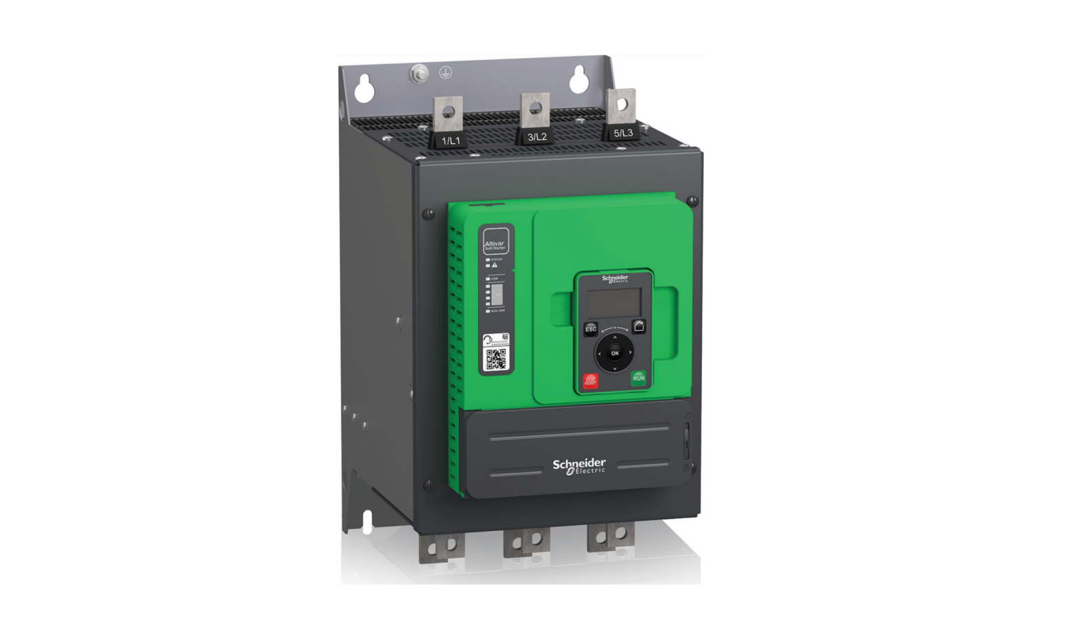
Soft Starter OverviewSoft Starter OverviewATS480D17Y…ATS480D47Y 3phase 208…690 V, 17…47 A, 2.2…45 kW, 3…50 HP
ATS480D62Y…ATS480C11Y 3phase 208…690 V, 62…110 A, 11…90 kW, 15…125 HP
Frame size AATS480C14Y…ATS480C17Y 3phase 208…690 V, 140…170 A, 30…160 kW, 40…200 HP
Frame size BATS480C21Y…ATS480C32Y 3phase 208…690 V, 210…320 A, 45…315 kW, 60… 400 HP
Frame size C
Frame size D
NNZ85515.02 07/2022
17
ATS480C41Y…ATS480C66Y 3phase 208…690 V, 410…660 A, 90…630 kW, 125…850 HP
Soft Starter OverviewATS480C79Y…ATS480M12Y 3phase 208…690 V, 790…1200 A, 220…900 kW, 250…1200 HP
Frame size E
Frame size F
ATS480 Catalog Number Description
Catalog number elements ATS480 D17Y
DescriptionProduct range, Altivar Soft Starter Factor for current rating:· D: current rating x 1 · C: current rating x 10 · M: current rating x 100 Current rating: 10 11 12 14 17 21 22 25 32 38 41 47 48 59 62 66 75 79 88 Power part supply: Y = 208…690 Vac
Manufacturing DateUse the serial number on the nameplate of the soft starter to retrieve its manufacturing date.The four digits before the 2 characters of the serial number provide respectively the year and the week of manufacture.In the example below 8A2204311382022 the manufacturing date is year 2022, week 04.
18
NNZ85515.02 07/2022
Inspect, Store and Handle the ProductInspect, Store and Handle the Product
Inspecting the Product
Unpack the soft starter and verify that it is not damaged. Damaged products or accessories may cause electric shock or unanticipated equipment operation.DANGERELECTRIC SHOCK OR UNANTICIPATED EQUIPMENT OPERATION Do not use damaged products or accessories. Failure to follow these instructions will result in death or serious injury.
Contact your local Schneider Electric sales office if you detect any damage whatsoever.
Step 12
ActionVerify that the catalog number printed on the nameplate corresponds to the purchase order.Before performing any installation work inspect the product for visible damage.
Store the product in its original packaging if not installed immediately after inspection.
Storage and Shipping
Ambient temperature Relative humidity Vibration resistanceShock resistance
NOTICEINCORRECT STORAGE Do not crush the packaging during transport and storage.Failure to follow these instructions can result in equipment damage.
Refer to the stacking instructions on the packaging. The environment during transportation and storage must be dry and free from dust.
Transport
Storage
-25…70° C (-13…158 °F)
-25…70° C (-13…158 °F)
Maximum 93 % without condensation or dripping water
· 1.75 mm peak to peak from 2 to 13 Hz· 15 m/s² from 13 to 200 Hz · 10 m/s² from 200 to 500 Hz100 m/s² at 11 ms
· 1.75 mm peak to peak from 2 to 13 Hz· 15 m/s² from 13 to 200 Hz · 10 m/s² from 200 to 500 Hz100 m/s² at 11 ms
For more information refer to Technical Data, page 277.
NNZ85515.02 07/2022
19
Inspect, Store and Handle the ProductIf the ATS480 must be shipped to another location, use the original shipping material.WARNINGINCORRECT HANDLING · Follow all handling instructions provided in this manual and in all associatedproduct documentation. · Handle and store the product in its original packaging. · Do not handle and store the product if the packaging is damaged or appearsto be damaged. · Take all measures required to avoid damage to the product and otherhazards when handling or opening the packaging. Failure to follow these instructions can result in death, serious injury, or equipment damage.To help protect the product before installation, handle and store it in its packaging. Ensure that the specified ambient conditions are followed.For ATS480C41Y to ATS480M12Y, consider this additional safety message:WARNINGTOPPLING · Take into account the high center of gravity when handling the equipment. · Only transport the equipment on the pallet using a suitable forklift. · Do not remove the straps and the screws on the pallet before the equipmenthas been transported to the final installation position. Failure to follow these instructions can result in death, serious injury, or equipment damage.
20
NNZ85515.02 07/2022
InstallationInstallation
Unpacking and Handling
Weight And Lifting Lugs Availability
See the weights, lifting lugs availability and packaging types in the following table before installing the soft starter.
References ATS480D17Y…D47Y ATS480D62Y…C11Y ATS480C14Y…C17Y ATS480C21Y…C32Y ATS480C41Y…C66Y ATS480C79Y…M12Y
Weight kg (lbs) 4.9 (10.8) 8.3 (18.2) 12.4 (27.3) 18.2 (40.1) 51.4 (113.3) 115 (253.5)
Lifting lugs No No Yes Yes Yes Yes
Packaging Cardboard box Cardboard box Cardboard box Pallet Pallet Pallet
Unpacking and Hoisting the References on PalletThe references from ATS480C21Y to ATS480M12Y are mounted on pallet.CAUTIONSHARP EDGES Use all necessary personal protective equipment (PPE) such as gloves when removing the components from the pallet.Failure to follow these instructions can result in injury or equipment damage.WARNINGTOPPLING, SWINGING, OR FALLING EQUIPMENT · Take all measures necessary to keep the equipment from swinging, topplingand falling. · Follow the instructions provided to remove the equipment from thepackaging and to mount it at its final position. Failure to follow these instructions can result in death, serious injury, or equipment damage.
NNZ85515.02 07/2022
21
Installation
See the procedure for hoisting the references from ATS480C41Y to ATS480M12Y:
Step 12 3
ActionLift the soft starter by means of a hoist by using the handling lugs of the soft starter to fasten the lifting equipment. The lifting bar is not supplied.Keep the soft starter suspended by means of appropriate equipment until it is securely fastened in the final installation position.Move the soft starter to the final installation or on the back of the enclosure in accordance with the instructions given in this document.
a b
· a: 45° maximum · b: Lifting barSoft Starter MountingBefore you BeginConductive foreign objects may cause parasitic voltage.DANGERELECTRIC SHOCK AND/OR UNANTICIPATED EQUIPMENT OPERATION · Keep foreign objects such as chips, screws or wire clippings from getting intothe product. · Verify correct seat of seals and cable entries in order to avoid deposits andhumidity. Failure to follow these instructions will result in death or serious injury.
22
NNZ85515.02 07/2022
Installation
The temperature of the products described in this manual may exceed 80 °C (176 °F) during operation.WARNINGHOT SURFACES · Ensure that any contact with hot surfaces is avoided. · Do not allow flammable or heat-sensitive parts in the immediate vicinity ofhot surfaces. · Verify that the product has sufficiently cooled down before handling it. · Verify that the heat dissipation is sufficient by performing a test run undermaximum load conditions. Failure to follow these instructions can result in death, serious injury, or equipment damage.
Mounting in an Enclosure
DANGERHAZARD OF ELECTRIC SHOCK, EXPLOSION, OR ARC FLASH These products are open devices and must be mounted in a suitable enclosure.Failure to follow these instructions will result in death or serious injury.
Use the enclosure manufacturers’ specifications for proper sizing based on thermal considerations. It is necessary to add up the power dissipated by each device in the enclosure.For the power dissipated by the soft starter refer to Soft Starter Cooling and Power Dissipation, page 25.
Enclosure type General purpose metalto reach IP23
Dust and damp-proof metal to reach IP54 / NEMA12
ee = external ambient temperaturei = internal ambient temperature of the enclosure
i ATS
e
i
ATS
e i ATS
Air circulationTemperature around the soft starter
Install air inlet
If air inlet is not adequate, install a forced ventilation unit, with a filter if necessary
Do not use insulated or nonmetallic enclosures as they have poor thermal conduction. Provide a stirring fan to circulate air inside the enclosure and to help prevent hot spots in the soft starter.This allows operation of the soft starter in an enclosure with a maximum internal temperature of 60 °C (140 °F)
· -10…40 °C (14…104 °F) without derating when not bypassed · -10…50 °C (14…122 °F) without derating when bypassed · 40…60 °C (104 … 140 °F) with rated current (Ie) derating of 2% per degree Ensure that the ambient temperature around the soft starters does not exceed this limit.
NNZ85515.02 07/2022
23
InstallationMounting PositionThe soft starter is designed to be mounted inside cabinets vertically at ± 10° for cooling purposes.Respect the minimum clearances so that the cooling air can circulate from the bottom to the top of the soft starter. The minimum clearances apply to any device close to the soft starter such as circuit breakers, fuses, contactors, bypass contactors.Do not install the soft starter above heating elements.
mm
mm
in.
in.
100
(3.9)
50
50
10
(1.9)
(1.9)
(0.4)
100 (3.9)10°
24
NNZ85515.02 07/2022
InstallationSoft Starter Cooling and Power Dissipation
ReferenceATS480D17Y ATS480D22Y ATS480D32Y ATS480D38Y ATS480D47Y ATS480D62Y ATS480D75Y ATS480D88Y ATS480C11Y ATS480C14Y ATS480C17Y ATS480C21Y ATS480C25Y ATS480C32Y ATS480C41Y ATS480C48Y ATS480C59Y ATS480C66Y ATS480C79Y ATS480M10Y ATS480M12Y
Frame Power Dissipated at
Power Dissipated at
Size Nominal Load in Normal Heavy Load in Normal
Duty, not Bypassed (W) Duty, not Bypassed (W)
A
63
A
79
A
109
A
121
A
147
B
206
B
250
B
295
B
327
C
391
C
484
D
585
D
700
D
907
E
1344
E
1391
E
1736
E
1963
F
2542
F
2870
F
3497
51 64 79 104 121 158 206 250 257 311 396 473 585 700 1022 1177 1391 1736 2078 2230 2870
Minimum air flow rate required
m³/hour ft³/min
No fan
No fan
14
8
14
8
28
16
86
50
86
50
86
50
86
50
138
81
138
81
280
164
280
164
280
164
600
353
600
353
600
353
600
353
1200
706
1200
706
1200
706
Fans switch to On as soon as the heatsink temperature reaches 50°C (122°F). Fans switch to Off as soon as the heatsink temperature falls below 40°C (104°F).When bypassed, the soft starter dissipates 25 W with fans Off and 110 W maximum.
.
NNZ85515.02 07/2022
25
Dimensions
InstallationUse screws with DIN 125 washer to mount the soft starter. Tighten the fixing screws. Altivar Soft Starter ATS480 CAD files can be downloaded from www.se.com.
ATS480D17Y…ATS480D47YFront, Side and Rear View, frame size A
mm in.160 6.3
mm in.203 8
mm
in.
30
100
30 Ø7
1.1
3.9
1.1 0.27
6.6 0.26
10.2
260
10.8
275
Mounting screws x 4: M6
Ø7
8.4
0.27
0.3
ATS480D62Y…ATS480C11YFront, Side and Rear View, Frame size B
mm
in.
190
7.4
mm
in.
247
9.72
mm
150
in. 20 5.9 20
Ø7
0.78
0.78 0.27
10 0.39
10.6
270
11.4
290
Mounting screws x 4: M6 26
Ø7
10
0.27
0.39
NNZ85515.02 07/2022
InstallationATS480C14Y…ATS480C17YFront, Side and Rear View, frame size C
mm
in.
200
7.8
mm
in.
272
10.7
mm
160
in.
20 6.3 20
0.7
0.7
Ø7
0.27
10
0.4
340 13.3 320 12.6
Ø7 0.27Mounting screws x 4: M6
ATS480C21Y…ATS480C32YFront, Side and Rear View, frame size D
mm in.320 12.6
mm in.277 10.9
mmin. 35Ø9 1.3 0.35
10 0.4
250
35
9.8
1.3
15 0.6
350
380 14.9
0.6
15
Ø9 0.35Mounting screws x 4: M8
13.7
NNZ85515.02 07/2022
27
ATS480C41Y…ATS480C66YFront, Side and Rear View, frame size E
mm in.400 15.7
mm in.314 12.3
Installation
670 26.3
mm in.
Ø9
50
300
50
0.35
2
11.8
2
Mounting screws x 4: M8
20 0.78
24
610
Ø9 0.3528
40
1.57
NNZ85515.02 07/2022
InstallationATS480C79Y…ATS480M12YFront, Side and Rear View, frame size F
mm in.770 30.3
mm in.329 13
890 35
mm
in.
350
Ø11
35 13.7
0.4
1.3
Mounting screws x 6: M10
350
13.7
35
1.3
20 0.78
33.4
850
0.78
Ø11 0.4
20
NNZ85515.02 07/2022
29
Installing Door Mounting Kit
Installation
The ATS480 is delivered with the VW3A1113 Plain Text Display Terminal.The VW3A1111 Graphic Display Terminal is available as an option to replace the Plain Text Display Terminal.Door mounting kits are available as options to mount the display terminal on the door of the enclosure.Refer to the following table to choose a display terminal and its door mounting kit.
Door Mounting Kit protection degree IP43
Display terminalVW3A1113 Plain Text Display Terminal Delivered with the soft starter
Door mounting kitVW3A1114 door mounting kit. Available as option
IP65
VW3A1111 Graphic Display Terminal Available as option
Refer to the instruction sheet EAV91355. VW3A1112 door mounting kit. Available as option
Select one of the following RJ45 cables to connect the remote mounting kit to the soft starter:· 1 meter: VW3A1104R10 · 3 meters: VW3A1104R30 · 5 meters: VW3A1104R50 · 10 meters: VW3A1104R100 Not included with the remote kit
Refer to the instruction sheet EAV76406.
30
NNZ85515.02 07/2022
InstallationProtective Covers For ATS480C41Y…M12YIt is possible to limit direct access to the power terminals by installing protective covers for the following references:· ATS480C41Y · ATS480C48Y · ATS480C59Y · ATS480C66Y · ATS480C79Y · ATS480M10Y · ATS480M12Y Protective covers help to add a guarding to the IP00 power terminals to reduce accidental contact.DANGERHAZARD OF ELECTRIC SHOCK OR ARC FLASH · Do not consider that the degree of protection is modified if the protectivecovers are added to the device. · Before performing any work on and around the device, you must continue tofollow the instructions given in this manual. Failure to follow these instructions will result in death or serious injury.NOTICEDAMAGE TO THE DEVICE · Follow the instructions given in this section to design and install theprotective covers. · Do not exceed the maximum limits specified. Failure to follow these instructions can result in equipment damage.To dimension the protective covers, it is required to respect the following limits: · Protective cover material must be polymethyl methacrylate (PMMA) · M6 fixing screws · Maximum 5 mm (0,2 inch) thick · Same width as the soft starter: 400 mm (15,7 inches) for ATS480C41Y…ATS480C66Y 770 mm (30;3 inches) for ATS480C79Y…ATS480M12Y · Maximum length below and above the soft starter: 220 mm (8,6 inches) for ATS480C41Y…ATS480C66Y 250 mm (9,8 inches) for ATS480C79Y…ATS480M12YFor a longer length, it is required to use support points on the cabinet.
NNZ85515.02 07/2022
31
The following measurements are in millimeters (inches).
ATS480C41Y…ATS480C66Y
ATS480C79Y…ATS480M12Y
14
188,5
(0.55) (7.4)
188,5 (7.4)
43 (1.7)
345 (13.6)
345 (13.6)
Installation
250 (9.8) 43,25 (1.7)
3xM6
3xM6
83,25 (3.3) 220 (8.6)
773,25 (30.4) 710,25 (28) 45,5 (1.8)
500 (19.7)
3xM6
3xM6
250 (9.8)
220 (8.6)
32
NNZ85515.02 07/2022
InstallationFieldbus ModulesFieldbus Modules can be used with the soft starter for communicating with the product, applying commands and monitoring. For the list of Fieldbus Manuals refer to Related Documents, page 14.
NNZ85515.02 07/2022
33
WiringWiringGeneral instructionsDANGERHAZARD OF ELECTRIC SHOCK, EXPLOSION OR ARC FLASH Read and understand the instructions in Safety Information chapter before performing any procedure in this chapter.Failure to follow these instructions will result in death or serious injury.DANGERHAZARD OF FIRE OR ELECTRIC SHOCK · Wire cross sections and tightening torques must comply with thespecifications provided in this document. · If you use flexible multi-wire cables for a connection with a voltage higherthan 25 Vac, you must use ring type cable lugs or wire ferrules, depending on the wire gauge and the specified stripping length of the cable. Failure to follow these instructions will result in death or serious injury.The product has a leakage current greater than 3.5 mA. If the protective ground connection is interrupted, a hazardous touch current may flow if the product is touched.DANGERELECTRIC SHOCK CAUSED BY HIGH LEAKAGE CURRENT Verify compliance with all local and national electrical code requirements as well as all other applicable regulations with respect to grounding of the entire drive system installation.Failure to follow these instructions will result in death or serious injury.DANGERINSUFFICIENT PROTECTION AGAINST OVERCURRENTS CAN CAUSE FIRE OR EXPLOSION · Use properly rated overcurrent protection devices. · Use the fuses/circuit breakers specified. Failure to follow these instructions will result in death or serious injury.DANGERHAZARD OF ELECTRIC SHOCK, EXPLOSION, OR FIRE The opening of the branch-circuit protective device is able to be an indication that a fault current has been interrupted. · Current-carrying parts and other components of the controller should beexamined and replaced if damaged. · If burnout of the current element of an overload relay occurs, the completeoverload relay must be replaced. Failure to follow these instructions will result in death or serious injury.
34
NNZ85515.02 07/2022
Wiring
The products may perform unexpected movements because of incorrect wiring, incorrect settings, incorrect data or other errors.WARNINGUNANTICIPATED EQUIPMENT OPERATION· Carefully install the wiring in accordance with the EMC requirements.· Do not operate the product with unknown or unsuitable settings or data.· Perform a comprehensive commissioning test.Failure to follow these instructions can result in death, serious injury, or equipment damage.Refer to the following instructions to wire the soft starter:· Do not route signal cables next to power cables.· Cables connected to the motor must have the maximum possible separation from all other power cables. Do not run them in the same conduit. This separation reduces the possibility of coupling electrical noise between circuits.· Voltage and frequency specifications for the supply mains must match the soft starter configuration.· A disconnect switch must be installed between the supply mains and the soft starter.· Power factor correction capacitors should not be connected to a motor controlled by a soft starter. If power factor correction is required, the capacitors must be located on the mains of the soft starter. A separate contactor should be used to switch the capacitors off when the motor is off, or during acceleration and deceleration. Use the relay R2 or R3 to switch the contactors.· The soft starter must be grounded to conform to the regulations concerning leakage currents. If the installation involves several soft starters on the same supply mains, each soft starter must be grounded separately.
NNZ85515.02 07/2022
35
Power Terminals
Power Connections ATS480D17Y…ATS480C11Y
Mains side
L1
L2
L3
Motor side (bottom)
1/L1
3/L2
5/L3
2/T1
4/T2
6/T3
A2
B2
C2
Wiring
A2 2T1 B2 4T2 C2 6T3
U1
V1
W1
M
Use class C cables for the power connections. · 1/L1, 3/L2, 5/L3: Mains supply inputs · 2/T1, 4/T2, 6/T3: Outputs to motor · A2, B2, C2: Soft starter bypassSimple diagrams for the power connections are available at Connection Of The Motor and Supply Mains, page 41.Complete application diagrams including power and control connections are available at Application Diagrams, page 51.
36
NNZ85515.02 07/2022
Wiring
ReferencesATS480D17Y ATS480D22Y ATS480D32Y ATS480D38Y ATS480D47Y ATS480D62Y ATS480D75Y ATS480D88Y ATS480C11Y
Current level (in fraction of the soft starterrating)0,4 1 1,3 0,4 1 1,3 0,4 1 1,3 0,4 1 1,3 0,4 1 1,3 0,4 1 1,3 0,4 1 1,3 0,4 1 1,3 0,4 1 1,3
Power connectors 1/L1, 3/L2, 5/L3, 2/T1, 4/T2, 6/T3, A2, B2, C2
Wire cross section (a) (b)
Stripping length
Tightening torque
mm² (AWG)
Minimum mm Maximum mm
(in)
(in)
N.m (lbf.in)
2.5 (12)
8 (0.3)
10 (0.4)
3 (26)
2.5 (12)
4 (10)
2.5 (12)
8 (0.3)
10 (0.4)
3 (26)
4 (10)
6 (10)
2.5 (12)
8 (0.3)
10 (0.4)
3 (26)
6 (10)
10 (8)
2.5 (12)
8 (0.3)
10 (0.4)
3 (26)
10 (8)
10 (8)
2.5 (12)
8 (0.3)
10 (0.4)
3 (26)
10 (8)
10 (8)
4 (10)
19 (0.3)
21 (0.8)
10 (89)
16 (6)
25 (4)
6 (10)
19 (0.3)
21 (0.8)
10 (89)
25 (4)
35 (3)
10 (8)
19 (0.3)
21 (0.8)
10 (89)
35 (3)
35 (2)
10 (8)
19 (0.3)
21 (0.8)
10 (89)
35 (2)
35 (1/0)
(a) The cable gauge affects the IP protection degree. IP20 protection degree requires a minimum cable gauge of 16 mm² (4 AWG) and end caps. If this condition is not met, the IP protection degree is IP10. (b) The cross section cable values are given for one cable per cages. The good behavior of the ATS480 is not assured with more than one cable per cages.
NNZ85515.02 07/2022
37
ReferencesATS480D17Y…D47Y ATS480D62Y…C11Y
Ground Connection Characteristics:
Section mm² (AWG)10 (10)
Tightening torque N.m (lbf.in) 1.7 (15)
16 (6)
3 (26)
Power Connections ATS480C14Y…ATS480M12Y
Mains side
L1
L2
L3
Motor side (bottom)
1/L1
3/L2
5/L3
A2 2/T1
B2 4/T2
C2 6/T3
Wiring Screw sizeM6
2/T1
4/T2
6/T3
d1 d3
U1
V1
W1
M
d2
1/L1
3/L2
5/L3
NOTE: Do not access the power bars when the supply mains is On.
NOTE: Do not access the power bars when the supply mains is On.
· 1/L1, 3/L2, 5/L3: Mains supply inputs· 2/T1, 4/T2, 6/T3: Outputs to motor· A2, B2, C2: Soft starter bypassSimple diagrams for the power connections are available at Connection Of The Motor and Supply Mains, page 41.Complete application diagrams including power and control connections are available at Application Diagrams, page 51.
38
NNZ85515.02 07/2022
Wiring
References
Current level (as afraction of the soft starter rating)
ATS480C14Y
0,4
1
1,3
ATS480C17Y
0,4
1
1,3
ATS480C21Y
0,4
1
1,3
ATS480C25Y
0,4
1
1,3
ATS480C32Y
0,4
1
1,3
ATS480C41Y
0,4
1
1,3
ATS480C48Y
0,4
1
1,3
ATS480C59Y
0,4
1
1,3
ATS480C66Y
0,4
1
1,3
Power connectors 1/L1, 3/L2, 5/L3, 2/T1, 4/T2, 6/T3, A2, B2, C2
Section
Tightening torque
Bar
mm² (AWG)
N.m (lbf.in)
d1 mm (in)
d2 mm (in)
d3 mm (in)
16 (6)50 (1/0)95 (3/0)25 (4)70 (2/0)95 (4/0)25 (4)95 (4/0)150 (300 kcmil)35 (3)120 (250 kcmil)185 (400 kcmil)50 (1)185 (400 kcmil)2×150 (2×250 kcmil)70 (2/0)2×150 (2×250 kcmil)2×185 (2×350 kcmil)95 (AWG3/0)2×150 (2×250 kcmil)2×185 (2×350 kcmil)120 (250 kcmil)2×185 (2×350 kcmil)2×240 (3×300 kcmil)150 (300 kcmil)2×240 (3×300 kcmil)Cu bar 2x (60x5mm) (2×0.25″)
34 (300)
20 (0.8) 5 (0.2) 9 (0.3)
34 (300)
20 (0.8) 5 (0.2) 12 (0.5)
57 (500)
40 (1.5) 5 (0.2) 14 (0.5)
NNZ85515.02 07/2022
39
Wiring
References
Current level (as afraction of the soft starter rating)
ATS480C79Y
0,4
1
1,3
ATS480-
0,4
M10Y
1
1,3
ATS480-
0,4
M12Y
1
1,3
Power connectors 1/L1, 3/L2, 5/L3, 2/T1, 4/T2, 6/T3, A2, B2, C2
Section
Tightening torque
Bar
mm² (AWG)
N.m (lbf.in)
d1 mm (in)
d2 mm (in)
d3 mm (in)
185 (400 kcmil)2×240 (3×300 kcmil)Cu bar 2x (80x5mm) (2.5×0.25″)2×150 (2×250 kcmil)Cu bar 2x (60x5mm) (2×0.25″)Cu bar 2x (100x5mm)(3×0.25″)2×150 (2x250kcmil)Cu bar 2x (80x5mm) (2.5×0.25″)Cu bar 2x (100x5mm)(3×0.25″)
57 (500)
60 (2.3) 5 (0.2) 14 (0.5)
ReferencesATS480C14Y…C17Y ATS480C21Y…C32Y ATS480C41Y…C66Y ATS480C79Y…M12Y
Ground Connection Characteristics:
Section mm² (AWG)35 (4) 95 (3) 240 (2/0) 300 (4/0)
Tightening torque N·m (lbf.in) 4.5 (40) 24 (212) 24 (212) 24 (212)
Screw sizeM6 M10 M10 M10
40
NNZ85515.02 07/2022
Wiring
Connection Of The Motor and Supply Mains
Connection In-Line
L1
L2
L3
1/L1 3/L2 5/L3
The soft starter can be connected inline to the motor supply. The motor connection type (star/delta) depends on(a) the supply mains, refer to the motor nameplate.· (a): Supply mains· (b): Soft starter· (c): Induction motor
(b)
2/T1 4/T2 6/T3
U1
V1
W1
(c)
Bypassing The Soft Starter
L1
L2
L3
The soft starter can be bypassed with a contactor (K) at end
(a)
of start. The bypass contactor can be controlled by the soft starter, using the relay R2. The monitoring functions such as
current measurement remain active when the soft starter is
bypassed.
Bypassing soft starter limits heat dissipation of the SCR, which allows:· To downsize the soft starter by one current rating (b) · More starts per hour· Higher starting current · Longer starting time · (a): Supply mains · (b): Soft starter · (c): Induction motor · K: External bypass connector
(c)
NNZ85515.02 07/2022
41
WiringConnection In The Motor Delta Winding
L1 L2 L3
(a)
1/L1 3/L2 5/L3 (b)2/T1 4/T2 6/T3U1 V1 W1 (c)W2 U2 V2
The Soft starter can be connected in series with motor windings in a delta connection (inside the delta connection). By doing so, for the same motor power rating, the current going through the winding and the soft starter is reduced by 1.7 (3). This reduction allows to choose a soft starter with lower current rating.Example:Using a 400V 110kW 4 pole motor with a mains supply current of 195A (nominal current for the delta connection).· In-line connection: a soft starter is selected with a current rating just above 195A, i.e. ATS480C21Y (210A) for a normal duty application.· Inside delta connection: the current in each winding is equal to 195/3 = 114A, ATS480C14Y is sufficient for this normal duty application.· (a): Supply mains· (b): Soft starter· (c): Induction motorFor more information about the parameters enabling insidedelta usage, refer to Connection Inside The Delta Of The Motor, page 104.
42
NNZ85515.02 07/2022
WiringControl TerminalsDANGERHAZARD OF FIRE OR ELECTRIC SHOCK · Wire cross sections and tightening torques must comply with thespecifications provided in this document. · If you use flexible multi-wire cables for a connection with a voltage higherthan 25 Vac, you must use ring type cable lugs or wire ferrules, depending on the wire gauge and the specified stripping length of the cable. Failure to follow these instructions will result in death or serious injury.When the soft starter transitions to operating state Fault, the mains contactor must be deenergized.WARNINGUNANTICIPATED EQUIPMENT OPERATION · Connect the coil of the mains contactor to output relay R1. Failure to follow these instructions can result in death, serious injury, or equipment damage.Control Terminals Layout
R2A R2C R3A R3CSTOP RUNDI3 DI4
STOP RUN
0V
+24
PTC3
PTC2
AI1
PTC1
COM
AQ1
DQ+
DQ2
DQ1
R1CCL2
R1A
230V MAX
AI1
CL1
PTC shielded cable screw
Modbus VP12S
The control terminals are installed with one-way plug-in connectors. Ferrules are mandatory for wiring the CL1 and CL2 terminals to ensure an IP20 protection. The terminals are approved for stranded conductors and solid conductors. Use wire cable ends (ferrules) if possible.NOTE:· Do not access the terminals CL1 and CL2 when the soft starter is supplied.· Modbus VP12S: This is the standard Modbus serial link marking. VPS means connector with power supply, where 12 stands for the 12 Vdc supply voltage.
NNZ85515.02 07/2022
43
Tightening torque max N.m (lbf.in)0.5 (4.4)
Wiring
NOTICEINCORRECT VOLTAGE· Supply the control supply terminals CL1 / CL2 within a range of 110…230 Vac only· In case of migration from ATS48Q to ATS480Y, adapt the control supply transformerFailure to follow these instructions can result in equipment damage.
Min relay output wire cross section mm² (AWG) 0.75 (18)
Other min wire cross sectionmm² (AWG) 0.5 (20)
Max connection capacitymm² (AWG) 2.5 (13)
Stripping length mm (in)
Min
Max
5.5 (0.2)
7.5 (0.3)
Those values are given for a single wire per terminal. Use a shunt to create a bridge between terminals if necessary.
Control Block Wiring Diagram
R1A R1C R2A R2C R3A R3C AQ1 COM PTC1AI1 PTC2 PTC3
CL1 CL2 DQ1 DQ2 DQ+ STOP RUN DI3 DI4 +24 0V
0-10 Vdc
(b)
x-20 mA
ATS480
110…230Vac (a)· (a): Control supply 110…230 Vac · (b): 2 wire PTC/PT100 PT100 Thermal Probe 3 Wires:
24 V +24 V 0 V
PTC1 AI1PTC2 PTC3
(c)(c): 3 wire PT10044
NNZ85515.02 07/2022
Wiring
Control Terminal Characteristics
The ATS480 can start and stop the motor in “2wire control” or “3wire control”, depending on how the STOP and RUN terminals are wired. Simple diagrams explaining those two modes and how to wire the terminals STOP and RUN are available at Connection Of The Motor and Supply Mains, page 41.Complete application diagrams including power and control connections are available at RUN and STOP Management, page 46.The ATS480 control part can be supplied by the +24 terminal, allowing to keep the communication with the soft starter but with no possibilities to control the motor. To control the motor, the ATS480 must be supplied in 110…230 Vac via the terminals CL1 and CL2.
Reference ATS480D17Y…D22Y ATS480D32Y…C17Y ATS480D21Y…C41Y ATS480C48Y…C66Y ATS480C79Y…M12Y
Control block apparent power (VA) supply 60 90 106 125 200
Terminals CL1 CL2 R1A R1C R2A R2C R3A R3CSTOPRUN DI3 DI40V +24
Function Control power supply
I/O Characteristics
I
· 110…230 Vac +10% 15%, 50/60 Hz
Programmable NO relay R1
O
Assigned to Operating state Fault
by default
NO relay R2 Assigned to End of O starting. Will close when the soft starter is in established regime.
Programmable NO relay R3
O
Digital Input 1 — Assigned to
I
STOP
Digital Input 2 — Assigned to RUN I
Digital Input 3
I
Digital Input 4
I
Common for +24
I/O
Supply for digital output
I/O
· Max voltage: 230 Vac.· Min. switching capacity: 10 mA for 24 Vdc· Max. switching capacity on inductive load following IEC60947-2:2A/250Vac for AC15 100 000 cycles2A/30Vdc for DC13 150 000 cyclesInductive load must be equipped with a voltage surge suppression device according to ac or dc operation with total energy dissipation greater than the inductive energy stored in the load.Refer to sections Output Relay with Inductive AC Loads, page 48 and Output Relay with Inductive DC Loads, page 49.· 4 x 24 Vdc digital inputs with 4.3 k impedance· Umax = 30 V· Imax = 8 mA· State 1: U > 11 V and I > 5 mA· State 0: U < 5 V and I < 2 mA· Response time: 2 ms ± 0.5 ms max· 0V· Umin: 19 Vdc· Unominal: 24 Vdc· Umax: 30 Vdc· Imax: 200 mA· Isolated and protected against short-circuits and overloads, maximum current 200 mA.· Can be used to supply the control block with an external 24Vdc supply if CL1 and CL2 are absent to keep communication with the product NOTE: The +24 terminal does not entirely substitute supply from CL1 and CL2. The motor cannot be controlled if you supply the ATS480 via only the +24 terminal. To control the motor, the ATS480 must be supplied via CL1 and CL2.
NNZ85515.02 07/2022
45
Wiring
Terminals DQ+ DQ1 DQ2AQ1COM PTC1 / AI1 PTC2 PTC3
Function Digital output supply Programmable digital output 1 Programmable digital output 2Programmable analog Output 1I/O common Motor thermal sensor connection
I/O Characteristics
O
· 24 Vdc digital output supply
O
· 2 open collector outputs compatible with level 1 PLC,
IEC 65A-68 standard.
O
· Power supply +24 Vdc (min. 12 Vdc, max 30 Vdc)
· Max. current 100 mA per output with an external source
· Max frequency: 1kHz
O
· Available signal: 0 10 Vdc 0 20 mA, can be
configured as 4 20 mA
· Accuracy ± 1% for temperature range –10 to +60°C
· Resolution: 10 bits
· Linearity: ± 0.2%
· Sampling time: 5 ms + 1 ms maximum
· Applicable load: 470 min, 470 max
I/O · 0 V
I
· Configurable for PTC and PT100 (2/3 wires)
· Total resistance of sensor circuit 750 at 25°C
· Overheat trigger threshold: 2.9 k ± 0.2 k
· Overheat reset threshold: 1.575 k ± 0.75 k
· Threshold for low impedance detection: 50 k 10 / +20
· Protected for low impedance < 1000
Refer to [Thermal monitoring] TPP, page 139 for more information on thermal sensors.
RUN and STOP Management2wire controlRun and Stop are controlled by state 1 (closed, active) or 0 (open, inactive), on the Run and Stop terminals. At power-up or on manual error reset, the motor will start if RUN is active.
STOP RUN DI3 DI4 +24V
V (a)
V
t
(b)
V
t
(c)S1t
· V: Voltage · t: Time · (a): Control supply (CL1 / CL2 terminals) · (b): Run order (Stop / Run terminals) · (c): Motor rotation
46
NNZ85515.02 07/2022
STOP RUN DI3 DI4 +24V
WiringS1 S2
3wire controlRun and Stop are controlled by 2 different digital inputs. The Stop order is applied at low level on the Stop terminal. The Run order is applied at high level on the Run terminal only if Stop terminal is at high level.On Power-up or manual Error Reset or after a Stop command coming from the active channel command, the motor will be powered if a Run command is active. If a Stop command is applied via a different channel command, the motor can only be powered again by removing the active Run command and applying a new one.
V(a)
V
t
(b)
V
t
(c)
V
t
(d)
t· V: Voltage · t: Time · (a): Control supply (CL1 / CL2 terminals) · (b): Stop terminal logic level · (c): Run terminal logic level · (d): Motor rotation
Applying a Run order when [Fault Reset Assign] RSF is set to [Not Assigned] NO will reset the soft starter. A second Run order is necessary to restart the motor.
NNZ85515.02 07/2022
47
Wiring
Relay Contacts Wiring
General
The AC voltage source must be of overvoltage category II (OVC II) according to IEC 60947-4-2 and IEC 60947-1.If it is not the case, an isolation transformer must be used.
Contactors with AC CoilIf controlled by a relay, a resistor-capacitor (RC) circuit must be connected in parallel to the coil of the contactor as shown on the drawing below.
(1)
R C
R1A R1B R1C R2A R2C
ATS(1) AC 250 Vac maximum. Schneider Electric AC contactors have a dedicated area on the housing to plug easily the RC device. Refer to the Motor control and protection components catalog MKTED210011EN available on se.com to find the RC device to be associated with the contactor used. Example: With a 48 Vac source, contactors LC1D09E7 or LC1DT20E7 have to be used with LAD4RCE voltage suppression device.Other Inductive AC LoadsFor other inductive AC loads: · Use an auxiliary contactor connected on the product to control the load. Example: with a 48 Vac source, auxiliary contactors CAD32E7 or CAD50E7 with LAD4RCE voltage suppression device. · When using a third-party inductive AC load, request the supplier to provide information on the voltage suppression device, in order to avoid overvoltage above 375 V during relay opening.
48
NNZ85515.02 07/2022
WiringContactors with DC CoilIf controlled by a relay, a bidirectional transient voltage suppression (TVS) diode, also called transil, must be connected in parallel to the coil of the contactor as shown on the drawing below.
+
(1)
(2)
R1A R1B R1C R2A R2C
ATS(1) DC 30 Vdc maximum. (2) TVS diode Schneider Electric contactors with DC coil include the TVS diode. No additional device is required. Refer to the Motor control and protection components catalog MKTED210011EN available on se.com for more information.
NNZ85515.02 07/2022
49
WiringOther Inductive DC LoadsOther inductive DC loads without embedded TVS diode must use one of the following voltage suppression device:· A bidirectional TVS device as shown on the drawing above, defined by: TVS break-down voltage greater than 35 Vdc, TVS clamping voltage V(TVS) less than 50 Vdc TVS peak power dissipation greater than load rated current, I(load) x V (TVS). Example: with I(load) = 0.9 A and V(TVS) = 50 Vdc, TVS peak power must be greater than 45 W TVS average power dissipation greater than the value calculated by the following 0.5 x I(load) x V(TVS) x load time constant x number of operation per second. Example: with I(load) = 0.9 A and V(TVS) = 50 Vdc, load time constant = 40 ms (load inductance divided by load resistance) and 1 operation every 3 s, the TVS average power dissipation must be greater than 0.5 x 0.9 x 50 x 0.04 x 0.33 = 0.3 W.· A fly-back diode as shown in the drawing below.
+
(1)
(2)
R1A R1B R1C R2A R2C
ATS(1) DC 30 Vdc maxi. (2) Flyback diode The diode is a polarized device. The fly-back diode must be defined by:· A reverse voltage greater than 100 Vdc, · A rated current greater than two times the load rated current, · A thermal resistance: junction to ambient temperature (in K/W) less than 90 /(1.1 x I(load)) to operate at maximum 60°C (140°F) ambient temperature. Example: with I(load) = 1.5 A, select a 100 V, 3 A rated current diode with a thermal resistance from junction to ambient less than 90 / (1.1 x 1.5) = 54.5 K/ W. Using a flyback diode, the relay opening time will be longer than with a TVS diode. NOTE: Use diodes with leads for easy wiring and keep at least 1 cm (0.39 in.) of leads on each side of the case of the diode for a correct cooling.
50
NNZ85515.02 07/2022
WiringApplication DiagramsConnection In Line, With Line Contactor, No Bypass, Type 1 or 2 Coordination, 2-wire or 3-wire controlLine contactor controlled by Power ON and Power OFF push-buttons or on detected errorThis application diagram is well adapted to local control using inputs of ATS480. It requires a local intervention to restart after the error reset even in case of remote control: press S3 push button to restart. Use relay output R1 set to [Operating State Fault] FLT (factory setting) to turn Off the soft starter when an error is detected.
14 13
Q1 KM1 Q3 A1
2
1
2
1
4
3
4
3
6
5
6
5
-Q2 12 34
(3)
T1
Q4
1
2
3 4 12
Q5 (1)(3)
A2 A1
Q1
S1 S2
14 13
S3
KM1
R1A A1
(2)
R1C
KM1
(5)
2/T1 1/L1 4/T2 3/L2 6/T3 5/L3 STOP RUN DI3 DI4 +24V DQ+ DQ1 DQ2 AQ1 CL1 COM CL2 PTC1/AI1 PTC2 PTC3 R1A R1C R2A R2C R3A R3C
U1 V1 W1 STOP RUN +24V STOP +24V
S 4 S 5(4)M 3
S6
(4)
(4)
· (1) Installation of additional fast-acting fuses is mandatory to upgrade to type 2 coordination according to IEC 6094742. · (2) Take into account the electrical characteristics of the relays, refer to Control Terminal Characteristics, page 45. · (3) The transformer must supply 110…230 Vac +10% – 15%, 50/60Hz. · (4) 3wire control, 2wire control and fieldbus control. Refer to RUN and STOP Management, page 46. · (5) To select the appropriate voltage surge suppressor refer to Relay Contacts Wiring, page 48.
Designation Component
Q1
Circuit breaker
Q2
Circuit breaker
Q3
Fast acting fuses
Q4 Q5 KM1 S1 S2 S3
Circuit breaker Circuit breaker Contactor Emergency Stop push-button Normally close push-button Normally open push-button
DescriptionShort circuit protection device for the motorShort circuit protection device for the primary of the transformerShort circuit protection device of the soft starter to be used only when type 2 coordination Short circuit protection device for the secondary of the transformer Short circuit protection device for the control part of the soft starter Line contactorEmergency Stop to de-energized KM1 line contactorPower OFFPower ON
NNZ85515.02 07/2022
51
Designation Component
S4
Normally close contact push-button
S5
Normally open contact push-button.
S6
Selector switch, 2 positions, stay put, normally open
contact
Description STOP command for 3-wire control RUN command for 3-wire control RUN/STOP command for 2-wire control
Wiring
Connection In Line, With Line Contactor, No Bypass, Type 1 or 2 Coordination, 2-wire controlLine contactor controlled based on RUN & STOP or on detected error. Freewheel stop only.Simplified application diagram for local control using inputs of ATS480. Use relay output R1 set to [Isolating Relay] ISOL to turn Off the soft starter when an error is detected or on STOP command.
14 13
Q1 KM1 Q3 A1
2
1
2
1
4
3
4
3
6
5
6
5
-Q2 12 34
(3)
T1
1 Q4 2
3 4 12
Q5 (1)(3)
A2 A1
Q1
S1 S2
14 13
S3
KM1 A1
R1A (2)
R1C
KM1
(5)
U1 2/T1 1/L1V1 4/T2 3/L2W1 6/T3 5/L3 STOP RUN DI3 DI454 53 +24V DQ+ DQ1 DQ2 AQ1 CL1 COM CL2 PTC1/AI1 PTC2 PTC3 R1A R1C R2A R2C R3A R3C
KM1(4) M1 3
· (1) Installation of additional fast-acting fuses is mandatory to upgrade to type 2 coordination according to IEC 6094742. · (2) Take into account the electrical characteristics of the relays, refer to Control Terminal Characteristics, page 45. · (3) The transformer must supply 110…230 Vac +10% – 15%, 50/60Hz. · (4) 2wire control. Refer to RUN and STOP Management, page 46. · (5) To select the appropriate voltage surge suppressor refer to Relay Contacts Wiring, page 48.
Designation Component
Q1
Circuit breaker
Q2
Circuit breaker
Q3
Fast acting fuses
Q4
Circuit breaker
Description Short circuit protection device for the motor Short circuit protection device for the primary of the transformerShort circuit protection device of the soft starter to be used only when type 2 coordination according to IEC 60947-4-2 is requiredShort circuit protection device for the secondary of the transformer
52
NNZ85515.02 07/2022
Wiring
Designation Component
Q5
Circuit breaker
KM1 S1
Contactor Emergency Stop push-button
S2
Normally close push-button
S3
Normally open push-button
Description Short circuit protection device for the control part of the soft starter Line contactor Emergency Stop to de-energized KM1 line contactor Power OFF and freewheel stop Power ON and Run order
Connection In Line, With Line and Bypass Contactor, Freewheel Or Controlled Stop, Type 1 or 2 Coordination, 2-wire or 3-wireLine contactor controlled by Power ON and Power OFF push-buttons or detected errorThis application diagram requires a local intervention to restart after the error reset even in case of remote control: press S3 push button to restart. Use relay R1 set to [Operating State Fault] FLT (factory setting) to turn Off the soft starter when an error is detected.
14 13
1
3
Q1 KM1 Q2 A1 KM3
5
2
1
2
1
4
3
4
3
6
5
6
5
Q3 12 12
(3)
T1
Q4 12
Q1
S1
S 2
R 1A
A1
S3
(2)
R 1C13 – KM114
R2A (4) R2C
A2 A1 A2 A1
34 12
Q5
(1)
– KM1
– KM3
(3)
2/T1 1/L1 A2 4/T2 3/L2 B2 6/T3 5/L3 C2 STOP RUN DI3 DI4 +24V DQ+ DQ1 DQ2 CL1 AQ1 COM CL2 PTC1/AI1 PTC2 PTC3 R1A R1C R2A R2C R3A R3C
6
4
2
U1 V1 W1STOP RUN +24V STOP +24V
S4
S5
(5)
M1 3
S 6
(5)
(5)
· (1) Installation of additional fast-acting fuses is mandatory to upgrade to type 2 coordination according to IEC 6094742. · (2) Take into account the electrical characteristics of the relays, refer to Control Terminal Characteristics, page 45 · (3) The transformer must supply 110…230 Vac +10% — 15%, 50/60Hz. · (4) Take into account the electrical characteristics of the relays, especially when connecting to high rating contactor. Refer to ControlTerminal Characteristics, page 45. · (5) 3wire control, 2wire control and fieldbus control. Refer to RUN and STOP Management, page 46. · To select the appropriate voltage surge suppressor refer to Relay Contacts Wiring, page 48.
Designation Component
Q1
Circuit breaker
Q2
Circuit breaker
Q3
Fast acting fuses
Q4
Circuit breaker
DescriptionShort circuit protection device for the motorShort circuit protection device for the primary of the transformerShort circuit protection device of the soft starter to be used only when type 2 coordinationShort circuit protection device for the secondary of the transformer
NNZ85515.02 07/2022
53
Wiring
Designation Component
Q5
Circuit breaker
KM1 S1 S2 S3 S4 S5 S6
Contactor Emergency Stop push-button Normally close push-button Normally open push-button Normally close contact push-button Normally open contact push-button. Selector switch, 2 positions, stay put, normally open contact
Description Short circuit protection device for the control part of the soft starter Line contactor Emergency Stop to de-energized KM1 line contactor Power OFF Power ON STOP command for 3-wire control and Power OFF RUN command for 3-wire control and Power On RUN/STOP. command for 2wire control
Connection In Line, With Line and Bypass Contactor, Freewheel Or Controlled Stop, Type 1 or 2 Coordination, 2-wire or 3-wireLine contactor controlled based on RUN and STOP command or detected errorThis application diagram does not require local intervention in case of remote control. Use relay output R1 set to [Isolating Relay] ISOL to turn Off the soft starter when an error is detected or on end of deceleration.
14 13
1
3
5
Q1 KM1
1
2
3
4
5
6
Q3 12 12
(3) Q4 T1 1 2
Q1 S 1
R 1A
R2A
A1
(2)
(3)
R 1C
R2C
6
4
2
A2 A1 A2 A1
34 12
1
3
5
Q2 (1)A1 KM3
Q5 KM1(3)
KM3
2/T1 1/L1 A2 4/T2 3/L2 B2 6/T3 5/L3 C2 STOP RUN DI3 DI4 +24V DQ+ DQ1 DQ2 CL1 AQ1 COM CL2 PTC1/AI1 PTC2 PTC3 R1A R1C R2A R2C R3A R3C
6
4
2
U1 V1 W1STOP RUN +24V STOP +24V
S 3
S 4
(5)
M1 3
S 5
(5)
(5)
· (1) Installation of additional fast-acting fuses is mandatory to upgrade to type 2 coordination according to IEC 6094742. · (2) Take into account the electrical characteristics of the relays, refer to Control Terminal Characteristics, page 45 · (3) The transformer must supply 110…230 Vac +10% — 15%, 50/60Hz. · (4) Take into account the electrical characteristics of the relays, especially when connecting to high rating contactor. Refer to ControlTerminal Characteristics, page 45. · (5) 3wire control, 2wire control and fieldbus control. Refer to RUN and STOP Management, page 46. · To select the appropriate voltage surge suppressor refer to Relay Contacts Wiring, page 48.
54
NNZ85515.02 07/2022
Wiring
Designation Component
Q1
Circuit breaker
Q2
Circuit breaker
Q3
Fast acting fuses
Q4Q5KM1 S1 S3 S4 S5
Circuit breakerCircuit breakerContactor Emergency Stop push-button Normally close contact push-button Normally open contact push-button. Selector switch, 2 positions, stay put, normally open contact
DescriptionShort circuit protection device for the motorShort circuit protection device for the primary of the transformer Short circuit protection device of the soft starter to be used only when type 2 coordinationShort circuit protection device for the secondary of the transformer Short circuit protection device for the control part of the soft starter Line contactor Emergency Stop to de-energized KM1 line contactorSTOP command for 3-wire controlRUN command for 3-wire controlRUN/STOP. command for 2wire control
Connection Inside the Delta, With Line and Bypass Contactor, Type 1 and 2 Coordination, 2-wire or 3-wireLine contactor controlled based on RUN and STOP command or detected errorThis application diagram requires a local intervention to restart after the error reset even in case of remote control: press S3 push button to restart. Use relay output R1 set to [Operating State Fault] FLT (factory setting) to turn Off the soft starter when an error is detected. Set [Inside Delta] DLT to [Yes] YES.
21 43 6514 13
Q1(2) KM1Q2A1 KM3
21 43 65
Q3
(3)
1 2 T1
34
Q4 12
34 12
Q5(1) (3)
A2 A1 A2 A1
Q1
S1
S2
R 1A
AA11
S3
(4)
R 1C 13-KM1 14
R 2A (5) R 2C
KM1
KM2
2/T1 1/L1 A2 4/T2 3/L2 B2 6/T3 5/L3 C2 STOP RUN DI3 DI4 +24V DQ+ DQ1 CL1 DQ2CL2 AQ1 COM PTC1/AI1 PTC2 PTC3 R1A R1C R2A R2C R3A R3C
21 43 65
STOP RUN +24V STOP +24V
W2
U1
U2
V1
V2
W1
S4 S5(6)
S6
(6)
(6)
· (1) Installation of additional fast-acting fuses is mandatory to upgrade to type 2 coordination according to IEC 6094742. · (2) KM1 is mandatory to avoid uncontrolled voltage on the motor · (3) The transformer must supply 110…230 Vac +10% — 15%, 50/60Hz. · (4) (5) Take into account the electrical characteristics of the relays, especially when connecting to high rating contactor. Refer toControl Terminal Characteristics, page 45. · (6) 3wire control, 2wire control and fieldbus control. Refer to RUN and STOP Management, page 46. · To select the appropriate voltage surge suppressor refer to Relay Contacts Wiring, page 48.
NNZ85515.02 07/2022
55
Wiring
Designation Component
Description
Q1
Circuit breaker
Short circuit protection device for the motor
Q2
Circuit breaker
Short circuit protection device for the primary of the transformer
Q3
Fast acting fuses
Short circuit protection device of the soft starter to be used only when type 2 coordination according to IEC 60947-4-2 is required
Q4
Circuit breaker
Short circuit protection device for the secondary of the transformer
Q5
Circuit breaker
Short circuit protection device for the control part of the soft starter
KM1 S1
Contactor Emergency Stop push-button
Line contactor Emergency Stop to de-energized KM1 line contactor
S2
Normally close push-button
Power OFF
S3
Normally close push-button
Power ON
S4
Normally close contact push-button STOP command for 3-wire control
S5
Normally open contact push-
RUN command for 3-wire control
button.
S6
Selector switch, 2 positions, stay RUN/STOP. command for 2wire control
put, normally open contact
56
NNZ85515.02 07/2022
WiringConnection Inside the Delta, With Line and Bypass Contactor, Type 1 or 2 Coordination, 2-wire or 3wireLine contactor controlled based on RUN and STOP command or detected errorThis application diagram does not require local intervention in case of remote control. Use relay output R1 set to [Isolating Relay] ISOL to turn Off the soft starter when an error is detected or on STOP command. Set [Inside Delta] DLT to [Yes] YES.
21 43 6514 13
Q1(2) KM1Q2 A1 KM3
21 43 65
Q3 1 2 T134
Q4 12
34 12
Q5(1) (3)
A2 A1 A2 A1
Q1 S1R1A A1(4) R1C
R2A (5) R2C
KM1
KM3
2/T1 1/L1 A2 4/T2 3/L2 B2 6/T3 5/L3 C2 STOP RUN DI3 DI4 +24V DQ+ DQ1 CL1 DQ2CL2 AQ1 COM PTC1/AI1 PTC2 PTC3 R1A R1C R2A R2C R3A R3C
21 43 65
STOP RUN +24V STOP +24V
W2
U1
U2
V1
V2
W1
S 3
S 4
(6)
S5
(6)
(6)
· (1) Installation of additional fast-acting fuses is mandatory to upgrade to type 2 coordination according to IEC 6094742. · (2) KM1 is mandatory to avoid uncontrolled voltage on the motor · (3) The transformer must supply 110…230 Vac +10% — 15%, 50/60Hz. · (4) Take into account the electrical characteristics of the relays, refer to Control Terminal Characteristics, page 45. · (5) Take into account the electrical characteristics of the relays, especially when connecting to high rating contactor. Refer to ControlTerminal Characteristics, page 45. · (6) 3wire control, 2wire control and fieldbus control. Refer to RUN and STOP Management, page 46. · To select the appropriate voltage surge suppressor refer to Relay Contacts Wiring, page 48.
Designation Component
Description
Q1
Circuit breaker
Short circuit protection device for the motor
Q2
Circuit breaker
Q3
Fast acting fuses
Short circuit protection device for the primary of the transformerShort circuit protection device of the soft starter to be used only when type 2 coordination
Q4 Q5 KM1 S1
Circuit breaker Circuit breaker Contactor Emergency Stop push-button
Short circuit protection device for the secondary of the transformerShort circuit protection device for the control part of the soft starterLine contactorEmergency Stop to de-energized KM1 line contactor
S3
Normally close contact push-button
STOP command for 3-wire control and power Off
S4
Normally open contact push-button.
RUN command for 3-wire control and power On
S5
Selector switch, 2 positions, stay put, normally open contact RUN/STOP. command for 2wire control
NNZ85515.02 07/2022
57
WiringConnection to a Two Speeds Motor With Two Sets of Parameters, Line and Bypass Contactor, Type 1 or 2 Coordination, 2-wire ControlLine contactor controlled based on RUN and STOP command or detected errorUse relay output R1 set to [Isolating Relay] ISOL.to turn Off the soft starter when an error is detected or on STOP command. Set DI3 to [2nd Mot Param Set] LIS.
5
3
1
1
3
Q1 KM1Q2A1 KM3
5
2
1
2
4
3
4
6
5
6
Q3 1234
(3) Q4 T1 1 2
24 13
Q5(1) (3)
110…230 Vac 0
2/T1 1/L1 A2 4/T2 3/L2 B2 6/T3 5/L3 C2 STOP RUN DI3 DI4 +24V DQ+ DQ1 DQ2 AQ1 CL1 COM CL2 PTC1/AI1 PTC2 PTC3 R1A R1C R2A R2C R3A R3C
6
4
2
KA1
KM2
KM5
U2 (2) U1V2 M1 V1 W2 3 W1
KM2
R1C R1A R2C R2A
110…230 Vac S1 Q1S2S3
KM1
12 S4
A1 KA1 (5)
KM2 KM5 KM2
KM5
A1 (4)
KA1 0
KM1
KM2
KM5
KM3
· (1) Installation of additional fast-acting fuses is mandatory to upgrade to type 2 coordination according to IEC 6094742. · (2) Ensure that the directions of motor rotation correspond for both speeds. · (3) The transformer must supply 110…230 Vac +10% — 15%, 50/60Hz. · (4) Take into account the electrical characteristics of the relays, especially when connecting to high rating contactor. Refer to ControlTerminal Characteristics, page 45. · (5) Take into account the electrical characteristics of the relays, Refer to Control Terminal Characteristics, page 45. · To select the appropriate voltage surge suppressor refer to Relay Contacts Wiring, page 48.
Designation Component
Q1
Circuit breaker
Q2
Circuit breaker
Q3
Fast acting fuses
Q4
Circuit breaker
DescriptionShort circuit protection device for the motorShort circuit protection device for the primary of the transformerShort circuit protection device of the soft starter to be used only when type 2 coordination Short circuit protection device for the secondary of the transformer
58
NNZ85515.02 07/2022
Wiring
Designation Component
Q5
Circuit breaker
KM1 KM2
Contactor Contactor
KM3
Contactor
KM5
Contactor
S1
Emergency Stop push-button
S2
Normally close push-button
S3
Normally open contact push-button.
S4
Selector switch, 2 positions, stayput
M1
2 speeds motor
Description Short circuit protection device for the control part of the soft starter Line contactor Low speed contactor By-pass contactor High speed contactor Emergency Stop to de-energized KM1 line contactor Power OFF Power ON Position 1 = LSP, position 2 = HSP
Non-reversing With Line Contactor, Starting And Deceleration Of Several Cascaded Motors With A Single Soft StarterRefer to the application note NNZ85564 (English).Upstream Protection DevicesThe EN/IEC 60947-4-1 make a distinction between two different types of coordination, which are designated coordination type 1 and co-ordination type 2.Type 1 co-ordination: Type 1 co-ordination requires that, under short-circuit conditions, the contactor or starter shall cause no danger to persons or installation and may not be suitable for further service without repair and replacement of parts.Type 2 co-ordination: Type 2 co-ordination requires that, under short-circuit conditions, the contactor or starter shall cause no danger to persons or installation and shall be suitable for further use. The risk of contact welding is recognized, in which case the manufacturer shall indicate the measures to be taken as regards the maintenance of the equipment.NOTE: Use of an SCPD not in compliance with the manufacturer’s recommendations can invalidate the co-ordination. Refer to the Schneider Electric Catalogue to select the appropriate coordination components.
NNZ85515.02 07/2022
59
Checking Installation
Checking Installation
Check List: Before Switching OnUnsuitable settings or unsuitable data or unsuitable wiring may trigger unintended movements, trigger signals, damage parts and disable monitoring functions.WARNINGUNANTICIPATED EQUIPMENT OPERATION · Only start the system if there are no persons or obstructions in the zone ofoperation. · Verify that a functioning emergency stop push-button is within reach of allpersons involved in the operation. · Do not operate the product with unknown settings or data. · Verify that the wiring is appropriate for the settings. · Never modify a parameter unless you fully understand the parameter and alleffects of the modification. · When commissioning, carefully run tests for all operating states, operatingconditions and potential error situations. · Anticipate movements in unintended directions or oscillation of the motor. Failure to follow these instructions can result in death, serious injury, or equipment damage.
Check List: Mechanical Installation
Verify the mechanical installation of the entire soft starter system:
Step
Action
1
Does the installation meet the specified distance requirements?
2
Did you tighten all fastening screws according to the specified tightening torque?
60
NNZ85515.02 07/2022
Checking Installation
Check List: Electrical Installation
Verify the electrical connections and the wiring:
Step 1234 5 6 7 8 9 10 11
Action
Did you connect all protective Ground conductors?
The correct tightening of the screws may be altered during assembly and wiring phases of the soft starter. Verify and adjust the tightening of all terminal screws to the specified nominal torque.
Do all fuses and circuit breaker have the correct rating; are the fuses of the specified type? Refer to the information provided in the Altivar Soft Starter ATS480 Catalog. See Related Documents, page 14.
Did you connect or insulate all wires at the cable ends?
Did you properly separate and insulate the control and power wiring?
Did you properly connect and install all cables and connectors?Did you properly connect the signal wires?
Are the required shield connections EMC-compliant?
Did you take all measures for EMC compliance?
Did you confirm that CL1/CL2 terminals are only supplied with 110…230 Vac?Did you confirm that the output of the relays R1 R2 and R3 are only connected to a maximum voltage of 230 Vac?
Check List: Covers and SealsVerify that all devices, doors and covers of cabinet are properly installed to meet the required degree of protection.
NNZ85515.02 07/2022
61
Cybersecurity
Cybersecurity
Overview
The objective of Cybersecurity is to help provide increased levels of protection for information and physical assets from theft, corruption, misuse, or accidents while maintaining access for their intended users.No single Cybersecurity approach is adequate. Schneider Electric recommends a defense-in-depth approach. Conceived by the National Security Agency (NSA), this approach layers the network with security features, appliances, and processes.The basic components of this approach are:· Risk assessment· A security plan built on the results of the risk assessment· A multi-phase training campaign· Physical separation of the industrial networks from enterprise networks using a demilitarized zone (DMZ) and the use of firewalls and routing to establish other security zones· System access control· Device hardening· Network monitoring and maintenanceThis chapter defines the elements that help you configure a system that is less susceptible to cyber-attacks.Network administrators, system integrators and personnel that commission, maintain or dispose of a device should:· Apply and maintain the device’s security capabilities. See Device Security Capabilities sub-chapter for details· Review assumptions about protected environments. See Protected Environment Assumptions sub-chapter for details· Address potential risks and mitigation strategies. See Product Defense-inDepth sub-chapter for details· Follow recommendations to optimize cybersecurityFor detailed information on the system defense-in-depth approach, refer to the TVDA: How Can I Reduce Vulnerability to Cyber Attacks in the Control Room (STN V2) on se.com.To submit a Cybersecurity question, report security issues, or get the latest news from Schneider Electric, visit the Schneider Electric website.WARNINGPOTENTIAL COMPROMISE OF SYSTEM AVAILABILITY, INTEGRITY, AND CONFIDENTIALITY· Change default password to help prevent unauthorized access to device settings and information.· Disable unused ports/services and default accounts, where possible, to minimize pathways for malicious attacks· Place networked devices behind multiple layers of cyber defenses (such as firewalls, network segmentation, and network intrusion detection and protection).· Use cybersecurity best practices (for example: least rights, separation of duties) to help prevent unauthorized exposure, loss or odification of data and logs, interruption of services, or unintended operation.Failure to follow these instructions can result in death, serious injury, or equipment damage.
62
NNZ85515.02 07/2022
CybersecurityProtected Environment AssumptionsMachines, controllers, and related equipment are usually integrated into networks. Unauthorized persons and malware may gain access to the machine as well as to other devices on the network/fieldbus of the machine and connected networks via insufficiently secure access to software and networks.WARNINGUNAUTHORIZED ACCESS TO THE MACHINE VIA SOFTWARE AND NETWORKS· In your hazard and risk analysis, consider all hazards that result from access to and operation on the network/fieldbus and develop an appropriate cyber security concept.· Verify that the hardware infrastructure and the software infrastructure into which the machine is integrated as well as all organizational measures and rules covering access to this infrastructure consider the results of the hazard and risk analysis and are implemented according to best practices and standards covering IT security and cyber security (such as: ISO/IEC 27000 series, Common Criteria for Information Technology Security Evaluation, ISO/ IEC 15408, IEC 62351, ISA/IEC 62443, NIST Cybersecurity Framework, Information Security Forum – Standard of Good Practice for Information Security, SE recommended Cybersecurity Best Practices*).· Verify the effectiveness of your IT security and cyber security systems using appropriate, proven methods.Failure to follow these instructions can result in death, serious injury, or equipment damage.(*) :SE Recommended Cybersecurity Best Practices can be downloaded on se. com
NNZ85515.02 07/2022
63
CybersecurityBefore considering cybersecurity practices on the device, please pay attention to following points:· Cybersecurity governance available and up-to-date guidance on governing the use of information and technology assets in your company.· Perimeter security installed devices, and devices that are not in service, are in an access-controlled or monitored location.· Emergency power the control system provides the capability to switch to and from an emergency power supply without affecting the existing security state or a documented degraded mode.· Firmware upgrades the ATS480 upgrades are implemented consistently to the current version of firmware available on se.com.· Controls against malware detection, prevention, and recovery controls to help protect against malware are implemented and combined with appropriate user awareness.· Physical network segmentation the control system provides the capability to:Physically segment control system networks from non-control system networks.Physically segment critical control system networks from non- critical control system networks.· Logical isolation of critical networks the control system provides the capability to logically and physically isolate critical control system networks from non-critical control system networks. For example, using VLANs.· Independence from non-control system networks the control system provides network services to control system networks, critical or non-critical, without a connection to non-control system networks.· Encrypt protocol transmissions over all external connections using an encrypted tunnel, TLS wrapper or a similar solution.· Zone boundary protection the control system provides the capability to:Manage connections through managed interfaces consisting of appropriate boundary protection devices, such as: proxies, gateways, routers, firewalls, and encrypted tunnels.Use an effective architecture, for example, firewalls protecting application gateways residing in a DMZ.Control system boundary protections at any designated alternate processing sites should provide the same levels of protection as that of the primary site, for example, data centers.· No public internet connectivity access from the control system to the internet is not recommended. If a remote site connection is needed, for example, encrypt protocol transmissions.· Resource availability and redundancy ability to break the connections between different network segments or use duplicate devices in response to an incident.· Manage communication loads the control system provides the capability to manage communication loads to mitigate the effects of information flooding types of DoS (Denial of Service) events.· Control system backup available and up-to-date backups for recovery from a control system failure.
64
NNZ85515.02 07/2022
CybersecuritySecurity PolicyWARNINGACCESSIBILITY LOSS · Setup a security policy to your device and backup the device image withsecurity administrator user account. · Define and regularly review the password policy. · Periodic change of the passwords, Schneider Electric recommends amodification of the password each 90 days. Failure to follow these instructions can result in death, serious injury, or equipment damage.Cybersecurity helps to provide: · Confidentiality (to help prevent unauthorized access) · Integrity (to help prevent unauthorized modification) · Availability/authentication (preventing the denial of service and assuring authorized access) · Non-repudiation (preventing the denial of an action that took place) · Traceability/detection (logging and monitoring)Norm IEC 62443 is the worldwide standard for security of industrial control system (ICS) networks.From the norm definition, Altivar Soft Starter ATS480 is considered as Embedded Device of the ICS network, and has been designed following the norm IEC624434-1 and the technical security requirements are defined in compliance with norm IEC 62443-4-2.Altivar Soft Starter ATS480 security features prevent the unauthorized disclosure of information via eavesdropping or casual exposure.For an efficient security, the instructions and procedures should structure the roles and responsibilities in terms of security within the organization; in other words, who is authorized to perform what and when. These should be known by the users.The anti-intrusion and anti-physical access to any sensitive installation should be set up.All the security rules implemented in the ATS480 are in complement of the points above.
NNZ85515.02 07/2022
65
CybersecurityThe device does not have the capability to transmit data encrypted using the following protocols: HTTP, Modbus slave over serial, Modbus slave over Ethernet, EtherNet/IP, SNMP, SNTP. If other users gained access to your network, transmitted information can be disclosed or subject to tampering.WARNINGCYBERSECURITY HAZARD · For transmitting data over an internal network, physically or logicallysegment the network, the access to the internal network needs to be restricted by using standard controls such as firewalls. · For transmitting data over an external network, encrypt protocol transmissions over all external connections using an encrypted tunnel, TLS wrapper or a similar solution. Failure to follow these instructions can result in death, serious injury, or equipment damage.The access through the digital inputs is not controlled.Any computer using SoMove, DTM, Webserver or EcoStruxure Control Expert should have an updated anti-virus, anti-malware, anti-ransomware application activated during the use.The ATS480 have the capability to export its settings and files manually or automatically. It is recommended to archive any settings and files (device backup images, device configuration, device security policies) in a secure area.Product Defense-in-DepthUse a layered network approach with multiple security and defense controls in your IT and control system to minimize data protection gaps, reduce single-points of failure and create a strong cybersecurity posture. The more layers of security in your network, the harder it is to breach defenses, take digital assets or cause disruption.
66
NNZ85515.02 07/2022
Cybersecurity
Device Security Capabilities
Altivar Soft Starter ATS480 offers the following security features:
Threats Information disclosureTampering Denial of ServiceSpoofing/Elevation of privilege Repudiation
Desired security property on Embedded Device Confidentiality Device integrity AvailabilityUser Authenticity / AuthorizationNon-repudiability
ATS480 security featuresPassword encrypted in a nonreversible wayUser access control Cryptographic signature of firmware packageSecure root of trust Device backup/restoreSecurity export/importAchilles Level 2 Strong password policyAccess control commissioning tools Modbus Serial Access control local KeypadAccess control commissioning tools Modbus TCP Access control commissioning tools WebServer Secure event logging
ConfidentialityInformation confidentiality capacity prevents unauthorized access to the device and information disclosure.· The user access control helps on managing users that are authorized to access the device. Protect user credential at usage.· The user’s passwords are encrypted in non-reversible way at restInformation affecting the security policy of the device is encrypted in transit.Device Integrity ProtectionThe device integrity protection prevents unauthorized modification of the device with tampered or spoofed information.This security capability helps protect the authenticity and integrity of the firmware running on the ATS480 and facilitates protected file transfer: digitally signed firmware is used to help protect the authenticity of the firmware running on the ATS480 and only allows firmware generated and signed by Schneider Electric.· Cryptographic signature of the firmware package executed at the firmware update· Secure root of trust ensures integrity and authenticity of the device firmware at each power-up
NNZ85515.02 07/2022
67
CybersecurityAvailabilityThe control system backup is essential for recovery from a control system failure and/or misconfiguration and participate on preventing denial of service. It also helps ensure global availability of the device by reducing operator overhead on security application/deployment.These security capabilities help manage control system backup with the device:· Independent security policy import/export for local secure backup and security policy sharing with other devices.· Complete device backup/restore available on local HMI, DTM and FDR.Communication robustness, the ATS480 Ethernet fieldbus module successfully passed the certification Achilles L2.User Authenticity and AuthorizationThe user authentication helps prevent the repudiation issue by managing user identification and prevents information disclosure and device integrity issues by unauthorized users.These security capabilities help enforce authorizations assigned to users, segregation of duties and least rights:· User authentication is used to identify and authenticate software processes and devices managing accounts· Device Password policy and password strength configurable using SoMove, DTM or EcoStruxure Control Expert· Authorization managed according to channelsIn line with user authentication and authorization, the device has access control cryptographic features to check user credential before access is granted to the system.In the ATS480, the control of accessibility to the settings, parameters, configuration, and logging database is done with a user authentication after “Log in”, with a name and password.The ATS480 controls the access through:· SoMove DTM (Serial and Ethernet connection)· The webserver (Ethernet option required)· EcoStruxure Control Expert· EADM (EcoStruxure Automation Device Maintenance)Non Repudiation by Security Event LoggingThe security event logging prevents the repudiation issues by ensuring traceability and detection of any service executed and affecting the security policy of the device.These security capabilities support the analysis of security events, help protect the device from unauthorized alteration and records configuration changes and user account events:· Machine and human-readable reporting options for current device security settings· Audit event logs to identify:The ATS480 configuration modificationThe device users’ activity (login, logout, etc…)The device firmware updatesAudit storage capacity of 500 event logs by defaultTimestamps, including date and time, match ATS480 clock
68
NNZ85515.02 07/2022
CybersecurityATS480 Security PolicyTo facilitate cybersecurity first configurations, the ATS480 offers 2 security profiles with preset ATS480 security features. This operation applies default values adapted to the security level targeted by the system of which the device is part.Selection of these 2 security policies can be done upon first power up of the device, both with the display terminal, SoMove, DTM or EcoStruxure Control Expert.Security Policy “Minimum”This profile offers a minimum of cybersecurity features. The user access control (login & password check at connection) are disabled on SoMove, EADM, WebServer and EcoStruxure Control Expert.Those connections remain unsecured and open for potential elevation of privilege. This profile is to be used for installation where authentication & authorization constraints are covered by access control mitigation external to the device.When Minimum policy is selected, each user accessing the device is considered to have ADMIN role and privileges.Security Policy “Advanced”This profile presets the device security by enabling security features. The user access control is enabled for the web server, SoMove EADM and EcoStruxure Control Expert.When activating the “Advanced” security policy, the user is identified as Admin and is requested to create a login and a password unique to the device.A default password is displayed on the display terminal. It can be kept as it is or modified.
NNZ85515.02 07/2022
69
Cybersecurity
Refer to the following cybersecurity features summary per security profile:
ATS480 security featurePassword encrypted in a non-reversible wayUser access control
Open for configuration (activation orsettings)–
Preset security policy
Minimum
Advanced
–
–
Cryptographic
signature of firmware
–
package
Secure root of trust –
Device backup/restore
ADMIN only
Security export/import
ADMIN only
Achilles –
User management
ADMIN only
–
Strong password
policy
ADMIN only
–
Access control
commissioning tools
ADMIN only
–
Modbus Serial
Access control
commissioning tools
ADMIN only
–
Modbus TCP
Access control
commissioning tools
ADMIN only
–
WebServer
Secure event logging –
70
NNZ85515.02 07/2022
Cybersecurity
Import / Export Security PolicyThe device security settings can be exported from a device to be archived and/or applied in the same or another device. The result of a security policy export consists in the creation of a security policy file. This file is identified with the extension .secp.The following table describes the security settings included in the security policy export:
Security settingsUser access control settings
Included in import / export operation
Password policy
User database, including username and passwordPassword history, last 5 for each users
Device default password Security events
For security reasons, the default password is unique to each device and cannot be exportedThe security events base is private property of a device and cannot be applied to another device
Potential Risks and Compensating Controls
Address potential risks using these compensating controls:
AreaUser accounts.Secure protocols.
Issue
Risk
Default account settings are often the source of unauthorized access by malicious users.
If you do not change default password or disable the user access control, unauthorized access can occur.
Modbus serial, Modbus TCP, EtherNet/IP, SNMP, SNTP, HTTP protocols are insecure.
If a malicious user gained access to your network, they could intercept communication.
The device does not have the capability to transmit data encrypted using these protocols.
Compensating controlsEnsure User access control is enabled on all the communication ports and change the default passwords to help reduce unauthorized access to your device.For transmitting data over internal network, physically or logically segment your network.For transmitting data over external network, encrypt protocol transmissions over all external connections using an encrypted tunnel, TLS wrapper or a similar solution.See Protected Environment Assumptions.
NNZ85515.02 07/2022
71
CybersecurityData Flow RestrictionA firewall device is required to secure the access to the device and limit the data flow. For detailed information, refer to the TVDA: How Can I Reduce Vulnerability to Cyber Attacks in the Control Room (STN V2) on the Schneider Electric website.
Initial Setup
Before using the device, it is mandatory to select a security policy, refer to Initial Setup, page 84the Chapter Initial Setup in the User Manual NNZ85515..
PasswordChanging PasswordThe user password can be changed from the DTM Admin options screen.
Reset Password
The Altivar Soft Starter ATS480 stores password in a secure non-reversible format. It is impossible to retrieve a password that has been lost by his user.For ADMIN user, a special operation is available with the graphic display terminal to reset the ADMIN password to a default value unique to the device.To reset the ADMIN password:
Step 1 2 3
ActionNavigate to the menu [Device Management] DMT [Cybersecurity] CYBS Scroll to the parameter [Reset Password] SRPW and press OKThe default password is visible on the graphic display terminal until the ADMIN modifies it.
Upon first use, the commissioning tools and webserver will request the user to change this password prior to connecting. The cybersecurity policy does not change when the password is reset.
Password PolicyBy default, the password policy of the Altivar Soft Starter ATS480 complies with IEEE 16862013 as following:· 8 characters minimum with ASCII [32 to 122] characters · At least one digit (0-9) · At least one special character (@ % + ` ! # ” $ ^ ? : , ( ) [ ] ~ _ . ; = & / [SPACE]) In addition, for password changes, the password history is saved and prevents the reuse of a password that has been set at least once in the last 5 times.
72
NNZ85515.02 07/2022
Cybersecurity
The password policy can be customized or totally disabled to match with password policy in place in the system of which the device is part.The following settings are available:· Password policy: enabled/disabled. If disabled, a password is requested as authentication factor but there is no specific rule defined regarding the password robustness· Password history: No restriction, Exclude last 3, Exclude last 5· Special character required: YES/NO· Numeric character required: YES/NO· Alphabetic character required: YES/NO· Minimum password length: any value between 6 and 20This password policy customization can only be done with SoMove, DTM or EcoStruxure Control Expert. Please refer to DTM online help for details.NOTE: Changing the User authentication security policy (elevation or reduction of privilege) will be taken into account:· Upon next connection to the soft starter, if the Initial Setup connection is still open· Immediately in other scenarios
Security Event LoggingThe following time-stamped events are logged in a dedicated security log file: · User authentications, authentication and logout attempts · Security parameter changes · Access to the security events · Device reboot, startup · Device hardware modifications and software updates · Device Configuration Integrity changes (restore, download or factory settings)The Altivar Soft Starter ATS480 can store up to 500 events, a warning is raised when the log base is reaching 90% of capacity. This warning can be acknowledged with SoMove. When the maximum capacity is reached, the oldest events are erased.If access control is disabled, any security event is identified as ADMIN action.Embedded Device provides the capability to determine whether a given human took a particular action. The link is established between the user identifier, the action realized and the timestamping of the action (date and time) to provide an efficient source of security logging.Irrelevant date & time can result in false interpretation of the security event logging and lead to either false positive or undetectable security threat detection.NOTICEWRONG TIMESTAMPING RESULT IN NON-REPUDIATION ISSUE · Verify and regularly realign the synchronization of the device data & time. Failure to follow these instructions can result in equipment damage.The security events can be read from SoMove, DTM and EcoStruxure Control Expert. For security reasons, security logs are stored in a database to which readonly access is provided. There is no possibility to edit or erase this log database.The format system log record follows the syntax defined by Syslog RFC5424 2009 and the semantic normalized by Schneider Electric.
NNZ85515.02 07/2022
73
Cybersecurity
Below is an example of this format:
<86>1 2022-01-24T09:59:53.06Z MyDevice ATS480 Credential USERACCOUNT_CHANGE [cred@3833 name=”ADMIN”] Password changed
Elements from the example, from left to right <86>
Syslog word PRI
1 2022-01-24T09:59:53.06Z MyDevice
VERSION TIMESTAMP HOSTNAME
ATS480 Credential
APPNAME PROCID
USERACCOUNT_CHANGE [cred@3833 name=”ADMIN”]
MSGID STRUCTUREDDATA
· [ authn@3833 ] · [ authz@3833 ] · [ config@3833 ] · [ cred@3833 ] · [ system@3833 ]
Password changed
· [ backup@3833 ] MSG
DescriptionEvent priority (81 for alert events, 85 for notice events, 86 for informational events)Syslog protocol versionDate and time in UTCDevice name, or serial number if [Device Name] PAN is not definedProduct commercial referenceIdentify the process and the network protocol service that originated the messageIdentify the type of eventEvent information depending on the event category:· Structured-data used for authentication events· Structured-data used for authorization events· Structured-data used for configuration events· Structured-data used for credential management events· Structured-data for events in the system that are not captured by other event types like operating mode state change or hardware failure· Structured data used for backupMessage containing event specific information, if any
Upgrades ManagementWhen the Altivar Soft Starter ATS480 firmware is upgraded, security configuration remains the same until changed, including usernames and passwords.It is recommended that security configuration is reviewed after an upgrade to analyze rights for new or changed device features and revoke or apply them according to your company’s policies and standards.
74
NNZ85515.02 07/2022
CybersecurityClear Device / Secure DecommissioningThe device security policy can be totally erased. This operation is part of the device secure disposal use case executed during clear device operation.Upon execution, security settings are totally erased form the device, including any internal backup, usernames, passwords and history.For security reasons, it is strongly recommended to perform this operation while removing the device from its intended environment.To erase the device security policy go to one of those menu: · [Device Management] DMT [Backup/Restore] BRDV and scroll to [Clear device] CLR · [Device Management] DMT [Factory settings] FCS and scroll to [Clear device] CLRThis parameter is visible in expert mode only. To active the expert mode go to the menu [My preferences] MYP [Parameter access] PAC and set [Access Level] LAC to [Expert] EPR.
NNZ85515.02 07/2022
75
CommissioningWhat is in this ChapterTopics Tools to Configure the Soft Starter, page 77 Product HMI, page 78Initial Setup, page 84 Structure of the Parameter Table, page 90 Finding a Parameter in this Document, page 91 Main Menu Presentation, page 92 Simply Start, page 93 Small Motor Test, page 102 Connection In The Motor Delta Winding, page 104Diagnostic of the delta connection, page 105Motor Preheating, page 108 Torque Control, page 113 Voltage Boost Level, page 114 Second Motor Parameters, page 115 Cascade Motors, page 123 Smoke Extraction, page 125 Factory Settings, page 127
CommissioningContent Schneider Electric tools to configure the soft starter. Human-machine interface (HMI) and LED status presentation. Initial settings at first power-up. Menu and parameter structure presentation How to quickly find a parameter in this document. Main menu presentation. Minimum parameters to start and stop a motor. Check the soft starter wiring with a small motor. Enable the use of the soft starter in series with the delta motor windings Verify the validity of the wiring of the soft starter connected in series with the delta motor windings. Soft starter configuration for most used functions.Soft starter default configuration.
76
NNZ85515.02 07/2022
CommissioningTools to Configure the Soft StarterDisplay terminalsThe ATS480 is delivered with the VW3A1113 Plain Text Display Terminal. The VW3A1111 Graphic Display Terminal is available as an option. The display terminals can be used to interact with the ATS480 for commissioning, fieldbus management, monitoring and troubleshooting.
VW3A1113 Plain Text Display Terminal
VW3A1111 Graphic Display Terminal
SoMove Webserver Fieldbus
SoMove is a setup software for PC designed to configure Schneider Electric motor control devices. It incorporates functions for device setup, monitoring, fieldbus management and maintenance via an user-friendly interface. To download SoMove and the required DTM, refer to Related Documents, page 14. A contextual help for SoMove is available by pressing F1 on the keyboard.The VW3A3720 fieldbus module provides an integrated Web server which allows several functions like: monitoring, parameter settings, and diagnostics. The Web server can be accessed from standard browsers such as Microsoft Edge, Google Chrome, Firefox, etc. For more information refer to the dedicated User Guide in Related Documents, page 14.The embedded Modbus communication and the fieldbus modules allow you to setup, change the configuration and monitor the ATS480 via a fieldbus. For more information refer to the dedicated User Guide in Related Documents, page 14.
NNZ85515.02 07/2022
77
Product HMI
Commissioning
Description of the Display TerminalsPlain Text Display Terminal VW3A1113This Plain Text Display Terminal is a local control unit plugged on the soft starter. The Display Terminal can be removed to be mounted on the door of the wallmounted or floor-standing enclosure, using a dedicated door-mounting kit, refer to Installing Door Mounting Kit, page 30. The Display Terminal communicates with the soft starter using Modbus serial link. Both embedded Modbus connections (Modbus HMI & Modbus Fieldbus) can be used but only one Display Terminal is active (not possible to connect 2 Display Terminals).
1. ESC: used to quit a menu/parameter, to clear the display of the triggered error or remove the currently displayed value in order to revert to the previous value retained in the memory2. Touch wheel / OK: used to save the current value or access the selected menu/parameter. The touch wheel is used to scroll fast into the menus. Up/ down arrows are used for precise selections, right/left arrows are used to select digits when setting a numerical value of a parameter.3. STOP / RESET: stop command / apply a Fault Reset (a).4. Home: used to access the home page.5. RUN: executes the function (a).(a) The RUN and RESET functions are active only if, in the menu [Complete settings] CST [Command channel] CCP:· [Control Mode] CHCF is set to [Standard Profile] STD· [Command Switching] CCS is set to the channel commanding the display terminalExample: Control via display terminal is active when [Command Switching] CCS is set to [Cmd channel 1] CD1 and [Cmd channel 1] CD1 is set to [HMI] LCC.
78
NNZ85515.02 07/2022
Commissioning
2
3
1
4 5 6
Key 1 Display line 2 Soft starter state, refer to Soft Starter State, page 83 3 Can be configured in [My preferences] MYP 4 Active control channel· TERM: terminals · HMI: plain text display terminal · MDB: embedded Modbus serial · CAN: CANopen® · NET: Fieldbus module · PWS: DTM based commissioning software 5 Menu line: indicates the name of the current menu or submenu 6 Menus, submenus, parameters, values, bar charts, and so on, are displayed in drop-down window format on a maximum of 2 lines. The line or value selected by the navigation button is displayed in reverse video.
NNZ85515.02 07/2022
79
CommissioningGraphic Display Terminal VW3A1111The Graphic Display Terminal is available as an optional Display Terminal and can be plugged like the Plain Text Display Terminal, using the Modbus HMI serial link connection. This Display Terminal can also be mounted on the door of the wallmounted or floor-standing enclosure, refer to Installing Door Mounting Kit, page 30. Only one Display Terminal is active (not possible to connect 2 Display Terminals).
1. STOP / RESET: stop command / apply a Fault Reset (a).2. LOCAL / REMOTE: used to switch between local and remote control of the soft starter This button is disabled if [HMI L/R cmd] BMP is set to [Disabled] DIS, in the menu [My preferences] MYP [Customization] CUS.3. ESC: used to quit a menu/parameter, to clear the display of the triggered error or remove the currently displayed value in order to revert to the previous value retained in the memory4. F1 to F4: function keys used to access soft starter id, QR code, quick view, and submenus. Simultaneous press of F1 and F4 keys generates a screenshot file in the Graphic Display Terminal internal memory.5. Graphic display.6. Home: used to access the home page.7. Information: used to have more information about menus, submenus, and parameters. The selected parameter or menu code is displayed on the first line of the information page.8. RUN: executes the function (a).9. Touch wheel / OK: used to save the current value or access the selected menu/parameter. The touch wheel is used to scroll fast into the menus. Up/ down arrows are used for precise selections, right/left arrows are used to select digits when setting a numerical value of a parameter.10. RJ45 Modbus serial port: used to connect the Graphic Display Terminal to the soft starter in remote control.11. MiniB USB port: used to connect the Graphic Display Terminal to a computer.12. Battery: The battery have no use for the soft starter and there is no alarm for display terminal low battery level.(a) The RUN and RESET functions are active only if, in the menu [Complete settings] CST [Command channel] CCP:· [Control Mode] CHCF is set to [Standard Profile] STD· [Command Switching] CCS is set to the channel commanding the display terminal
80
NNZ85515.02 07/2022
Commissioning
1 23
 report this ad
41 Display line:2 Menu line: indicates the name of the current menu or submenu 3 Menus, submenus, parameters, values, bar charts, and so on, are displayedin drop-down window format on a maximum of five lines. The line or value selected by the navigation button is displayed in re
References
Our offices around the world
Support | Schneider Electric Global
Schneider Electric Global | Global Specialist in Energy Management and Automation
Support | Schneider Electric Global
Global Specialist in Energy Management | Schneider Electric Global
Schneider Electric Global | Global Specialist in Energy Management and Automation
Product Documentation & Software downloads | Schneider Electric
lbf – Learn by fun
Schneider Electric Global | Global Specialist in Energy Management and Automation
Schneider Electric Global | Global Specialist in Energy Management and Automation
ATS480 user manual User guide | Schneider Electric
[xyz-ips snippet=”download-snippet”]