
Schneider SpaceLogic Thermostat
USA: +1 888-444-1311Europe: +46 10 478 2000Asia: +65 6484 7877www.schneider-electric.com
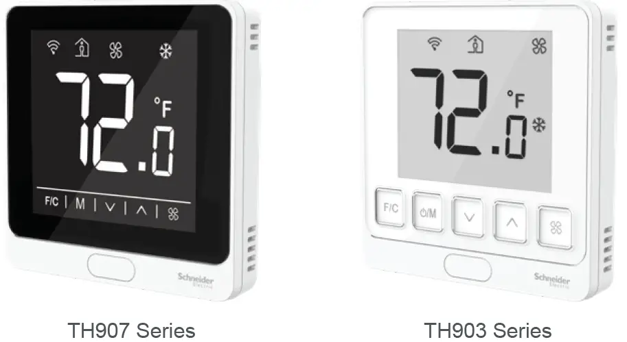
Product Description
The TH900 Series thermostats are optimized for office building, hotel and residential terminal HVAC control.The TH900 Series is ideal for PTAC, Fan Coil, Heat Pump and Gas/Oil Furnace applications.These models are available in two housing finishes: optimum (black glass display with capacitive buttons on a black or white base) or medium (white glass display with mechanical buttons on a white base).The TH900 Series is a wall surface mount device that is easy to operate. These thermostats feature microprocessor-based controls and large LCD screens which display operation status (cooling, heating and auto), fan speed, room temperature and set-point.
Specifications
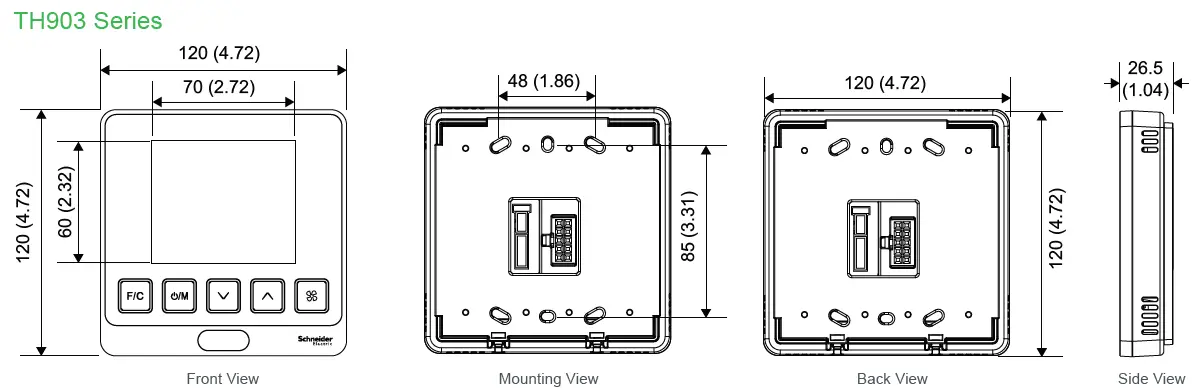
Heat stages 1 stageCool stages 1 stageSensing element Digital temperature sensorAccuracy ±0.5° to 50°C(±1° to 122°F)Set-point range 5 to 35°C (41 to 95°F)Display range 0 to 50°C (32 to 122°F)Display resolution 0.5°C (1°F)Operating temp. 0 to 50°C (32 to 122°F)Operating humidity 0 to 95 % RH (non-condensing)Storage temp. -20 to 60°C (-4 to 140°F)Storage humidity 0 to 90 % RH (non-condensing)PIR detection 120° (±60°)PIR detection distance 10m at 0°, 5m at 60°, 5m at -60°Power consumption Standby < 0.5WPower supply 24 VAC @ 50/60Hz or 24 VDCTerminal cable 14 AWG to 18 AWG solid or stranded wireLoad rating 3A resistive, 1A inductive, 1A pilot dutyProtection class IP 30Housing Flame-retardant PCDimensions 120 x 120 x 26.5mm(4.72 X 4.72 X 1.04 in.)Pollution degree Pollution Degree 2Operation type Type 1.BControl purpose Operating controlControl construction Independently mounted control for flush mountingImpulse voltage 330V
Regulatory Information
Agency approvals
- FCC CFR 47 Part 15 Subpart B Class B
- RSS 247
- ICES-003:issue 6
- UL 60730-1
- UL 60730-2-9
- CAN/CSA-E60730-1
- CAN/CSA-E60730-2-9
- European Conformance CE:
- IEC/EN 60730-1
- IEC/EN 60730-2-9
RoHS 2011/65/EUcompliance 2015/863/EU
REACH compliance 1907/2006/EC
Precautions
- This product is not intended for life or safety applications.
- Do not install this product in hazardous or classified locations.
- Read and understand the instructions before installing the product.
- Turn off all power supplying equipment before working on it.
- The installer is responsible for conformance to all applicable codes.
- External housing may be cleaned with a damp cloth if it becomes dirty. Do not use any cleaning agent, especially alcohol.
If this product is used in a manner not specified by the manufacturer, the protection provided by the product may be impaired. No responsibility is assumed by the manufacturer for any consequences arising out of the use of this material.
Dimensions mm (in.)

SpaceLogic Thermostat TH900 Series Installation Instructions
Installation
Location
Select a location about 1.5m (5ft.) above the floor with good air circulation at average temperature. Indoor use only. Do not mount thermostat where it may be affected by:
- Drafts or dead spots behind doors or in corners
- Hot or cold air from ducts
- Radiant heat from sun or appliances.
- Concealed pipes or chimneys
- Unheated (un-cooled) areas behind the thermostat
- If Zigbee equipped, do not install near other RF sources/ transmitters
- When the thermostat is equipped with PIR, consider view angle, range characteristics, and mounting position for proper coverage
Mounting
The HVAC thermostat is typically mounted on a standard double-gang (4 x 4) junction box. The installation kit provides a Smart Wall Mounting Plate.If mounted on a single-gang box, use the two central holes of the Smart Wall Mounting Plate. To mount the HVAC thermostat, complete the following steps:
- Position the Smart Wall Mounting Plate as shown in Figure 1.
- Ensure the Smart Mounting Plates are oriented to follow the marking that says “This side up”. Snap them together, ensuring all 4 corner snap hooks are attached, then attach them to the junction box using the supplied screws.
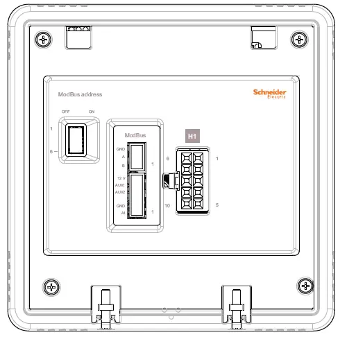
- Use wire nuts to connect the Power/HVAC and other low voltage signal wiring harness to the power and heat pump/valve/fan control signal wires within the electrical box. See the pre-defined commissioning document for application-specific wire connections.
- To connect the unit to the input power and the relays to the loads, plug the pre-wired power/HVAC and other signals harness connector into the female receptacle at the back of the unit (H1/H2/H3).
- Hook the tabs at the top rear of the unit housing into the matching depressions at the top of the Smart Mounting Plate and rotate the bottom of the housing toward the wall until it snaps into place.
- Secure the housing to the Smart Mounting Plate with the two small captive screws at the bottom of the housing.
- Apply power to the unit by closing the applicable supply breaker. After connecting power, OFF mode (factory default setting) will appear on the LCD display.

SpaceLogic Thermostat TH900 Series Installation Instructions
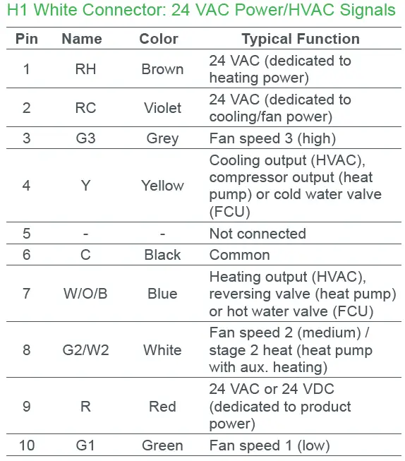
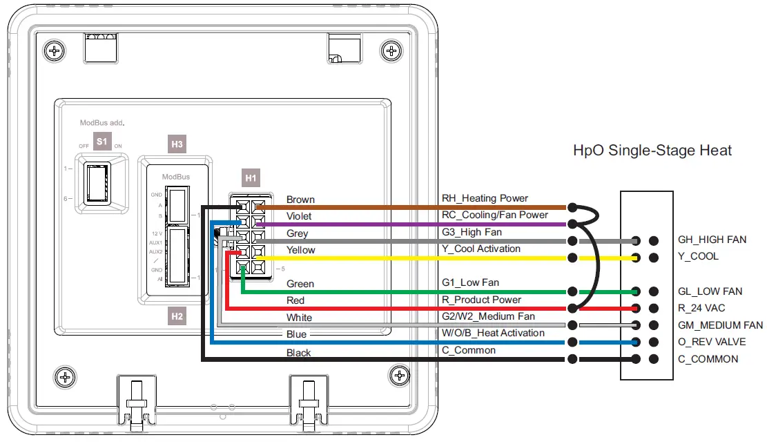
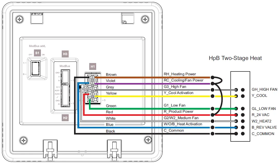
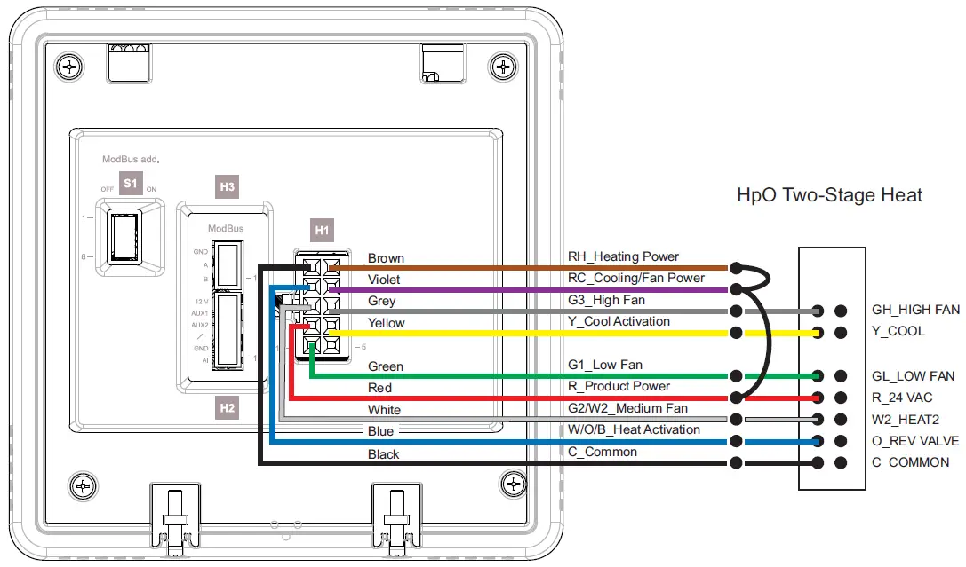
Wiring
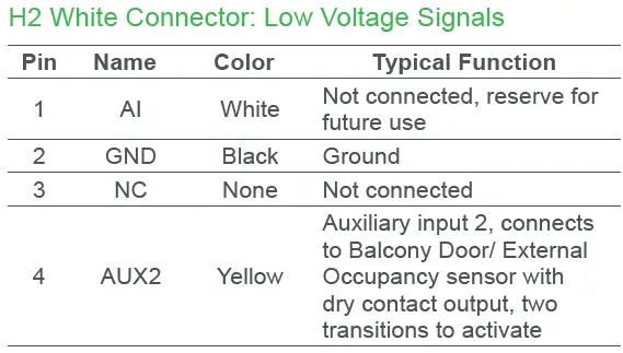
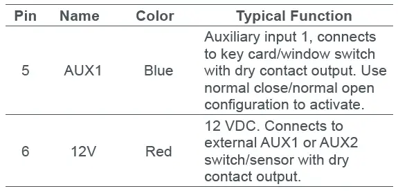

Wiring Diagrams
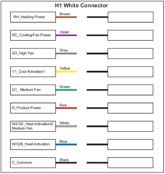
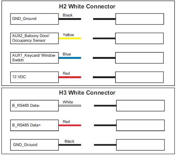
Note: Prior to beginning an installation, use the HVAC Wire Harness Templates at the end of this document to identify the wires/signals coming out of the 4×4 box and to determine which wires are connected to which wires on the thermostat. These templates provide a quick and easy ‘cheat sheet’ to capture property-specific wiring requirements.If you have technical questions, please contact the Schneider Electric Customer Care Center in your country (see schneider-electric.com/contact).
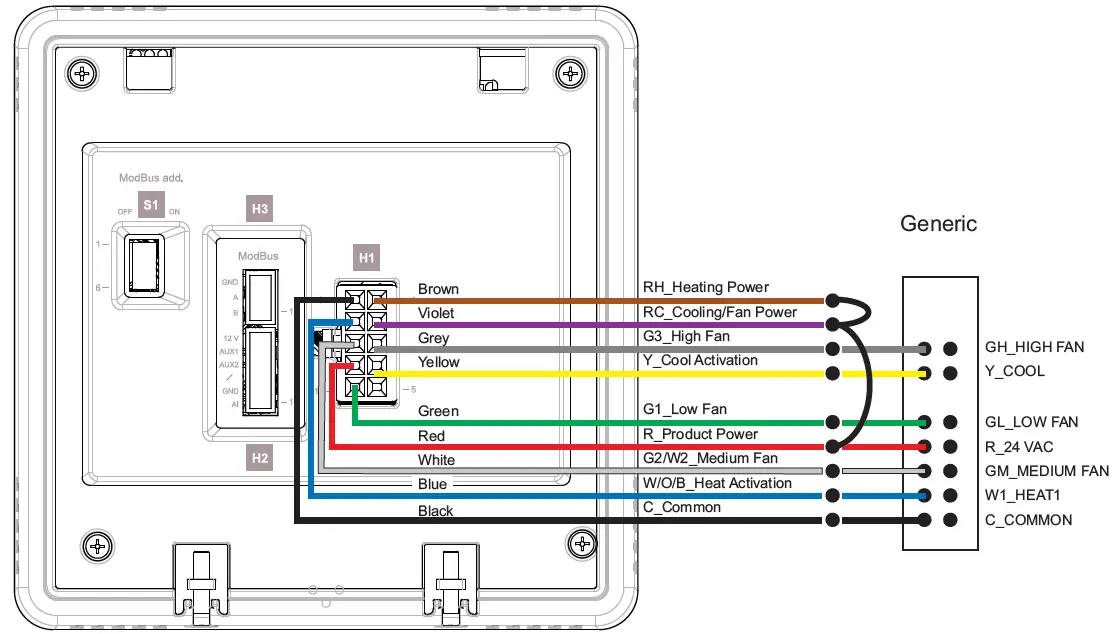
Generic FCU/Conventional HVAC: 24 VAC
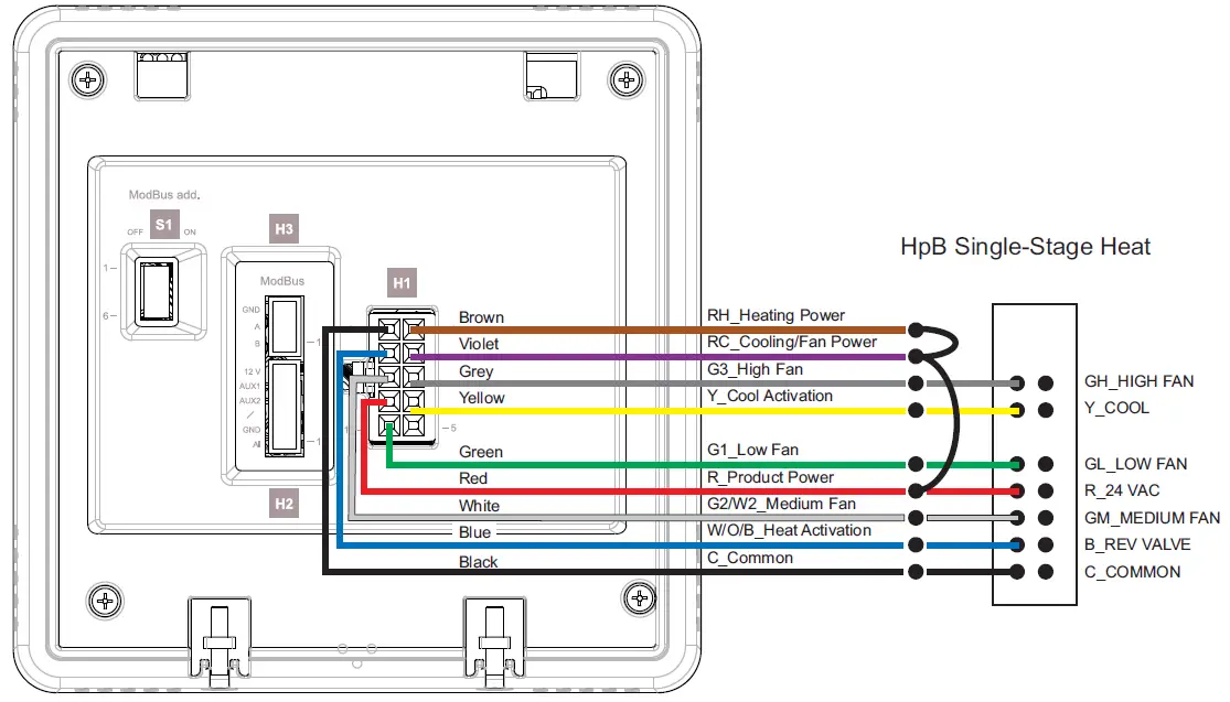
Heat Pump B (HpB) Single-Stage Heat: 24 VAC
Heat Pump O (HpO) Single-Stage Heat: 24 VAC
Heat Pump B (HpB) Two-Stage Heat:24 VAC
Heat Pump O (HpO) Two-Stage Heat: 24 VAC
Typical HVAC Applications

User Interface
User Setup Setting ModeWhen unit is OFF (but powered), long press and hold the FAN button for 15 seconds to enter the user setup setting table. See user guide for details.
Installer Setup Setting ModeWhen unit is OFF (but powered), long press and hold the F/C button for 15 seconds. Release the F/C button after the backlight flash. Press the UP button within three seconds to enter the installer setup setting table. See the user guide for details.
Protection ModeWhen Frost Protection and High Temperature Protection is enabled, the measured ambient temperature is continuously monitored to ensure it does not exceed the High Temperature Protection setpoint or fall below the Frost Protection setpoint. An LCD and alarm indication alerts the user that the temperature exceeds the upper or lower limit.See the user guide for details.
Normal Operation ModeWhen a button is pressed by the user, the device will display the system modes and the temperature. When the unit is not in use for more than 15 seconds, the LCD and button backlight will turn off or brightness will be minimized.
ECO ModeECO mode minimizes energy consumption when a room is unoccupied and the device is ON. It allows for quick resumption when people return to the room. When the room is unoccupied, the device reverts back to ECO mode.
Button Lock and Unlock ModeWhen the unit is ON, press and hold the button for 15 seconds. Release the button after the Lock icon flickers. Then press the UP button within three seconds to activiate the button lock. The Lock icon will appear on the LCD. When the button lock is activated, press and hold the button for 15 seconds. Release the button after the Lock icon flickers, then press the UP button within three seconds to deactivate the button lock. The Lock icon will disappear from the LCD.
Interface Navigation
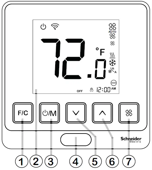
Normal Operation Mode
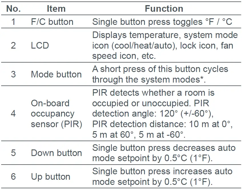
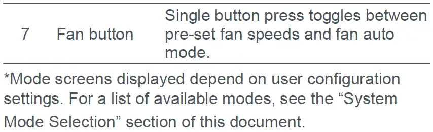
Setting the Fan SpeedA short press of the FAN button toggles between pre-set fan speeds and fan auto mode.
- AUTO – Fan operates in low, medium or high speed as needed (and can be disabled in configuration). Setting the fan to AUTO allows the blower to operate off and on intermittently in time with the heating or cooling system.
- FAN LOW – Fan operates in low speed.
- FAN MEDIUM – Fan operates in medium speed
- FAN HIGH – Fan operates in high speedA fan setting of ENABLE/DISABLE can also be set in the User Setup Settings menu.
- ENABLE – Fan blower continues to run after the system is turned off (OFF mode). Allows for manual switching of fan speeds (LOW/MEDIUM/ HIGH/OFF).
- DISABLE – Fan turns off after the system is turned off (OFF mode).
System Mode Selection
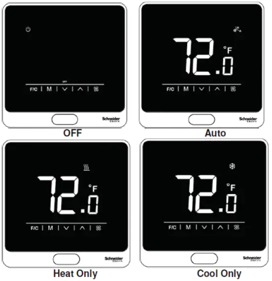
Touchscreen Models
Note: Default modes are OFF and Auto. Additional modes can be enabled by the user.
Note: Default modes are OFF and Auto. Additional modes can be enabled by the user.
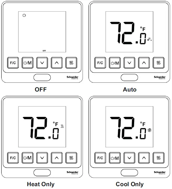
The default modes displayed by TH900 Series thermostats are OFF and Auto. Other available mode options include OFF/Auto/Heat/Cool, OFF/Heat Only and OFF/Cool Only. In order to access these modes, the user must first enable them within the Installer Setup Setting Mode settings.With a short press of the MODE button, the ther-mostat will cycle between OFF > Auto by default modes. In each of these modes, the contents of the display change accordingly. Note that Auto, Heat Only and Cool Only have identifying icons displayed above (touchscreen version) or to the left of the temperature (pushbutton version).
- In Auto mode, the measured ambient temperature is compared to the set point. Temperature control is achieved by setting the fan speed to automatic and engaging the heating or cooling valves.
- When the fan is operating under automatic control, the applicable fan on/off is chosen automatically based on the temperature difference necessary to achieve the air temperature set point.
- If the user selects the fan to run in low speed via the fan button, then temperature control is delegated to the heating control and cooling control. The fan is no longer modulated until the setpoint is changed (defaults back to Auto mode) or the M button is pressed.
During normal operation, the measured ambient temperature is continuously monitored to ensure it does not exceed the High Temperature Protection setpoint if High Temperature Protection is enabled. Similarly, the measured ambient temperature is monitored to ensure it does not fall below the Frost Protection setpoint if the Frost Protection configura-tion is enabled.
Protection Modes
The Frost Protection and High Temperature Protection modes can be enabled or disabled. When enabled, their setpoints are configurable, as described below.
- Frost Protection (low temperature) can be enabled or disabled. When enabled, its setpoint ranges from 5 to 15°C (41 to 59°F). Default is 5°C (41°F). If Frost Protection is enabled and the measured ambient temperature is lower than its Frost Protection limit, then even when the device is OFF, heating will turn on automatically, as indicated on the LCD. Heating will turn off when the ambient temperature reaches the setpoint + 2°C (4°F).
- High Temperature Protection can be enabled or disabled and its setpoint ranges from 25 to 35°C (77 to 95°F). The default is 35°C (95°F). If High Temperature Protection is enabled and the measured ambient temperature is higher than its setpoint limit, then even when the device is OFF, cooling will turn on automatically as indicated on the LCD. Cooling will turn OFF when the ambient temperature decreases to the High Temperature Protections setpoint minus 2°C (4°F).
If the low temperature exceeds the display range of 0°C (32°F), this will be indicated with ‘LO’ on the LCD.If the high temperature exceeds the display range 50°C (122°F), this will be indicated with ‘HI’ on the LCD.If the on-board temperature sensor is not operating correctly (if it is open or short), ‘Er’ will be displayed on the LCD.
HVAC Wire Harness TemplatesUse the wire harness templates below to note your wiring connections.
Regulatory Compliance
FCCThis device complies with part 15 of the FCC Rules. Operation is subject to the following two conditions: (1) This device may not cause harmful interference, and (2) this device must accept any interference received, including interference that may cause undesired operation.Note: This equipment has been tested and found to comply with the limits for a Class B digital device, pursuant to part 15 of the FCC Rules. These limits are designed to provide reasonable protection against harmful interference in a residential installation. This equipment generates, uses and can radiate radio frequency energy and, if not installed and used in accordance with the instructions, may cause harmful interference to radio communications. However, there is no guarantee that interference will not occur in a particular installation. If this equipment does cause harmful interference to radio or television reception, which can be determined by turning the equipment off and on, the user is encouraged to try to correct the interference by one or more of the following measures:
- Reorient or relocate the receiving antenna.
- Increase the separation between the equipment and receiver.
- Connect the equipment into an outlet on a circuit different from that to which the receiver is connected.
- Consult the dealer or an experienced radio/TV technician for help
Industry CanadaThis device complies with Industry Canada licence-exempt RSS standard(s) . Operation is sub-ject to the following two conditions: (1) this device may not cause interference, and (2) this device must accept any interference, including interference that may cause undesired operation of the device.Le présent appareil est conforme aux CNR d’In-dustrie Canada applicables aux appareils radio exempts de licence. L’exploitation est autorisée aux deux conditions suivantes : (1) l’appareil ne doit pas produire de brouillage, et (2) l’appareil doit accepter tout brouillage radioélectrique subi, même si le brouillage est susceptible d’en compromettre le fonctionnement.
WEEE Directive 2012/19/ECWaste Electrical and Electronic Equipment DirectiveDispose of this device separately from household waste at an official collection point. Professional recycling protects people and the environment against potential negative effects.
User Guide LinkUse the URL or QR code below to access the user guide for this product.https://iportal2.schneider-electric.com/
 report this ad
© 2020 Schneider Electric. All rights reserved. All trademarks are owned by Schneider Electric Industries SAS or its affiliated companies. Schneider Electric, 35 rue Joseph Monier, F – 92500 Rueil-Malmaison
References
Schneider Electric Global | Global Specialist in Energy Management and Automation
Our offices around the world
Login – Schneider Electric Buildings iPortal
Schneider Electric Global | Global Specialist in Energy Management and Automation
Schneider Electric Global | Global Specialist in Energy Management and Automation
Our offices around the world
Login – Schneider Electric Buildings iPortal
Schneider Electric Global | Global Specialist in Energy Management and Automation
[xyz-ips snippet=”download-snippet”]