ScreenBeam 1100Wireless Display ReceiverQuick Start Guide
This Quick Start Guide provides the instructions on how to install the ScreenBeam 1100 receiver, connect client devices, and set up for deployment.
Before Beginning Deployment
Before deploying ScreenBeam products, check for the latest firmware, release documentation, and tech tips.
- For ScreenBeam receiver’s deployment guide, firmware upgrades, and release notes go to: https://support.screenbeam.com/1100
- For Miracast™ or native macOS/iOS wireless display connection tutorial, go to: https://www.screenbeam.com/setup
- For ScreenBeam Central Management System (CMS) software, go to: https://support.screenbeam.com/cms
- For Open Source information, go to: http://opensource.screenbeam.com
Package Contents
- ScreenBeam 1100 receiver
- Quick Start Guide (this document)
- Power supply
- Regulatory documents
- HDMI cable
Introduction
The ScreenBeam 1100 allows presenters with Windows 10, macOS, iOS, or Android devices to wirelessly display without requiring any apps. ScreenBeam 1100 offers a variety of secured network modes to support connection from the internal users on different subnets and external guest users.
Overview of Network Modes
ScreenBeam 1100 supports local Wi-Fi, Wi-Fi Miracast, and wireless display over the existing infrastructure network. Two or more modes can operate concurrently to support various scenarios where both internal and guest users could simply connect and project.
DocumentationFor FAQs, troubleshooting tips, and support, visit: https://support.screenbeam.comNeed Help?To open a ticket for support, visit: https://support.screenbeam.com/ticket
Local Wi-Fi
The ScreenBeam Wi-Fi model provides the simplest form of network for client devices to connect and project. In this mode, the user needs to connect the client device Wi-Fi to the ScreenBeam Wi-Fi and then select the receiver to mirror. This mode is ideal for guest clientdevices that need wireless display and or Internet access. Internet is available if the ScreenBeam receiver is connected to the existing network, wired or wireless if bridge mode is enabled. Mobile devices with cellular service can access the Internet and wireless display if bridge mode is disabled.
Figure 1 Client device wireless display by connecting to ScreenBeam’s local Wi-FiNote: ScreenBeam Wi-Fi is fully secured and manageable via ScreenBeam CMS with options to tune the wireless power transmission, channel, and encryption type.
Wi-Fi Miracast
The Wi-Fi Miracast mode allows compatible Wi-Fi Miracast devices to connect directly to ScreenBeam, even when connected to an infrastructure wireless network. Miracast is commonly available on Windows 10/8.1 and Android 4.4 (and later) devices since 2015.Users can enjoy the wireless display and Internet access if the client device is already connected to Wi-Fi.
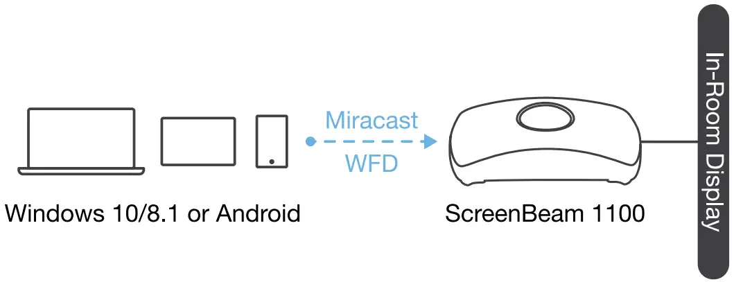
Figure 2 Miracast client device wireless display by connecting to ScreenBeam’s Wi-Fi Miracast network
Wireless Display over existing LAN
ScreenBeam 1100 can be connected to the existing wireless or wired network and supports wireless display for client devices on either network. This is a common setup to support client devices that needs access to network resources. Additional port and network configurations may be required for this model to work seamlessly.
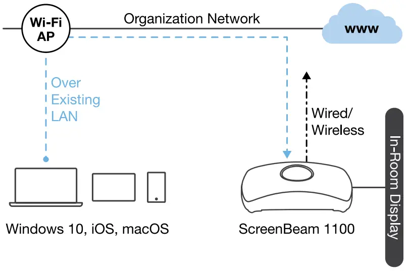
Figure 3 Client device wireless display over the existing infrastructure networkScreenBeam 1100 can be connected to two different networks concurrently. This dual-network feature allows the flexibility of supporting wireless display for either staff (on the internal network) or visitors (on the guest network). Refer to the deployment guide for more details.
Minimum Requirements
System RequirementsClient devise from 2015 or newer with one of the following operating systems:
- Windows 10 build 1709 (and later)
- macOS X 10.10 (and later)
- iOS 11 (and later)
- Android 4.4 (and later) with Miracast
Network RequirementsFor wireless display over the existing wireless network or LAN:
- Ethernet: 100BASE-T 10/100 connection (1 Gbps is recommended)
- Wireless: 802.11ac (5GHz is strongly recommended)
- Multicast DNS (mDNS) support is required for iOS and macOS native screen mirroring to auto-discover ScreenBeam
- Required ports
- 5353 (UDP) for Multicast DNS (mDNS) discovery
- 7100 (TCP and UDP) for macOS, iOS, and Windows 10 mirroring
- 7250 (TCP) for Miracast over LAN data stream
- 18000-18009 (TCP) for macOS and iOS AV data
Note: Additional network configuration is not required for Wi-Fi Miracast enabled device to connect. Verify Group Policy and firewall settings to allow Wi-Fi Direct groups or hosted networks.
Setup Requirements
- ScreenBeam 1100 receiver
- Display with an available HDMI input
- (Optional) Touchscreen with USB touch cable
- An ethernet network connection with DHCP IP or a Wi-Fi router
Note: This is used for wireless display over LAN and management.
- ScreenBeam wireless display app
Note: Not required for Windows 10/8.1, macOS, and iOS with native screen mirroring support.
A. Setting up ScreenBeam 1100 Receiver
Figure 4 ScreenBeam 1100 setup
- Place the receiver next to the display.
- Connect one end of the provided HDMI cable to the receiver’s HDMI port and the other end to an available HDMI port on the display.Note: For VGA connection details, refer to the ScreenBeam 1100 User Guide.
- Optional: If the display has USB HID touch capability, insert the HID USB connector into a USB port of the ScreenBeam receiver. (USB cable is not included)
- Connect the receiver’s power supply to the receiver’s power port, then to an electrical outlet.
- Optional: Connect one end of the Ethernet cable to the receiver’s Ethernet port and connect the other end to the network switch with DHCP IP. (Ethernet cable is not included).Note: Refer to section B for more information on setting up a network connection.
- Turn on the display and switch to the corresponding input connected to the receiver.
- Wait for the Ready to Connect screen to appear on the display.
B. Set Up Network Connection
ScreenBeam requires a network connection for various purposes, such as wireless display over LAN support and management of the receiver. ScreenBeam can be connected to the network via a wired or Wi-Fi connection.
Wired ConnectionIf ScreenBeam is connected to a DHCP-enabled network, the Ready to Connect screen will show the IP address assigned to the ScreenBeam.
Wireless Connection or Static IP AddressThis requires additional steps to configure the receiver with the proper network credentials. Refer to Section D for instructions on how to set up the ScreenBeam receiver.Using a wired connection with DHCP IP is recommended for initial testing.
C. Connect Client Device
This section provides instructions on how to connect to ScreenBeam using the native screen mirroring from the most common operating systems.Refer to www.screenbeam.com/setup for details and instructions for all other operating systems.Note: The web page will display the instructions based on the client-device OS. Use the links at the bottom of the web page to select OS-specific instructions.
Connect Using Local Wi-Fi
- Connect the client device’s Wi-Fi to the wireless network (AP SSID) as shown on the TV display. Windows 10/8.1 or Android with Miracast can skip to Connect Using Wi-Fi Miracast section.
- Enter the password for the wireless network. screen beam is the default password.
- Select the ScreenBeam receiver name as shown on the TV display.• For Windows 10Select Connect from the Action Center by swiping from right or simultaneously pressing the Windows key and K.• For iOS or macOSConnect with
 from the menu bar or control center.
 - Enter in the PIN if required. If the PIN code is not displayed, try the hidden PIN 1234.
- Select duplicate or extended screen mode if prompted.
- If the display has touch functionality, Windows 10 devices can take advantage of the touch and inking feature by selecting Allow touch…. (Refer to section F for more details.)Note: To disconnect, return to the screen mirroring menu and select mirroring off.
Connect Using Wi-Fi Miracast
- Select the ScreenBeam receiver name as shown on the TV display.• For Windows 10Select Connect from the Action Center by swiping from right or simultaneously pressing the Windows key and K.• For AndroidSelect the Screen Mirroring option from the quick access menu and follow the connection instructions.
- Enter in the PIN if required. If the PIN code is not displayed, try the hidden PIN 1234.
- Select duplicate or extended screen mode if prompted.
- If the display has touch functionality, Windows 10 devices can take advantage of the touch and inking feature by selecting Allow touch…. (Refer to section F for more details.)
Note: Some Android devices do not support PIN and will fail to connect. Refer to section D below for instructions on how to configure ScreenBeam and disable PIN enforcement.
Connect Using theExisting Wireless Network or LAN
- Connect the ScreenBeam receiver to a known network where your client device can communicate over Wi-Fi.
- Verify the receiver obtained an IP address (shown on the Ready to Connect screen).
- Connect the client device to the same network as the ScreenBeam receiver
- Select the ScreenBeam receiver name as shown on the TV display.• For Windows 10Select Connect from the Action Center by swiping from right or simultaneously pressing the Windows key and K.• For iOS or macOSConnect with from the menu bar or control center.
- Enter in the PIN if required. If the PIN code is not displayed, try the hidden PIN 1234.
- Select duplicate or extended screen mode if prompted.
- If the display has touch functionality, Windows 10 devices can take advantage of the touch and inking feature by selecting Allow touch…. (Refer to section F for more details.)
Congratulations!The display is now enabled for wireless screen mirroring.
D. Configure ScreenBeam Receiver
ScreenBeam 1100 can be configured by using the ScreenBeam CMS software or accessing the ScreenBeam’s local management interface (LMI).
Using ScreenBeam CMS SoftwareScreenBeam Central Management System (CMS) is a highly recommended complementary tool for multi-unit deployment, configuration, and administration.
- To obtain CMS software and the CMS User Guide, go to: https://support.screenbeam.com/cms.
- Refer to the CMS User Guide for setup instructions.
Note: Access to the LMI is prohibited by default if ScreenBeam 1100 is connected to ScreenBeam CMS for management. This option can be changed in the receiver’s settings.
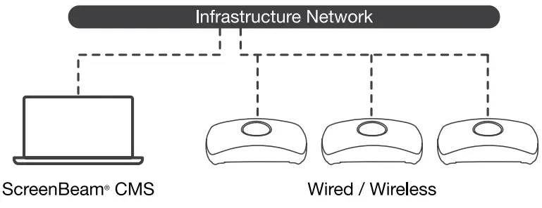
Figure 5 Receivers managed by ScreenBeam CMS
Using Local Management on ScreenBeamThe Local Management Interface can configure and update a single ScreenBeam. There are three methods to access the LMI:
Method 1: ScreenBeam Local Wi-Fi Network
- Connect the client device’s Wi-Fi to the wireless network (AP SSID) as shown on the TV display.
- Enter the password for the wireless network. screen beam is the default password.
- The Ready to Connect screen on the display will show the assigned IP address of the ScreenBeam.
- Enter the assigned IP address into the web browser of a PC or Apple device.• If the receiver is not connected to an existing wireless network or LAN, its IP address is 192.168.26.1.• If the receiver is connected to a network, the IP address can be identified on the Ready to Connect screen.
- The browser may give an error stating “The connection or site is not secure or private.” Manually accept the connection as follows:Chrome browser: click Advanced, then click Proceed.Edge/IE browser: click Details, then Go on to the webpage (not recommended).Firefox browser: click Advanced, then click Add Exception, then click Confirm Security Exception.
- When the ScreenBeam management page appears, enter the Username Administrator and Password screen beam (both case-sensitive).
Method 2: Network Connection via DHCP
- Using a shielded RJ-45-terminated Cat5e or better Ethernet cable, connect the ScreenBeam Ethernet port to a DHCP-enabled network.
- The Ready to Connect screen on the display will show the assigned IP address of the ScreenBeam. Enter this address into the web browser of a PC or Apple device on the same network as the ScreenBeam.
- Follow the directions from Method 1 from Step 5 on.
Method 3: Wireless P2P Direct Connection
- Using a Windows 10/8.1 device, connect the device to the ScreenBeam per section B above.
- Once connected, use a web browser and enter https://192.168.16.1 to access the LMI.
- Follow the directions from Method 1 from Step 5 on.
E. Customize ScreenBeam Settings
Under the Device Configuration PageAssign new Device Name
- From the Device Name Access option, select Enable.
- Select the Device Name text box, then enter a new name (example: Conference TV).
Note: Each receiver should have a unique name; this makes it easier for users to identify and connect to the correct display.Supported naming characters areA-Z, a-z, 0-9, -, _.
Change the Administrator’s Password
- Select the Administrator Password text box and enter the new password.
- Select Apply/Save button to save any changes.
Under the Features Page
Configure Force PIN Pairing Option
By default, the Force PIN Pairing option is Enabled and the PIN code is generated randomly. A unique PIN is will be generated each time a new user/device attempts to connect. To change the PIN pairing type or PIN code:
- Select either ON to force PIN or OFF to not force PIN upon connection.
- If Force PIN Pairing is ON, select either Each connection or First connection only.
- Select Random or Static for PIN code generation.
- If Static, then enter the PIN of choice. Keep note of the new PIN for user distribution.Note: For the eight-digit PIN option, only the first seven digits of the PIN can be set in configuration; the eighth digit will be automatically chosen by the ScreenBeam and appended to the first seven.
- Select Apply/Save button to save any changes.
Configure HDMI/VGA PortPower ManagementBy default, ScreenBeam is designed to display the Ready to Connect screen continuously. To extend display life and/or reduce power consumption:
- Select either Screen Saver or Display Off.
- Enter the desired time for the setting to take effect.
- Optional: Select a Wake up mode.
- Select Apply/Save button to save any changes.
F. Using Interactive Touch Display
ScreenBeam 1100 supports wireless inking and touch with Windows 10 Miracast for collaboration using a touchscreen display. Users can project their preferred Windows 10 application and take notes on the touchscreen; the notes appear directly on the client device.
System RequirementsOS: Windows 10 build version 1709 (or later)CPU: 5th Gen Intel Core i-Series 5xxx or AMD equivalent (or better)RAM: 4 GB or more
Setup Requirements
- Interactive touch display or projector
- USB Type-A to Type-B/A cable (depending on the touchscreen type)
Supported Features
- Support USB HID display, projector, or whiteboard
- Up to 20-point touch
- Up to four simultaneous passive pens
- Up to two simultaneous active pens
Supported features may require a compatible touchscreen and or application. Works best with InGlass™ Technology enabled display.Refer to the online compatibility list at:https://support.screenbeam.com/touch/compatibility
Setup and Instructions
- Connect the USB Type-A end to the ScreenBeam 1100 receiver’s USB port.
- Connect the USB Type-B/A end to the USB Touch input on the display or projector.Note: If the display provides more than one touch output, make sure the USB Type-B/A end is connected to the same touch output as the HDMI input.
- Connect Windows 10 device to ScreenBeam 1100 (see instructions in section C).
- Start using the display by touching the screen. Launch an app and draw using a finger or pen.
G. Deploying ScreenBeam Receiver
Please read the deployment guide for best practices and tips before placing the ScreenBeam 1100 to the site for users.
- Unplug the power supply and HDMI cable from ScreenBeam 1100 receiver.
- Move the receiver to its permanent location.Note: Access to a wired or wireless LAN connection is required.
- Plug the HDMI cable into the receiver and the display.
- Plugin the receiver’s power supply.
- Switch the display to the correct input and verify the Ready to Connect screen appears.
- Verify the ScreenBeam 1100 obtains a valid IP address.
Note: By default, ScreenBeam shows all of the receiver’s information on the screen for ease of troubleshooting. The information can be configured to be hidden from the management interface or via CMS.
H. Expectations and Known Issues
- Wi-Fi Internet is limited when connecting to ScreenBeam local Wi-Fi unless ScreenBeam is connected to the network and bridge mode is enabled.
- If ScreenBeam is connected to the existing network, some existing access points and or controllers (i.e. Meraki or Cisco) may flag it as a rogue AP and restrict the client from connecting.Consult with the network administrator to flag ScreenBeam as a friendly access point.
- Windows 10 build 1803 (and earlier) does not support wireless display PIN on Miracast over LAN. The connection will fall back to establishing the Miracast over Wi-Fi Direct path.
Support Information
report this adFor FAQs, troubleshooting tips and support, visit: https://support.screenbeam.comTo open a ticket for support, visit: https://support.screenbeam.com/ticketWebsite: www.screenbeam.com
This product is intended to be supplied by a Listed Direct Plug-In Power Unit marked “Class 2”, Listed Power Adapter or DC power source marked “L.P.S.” (or “Limited Power Source”) and rated 12Vdc, 3A minimum.US SKU: Model # CDS036-W120U.International SKU: Model # ATS036T-W120V.Made by ScreenBeam.
PN: 0530-0838-002© 2020 All rights reserved. ScreenBeam and the ScreenBeam logo are registered trademarks owned by ScreenBeam Inc. All other names are properties of their respective owners. Specifications are subject to change without notice. 0406200-v8
References
[xyz-ips snippet=”download-snippet”]