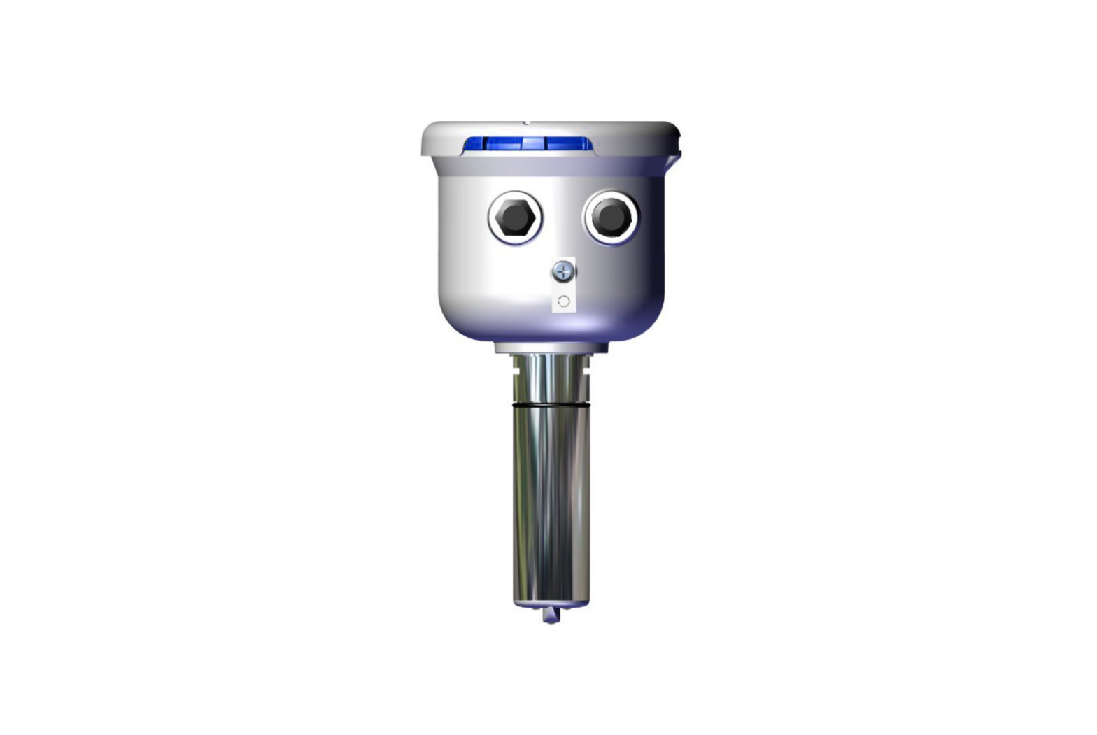
Seametrics EX90 Battery Powered Insertion Magmeter

Check Components
|
|
|
|
|
|
|
|
Optional |
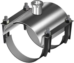 Saddle Assembly(Packaged Separately)
 U-clip Retainer
 Saddle Gasket
 Cable Gland
 Power/Output Cable
Recommended Tools
Recommended:
- 3/32″ or 2.5mm (small) flat head screw driver
- Crescent Wrench · 5/32″ Hex Key
Optional:
- Channel locks
- 6″ Strap Wrench
Warnings
Refer to instruction manual for further details.
- Confirm that U-clip retainer is installed and never remove the U-clip retainer when pipe is under pressure–may result in serious injury.
- Saddle bolts must be tightened evenly. Do not over tighten.
- Install security seal during installation if regulations require.
- Improper sealing of cables or cable glands will void warranty.
- Ensure proper grounding when required.
- Programming pipe ID, pipe insertion hole size and straight pipe configuration is required for the meter to read.
Positioning
Choose a position that will ensure a full pipe.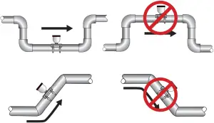 Choose a position that will minimize flow distortion.
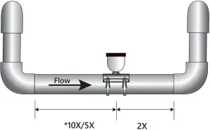 Upstream straight pipe is selected during initial setup. Upstream options are 5X or 10X the diameter and are based on the amount of straight pipe available in either new or propeller meter replacement installation. Downstream straight pipe requirement is 2X the diameter. See programming setup for details.
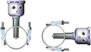 Side (3 o’clock) and top (12 o’clock) installations are acceptable.
BEFORE INSTALLING measure & record inside diameter (ID) of pipe.
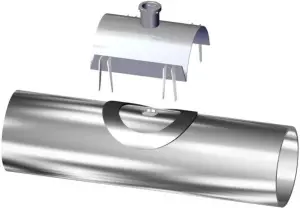
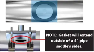
- Clean the mounting surface, remove any roughness from the area and cut a 1.75″ hole into pipe. Place gasket centered over pipe opening.

- Place saddle top over gasket.
- Make sure saddle top covers entire gasket.
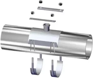
- Place the saddle clamps under the pipe and align with the clamp guides on the saddle top.
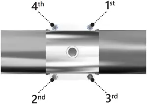
- Place saddle plates over saddle clamp threads. Attach nuts and tighten as shown below. Torque to 75 ft-lb in cross pattern.
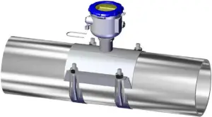
- Insert the EX90 sensor into the saddle fitting and secure with mounting clip or attach security clip and seals if required.

Wiring
Unscrew the display lid and remove it from the meter. Unsnap the display assembly and remove it from the meter exposing the internal wiring connector. Install the wires through the cable glands into the 2 pin screw connector.(C1 = power/output cable)
With Pulse Output Only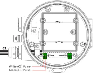
Pulse with External DC Power Source9 – 36 VDC at 250mA max, 30mA average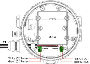
With No External Output – If not using external output, no wiring is required.
EXTERNAL POWER WARNING!Ribbon cable must be connected BEFORE external power is applied. See Instruction manual for details.
 WARNING: Improper sealing of glands or cables will invalidate any warranty. If plugs or cable glands are removed, reinstall using Teflon pipe sealant, or tape, to ensure maximum moisture protection.
Remove plug & o-ring. Insert cable gland/strain relief. Feed cable through cable gland.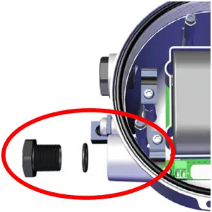 Clamp cable with strain relief clips. Attach drain wire lug to bracket post.
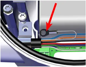 Torque cable gland sealing nut to 22 in-lbs.
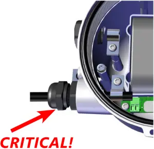
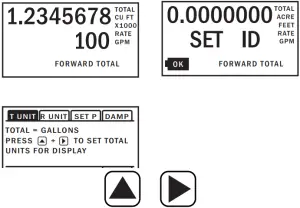 The HOME Screen displays flow volume, direction of the flow total and flow RATE along with status conditions such as Empty Pipe. Two buttons below the LCD display are used to access menu screens for viewing and changing meter setup parameters.
These two buttons are light sensors which can detect when a finger is covering them and activate upon release. Only three button touch actions are needed to control navigation through the menus, settings changes and back to the home screen.
HORIZONTAL SCROLLING: Tap right-hand button to scroll horizontally through menu tabs or move horizontally within a tab dialog when applicable.
SELECT: Tap left-hand button to change a highlighted item within a tab dialog.
ENTER/EXIT: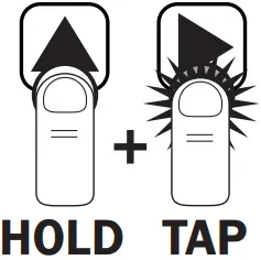 Hold left button while tapping right button once to enter or exit a tab dialog or to navigate between the HOME and other menu screens.
All menu screens consist of two rows of tabs surrounding a dialog box that lets you view and change setup parameters. To enter the Menu System perform the hold and tap sequence.
Changing Settings
HOME SCREEN The Home Screen page on a new meter will indicate for you to SET ID. to move to the Passcode Screen.
PASSCODE Set passcode if required, or to move to the Standard Menu Options Screen.
T UNIT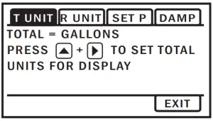 View or change TOTAL volume units
R UNIT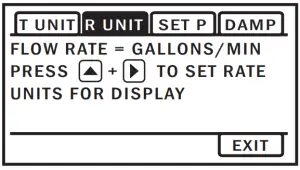 View or change flow RATE units
SET P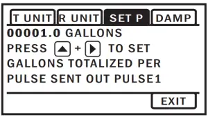 View or change pulse output scaling
DAMP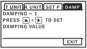 View or change # of sample periods for rolling average* DAMP default set to 15
EXIT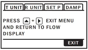 Return to HOME SCREEN or Tap
 ![]() five times, to enter a SUBMENU screen from which you can access the required pipe setting functions
five times, to enter a SUBMENU screen from which you can access the required pipe setting functions
Enter Pipe Settings (Required)
INITIAL SETUP OF ID, HOLE, AND PIPE IS REQUIRED FOR THE METER TO OPERATE PROPERLY.
- SETUPView or change meter configuration settings.
- SETUP (Menu Functionality)The highlighted value can be changed using the arrows. The value on the left is the menu name. Cycle through these by pressing . Press to highlight and change the value of the menus.
- ID (Required)View or change inner diameter of the pipe. Measurement in inches.
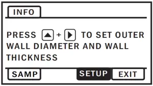
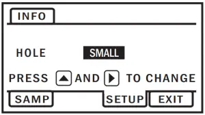
- HOLE (Required)View or change installation pipe hole size. Tap then to change setting from N/A (default) to small and large sizes.Note: See instruction manual page 14 for hole size description.
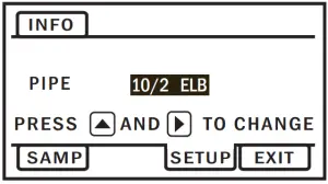
- PIPE (Required)View or change pipe configuration based on installation. Tap then to change setting from N/A (default) to 10/2, 5/2 or STRAIGHT (conditions with 10 diameters or more)
 View or change meter configuration settings.
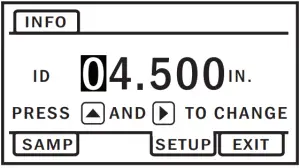
INFO: Meter model, serial number, firmware version
SAMP: Sample rate (Default is set to 5 seconds. Battery life with a 5-second sampling rate is four years. Increase sampling interval to extend battery life. (May vary depending on environmental factors. See instruction manual for more details.)
Seametrics19026 72nd Avenue South Kent, Washington 98032USA (P) 253.872.0284(F) 253.872.02851.800.975.8153www.seametrics.com
 report this ad
References
[xyz-ips snippet=”download-snippet”]