
ENFORCER 917MHz HL-Series RF Receivers Installation Manual
HL-951R1-SQ shown
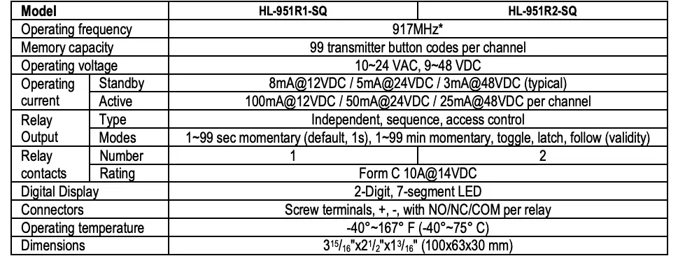
- Flexible operating voltage: 10~24 VAC, 9~48 VDC
- Independently programmable channels
- Compatible with all SECO-LARM HL-Series transmitters of the same frequency
- 5 Output modes per channel
- RF Signal strength / site survey test mode
One- and Two-Channel Receivers
*868.35MHz ![]() versions also available
versions also available
Compatible Transmitters
HL-951T1-SQ 1-Button pocket-sized pendant, 917MHz*, CR-2032 coin-type battery
HL-951T2-SQ 2-Button pocket-sized pendant, 917MHz*, CR-2032 coin-type battery
*868.35MHz ![]() versions also available
versions also available

HL-951T1-SQ shown
Introduction
The ENFORCER 917MHz HL-951 series RF transmitters and receivers use digital modulation for improved immunity to interference, better signal penetration in environments with heavy obstructions, and significantly longer range of up to 1,800ft (550m) line of sight. The transmitter’s ultra-low power consumption gives you longer battery life with easy to obtain coin-type batteries (CR-2032).
NOTE: Operating range will vary greatly depending on the installation and operating environment.
Installation Notes
Mount the receiver out of sight in a location where it is not exposed to weather or moisture. For optimal range, mount as high as possible and away from other electronic devices that might interfere with the signal
Entering Programming Mode
- . Press the selector button for 3 seconds or more. The channel’s LED will flash L1, indicating channel 1. Press the selector to toggle between channels 1 and 2.
- After 2 seconds, the LED will slow flash with the display showing the number of codes already in storage and enter programming mode.NOTE: The LED will flash a maximum of 15 seconds. If the selector button or no transmitter button is pressed during this time, the receiver will exit programming mode, and the LED will turn off.
- Enter programming mode and select the desired channel as described on pg. 1.
- While the LED is flashing, press the desired transmitter button to be learned one time. The three horizontal bars of the receiver’s LED indicator will flash two times to indicate the transmitter button has been successfully learned and will automatically exit learning mode. To learn further codes, re-enter programming mode and repeat.
NOTES:
- Do not press the selection button again after entering programming mode as this will take you to output mode programming.
- The indicator LED will flash a maximum of 15 seconds. If no transmitter button is pressed during this time, the receiver will exit code programming mode, and the LED will turn off.
- If the code has already been learned, the indicator LED will slowly flash two dashes. The code will not be learned a second time.
- One channel can learn the codes of a maximum of 99 transmitter buttons. If you attempt to learn an additional transmitter code, the earliest code learned will be deleted and the new code will be learned.
Clear Channel Memory
- Enter programming mode and select the desired channel to clear as described on pg. 1.
- While the LED is flashing the correct channel, press the selector button again for at least 3 seconds or until the channel indicator LED flashes 2 times. This will clear all codes for that channel.
- To clear codes from the other channel, enter programming mode for the other channel and repeat the above steps.
Display Channel Memory
- To see how many codes have been learned by a channel, enter programming mode and select the desired channel as described on pg. 1.
- The LED will flash for 15 seconds showing number of codes stored in that channel’s memory.
Programming Channel Relay Output Mode
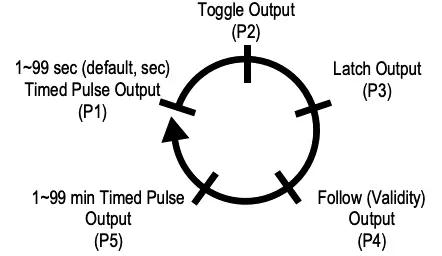
Each channel relay can be programmed to one of five output modes. (HL-951R2-SQ only: Each channel can be independently programmed to operate in a different output mode, depending on the user’s application.) The five modes are:
- P1 – 1~99 Second Timed Pulse Output (default, 1 second) – When the transmitter button is pressed, the relay will turn ON for the programmed number of seconds.
- P2 – Toggle Output – Works much like a toggle switch to turn a device ON & OFF alternately. Press the transmitter button once, and the relay turns ON. Press the transmitter button again, and the relay turns OFF.
- P3 – Latch Output – Press the transmitter button once, and the relay turns ON and stays ON. The channel relay will remain ON regardless of whether a compatible transmitter button is pressed again or not. To turn the relay OFF, press the selector switch on the receiver once to reset.
- P4 – Follow (Validity) Output – The relay status follows the transmitter button status and will remain active for as long as the transmitter button is pressed.NOTE: Due to possible interference or drops in transmitter battery power while the transmitter button is continuously pressed (even for short periods of time), the receiver may lose the transmitter’s signal and turn the relay OFF.
- P5 – 1~99 Minute Timed Pulse Output – When the transmitter button is pressed, the relay will turn ON for the number of minutes preset.
Selecting the relay output mode:
NOTE: For a diagram of the PC board, including the location of the function switch, please see Overview, pg. 3.
- Enter programming mode and select the desired channel as described on pg. 1.
- Press the selection button again. The LED will display the current output mode (default P1).
- To change a channel’s output mode, press the selector button repeatedly to scroll through the 5 output modes until the desire mode appears. Each press moves to the next mode in the sequence as shown in the diagram to the right.
- In modes P1 and P5, long press the selector button to choose the number of seconds or minutes, respectively
- When complete, wait 15 seconds for the receiver to automatically exit programming mode.
Overview
The LED indicator displays:
- General status – the left dot will flash every 3~5 when operating
- RF signal received – the right dot will light when an RF signal is being received
- TX Code enrollment and deletion
- Display number of codes programmed
- Output mode programming
See “LED Indicator” below for details.
HL-951R2-SQ PC board shown. Remove the front cover of the receiver to access the function switch and terminal block.
LED Indicator
Sample Applications

Specifications
*868.35MHz ![]() versions also available
versions also available
California Proposition 65 Warning: These products may contain chemicals which are known to the State of California to cause cancer and birth defects or other reproductive harm. For more information, go to www.P65Warnings.ca.gov.
FCC COMPLIANCE STATEMENTFCC ID: K4E951T4
THIS DEVICE COMPLIES WITH PART 15 OF THE FCC RULES. OPERATION IS SUBJECT TO THE FOLLOWING TWO CONDITIONS: (1) THIS DEVICE MAY NOT CAUSE HARMFUL INTERFERENCE AND (2) THIS DEVICE MUST ACCEPT ANY INTERFERENCE RECEIVED, INCLUDING INTERFERENCE THAT MAY CAUSE UNDESIRED OPERATION.
Notice: The changes or modifications not expressly approved by the party responsible for compliance could void the user’s authority to operate the equipment.
IMPORTANT NOTE: To comply with the FCC RF exposure compliance requirements, no change to the antenna or the device is permitted. Any change to the antenna or the device could result in the device exceeding the RF exposure requirements and void user’s authority to operate the device.
WARRANTY: This SECO-LARM product is warranted against defects in material and workmanship while used in normal service for one (1) year from the date of sale to the original customer. SECO-LARM’s obligation is limited to the repair or replacement of any defective part if the unit is returned, transportation prepaid, to SECO-LARM. This Warranty is void if damage is caused by or attributed to acts of God, physical or electrical misuse or abuse, neglect, repair or alteration, improper or abnormal usage, or faulty installation, or if for any other reason SECO-LARM determines that such equipment is not operating properly as a result of causes other than defects in material and workmanship. The sole obligation of SECO-LARM and the purchaser’s exclusive remedy, shall be limited to the replacement or repair only, at SECO-LARM’s option. In no event shall SECO-LARM be liable for any special, collateral, incidental, or consequential personal or property damage of any kind to the purchaser or anyone else.
NOTICE: The SECO-LARM policy is one of continual development and improvement. For that reason, SECO-LARM reserves the right to change specifications without notice. SECO LARM is also not responsible for misprints. All trademarks are the property of SECO-LARM U.S.A., Inc. or their respective owners. Copyright © 2021 SECO-LARM U.S.A., Inc. All rights reserved.
SECO-LARM® U.S.A., Inc.
16842 Millikan Avenue, Irvine, CA 92606Phone: (949) 261-2999 | (800) 662-0800
 report this ad
Website: www.seco-larm.comEmail: [email protected]
References
[xyz-ips snippet=”download-snippet”]