![]() SIR 020 / SIR 021 / SIR 022Countdown Timer
SIR 020 / SIR 021 / SIR 022Countdown Timer
 Installation and User Instructions
SIR 020 / SIR 021 / SIR 022The SIR range of countdown timers can be used to control immersion elements and other electrical appliances up to 3kW or as an override/extension timer for central heating systems.INSTALLATION AND CONNECTION SHOULD ONLY BE CARRIED OUT BY A SUITABLY QUALIFIED PERSON AND IN ACCORDANCE WITH THE CURRENT EDITION OF THE IET WIRING REGULATIONS.WARNING: ISOLATE MAINS SUPPLY BEFORE COMMENCING INSTALLATION AND ENSURE THE UNIT IS PROPERLY EARTHED.
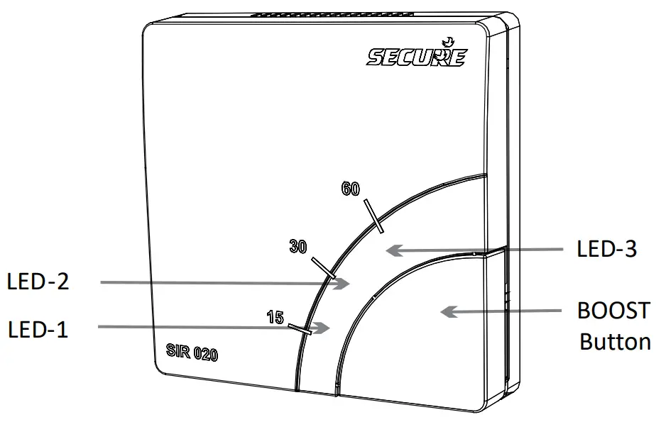 The LEDs become operational when the unit is powered up.
User instructions
To operate the unit press the BOOST button repeatedly until the indicator light for the required BOOST period is illuminated (see table below).
| Model | 1st-time buttonpress | 2nd-time buttonpress | 3rd time buttonpress | 4th-time buttonpress |
| SIR 020 | 15 min | 30 min | 60 min | off |
| SIR 021 | ½ hour | 1 hour | 2 hour | off |
| SIR 022 | 2 hour | 4 hour | 6 hour | off |
When BOOST is active the indicator lights count down, showing the duration of the BOOST period remaining.
| Model | LED – 1 on | LED – 1 & 2 on | LED – 1, 2 & 3 on |
| SIR 020 | 5min to 15min left | 16min to 30min left | 31min to 60min left |
| SIR 021 | 5min to 30min left | 31min to 60min left | 61min to 120min left |
| SIR 022 | 5min to 2hour left | 2hour 1min to 4hour left | 4hour 1min to 6hour left |
For all three models, LED-1 will flash slowly when 5 minutes of the boost period remains and will flash faster when 1 minute remains. At the end of the boost period, SIR will automatically switch off the connected appliance.The appliance can be switched off by canceling the boost period, using any of the following methods:
- If the BOOST button has just been pressed, wait for three seconds and then press it again. The indicator lights should all turn OFF.
- Press the BOOST button repeatedly, until ALL the indicator lights have turned OFF.
- Press and hold in the BOOST button until ALL the indicator lights have turned OFF.
Installation
A means of disconnection from the supply, having at least 3mm contact separation in both poles, must be incorporated in the fixed wiring. We recommend a separate fused circuit from the consumer unit (24-hour supply) protected by a 15A HRC fuse or, preferably a 16A MCB. In some cases immersion heater failure can damage the SIR. Installation of a 100mA RCD will provide additional protection for the unit. If the SIR is to be connected to a ring main then the spur feeding the controller should be protected in the same way. The SIR is NOT suitable for mounting on an unearthed metal surface.THE SIR UNIT SHOULD BE KEPT IN ITS SEALED PACK UNTIL ALL DUST AND DEBRIS HAVE BEEN C L E A R E D A W A Y P R I O R T O M A K I N GCONNECTIONS.
STEP-1 Unpack unit and remove the front cover
Take the SIR out of its packaging and then remove the front cover gently, using a slotted screwdriver in the notch, as shown in the picture below

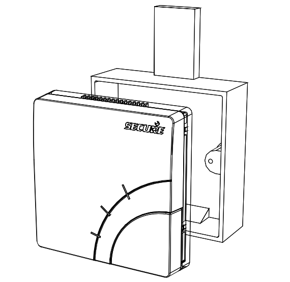
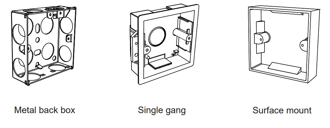
STEP-2 Preparing SIR for surface wall mounting
SIR is suitable for mounting directly onto any surface mounted single-gang molded box having a minimum depth of 25mm for UK, or 35mm for Continental Europe. Cable entry can be made through the most convenient cut-out.
Remove cut-outs before fixing the box in place. Where appropriate, drill the box to provide close-fitting entry for cables and heat-resistant flexible cables. Take care toremove sharp edges.Ensure that the clamp is positioned the right way up. The projections on the underside of the clamp should grip the cable in order to secure it firmly. The cable clamp screws must be adequately tightened, to a torque setting of 0.4Nm.
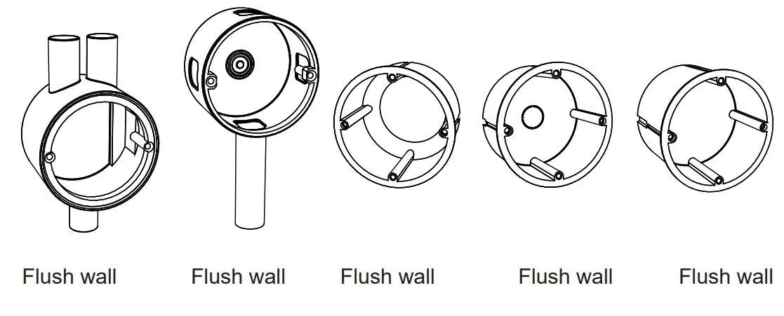
For flush wall mountingThe SIR can be mounted directly to any standard minimum 25mm deep flush mounting single gang wiring box of UK (BS 4662) or 35mm deep flush wall box Europe (DIN 49073). See pictures of gang boxes on page 19.
Clamp all surface wiring to the wall adjacent to the SIR, using trunking where appropriate. The flexible cable to the appliance should be passed through the cable entry hole in the bottom edge of the SIR, and secure under the cable clamp provided.
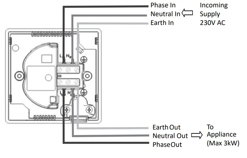
STEP-3 Making connections
Use a twin-and-earth cable with a maximum conductor size of 2.5mm single conductor for the incoming supply to the SIR.
Use a suitably rated three-core flexible cable to connect the SIR to the appliance to be switched. For appliances rated up to 2kW use a minimum of 1.0mm flexible conductors. For appliances rated up to 3kW use 2 minimum 1.5mm flexible conductors. The heat-resistant flexible cable must be used if connecting the SIR to an immersion heater.
| L in | Live in |
| N in | Neutral in |
| Supply earth terminal | |
| Lout | Live out to an appliance |
| N out | Neutral out to an appliance |
| Appliance earth terminal |
All un-insulated earth conductors must be sleeved and connected to the earth terminals on the back of the SIR. The supply earth conductor and appliance earth conductor must use the separate terminal connections provided.Switch off the mains supply and then connect the conductors for the incoming supply and the appliance on the back of the unit, as shown on the next page.
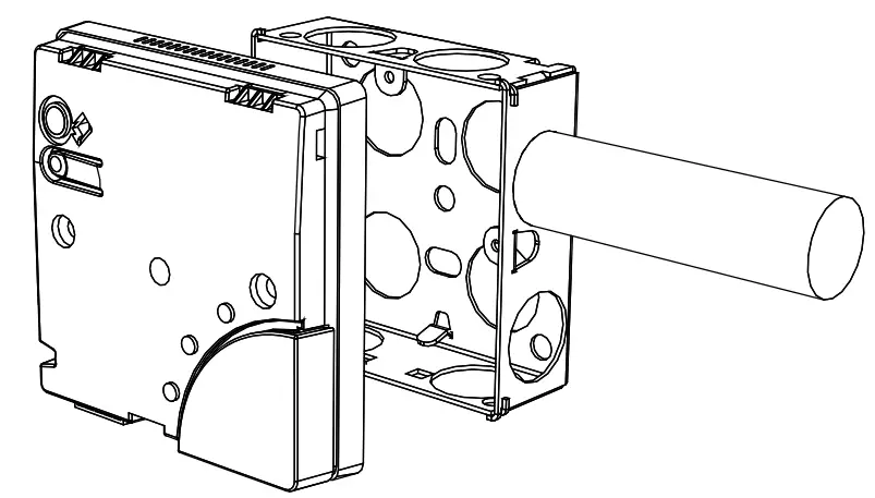
STEP-4 Installing SIR on wall gang / flush wall box
Carefully offer the SIR to the molded/metal box and secure using two screws.Take care not to damage the insulation or trap the conductors when fitting to flush wall box.
STEP-5 Fitting front cover and final check
After fitting the mounting screws, fix the front cover back on. Offer the front cover on to the unit and make sure that it clicks securely in place.
 Finally switch on the mains supply and check that the SIR switches the appliance on and off correctly.
Service and RepairThe SIR is NOT user-serviceable. Please do not dismantle the unit. In the unlikely event of a fault occurring please contact a heating engineer or a qualified electrician.
Technical specifications
Electrical
| Purpose of control | Electronic timer (independentlymounted) |
| Contact rating | 13A resistive*, 230V AC, suitable |
| for loads up to 3kW | |
| Control type | Micro-disconnection |
| Supply | 230V AC, 50Hz only |
| Control action | Type 2B |
| Operation time | |
| limitation | Intermittent |
| Software class | Class A |
| Timing accuracy | (±5%) |
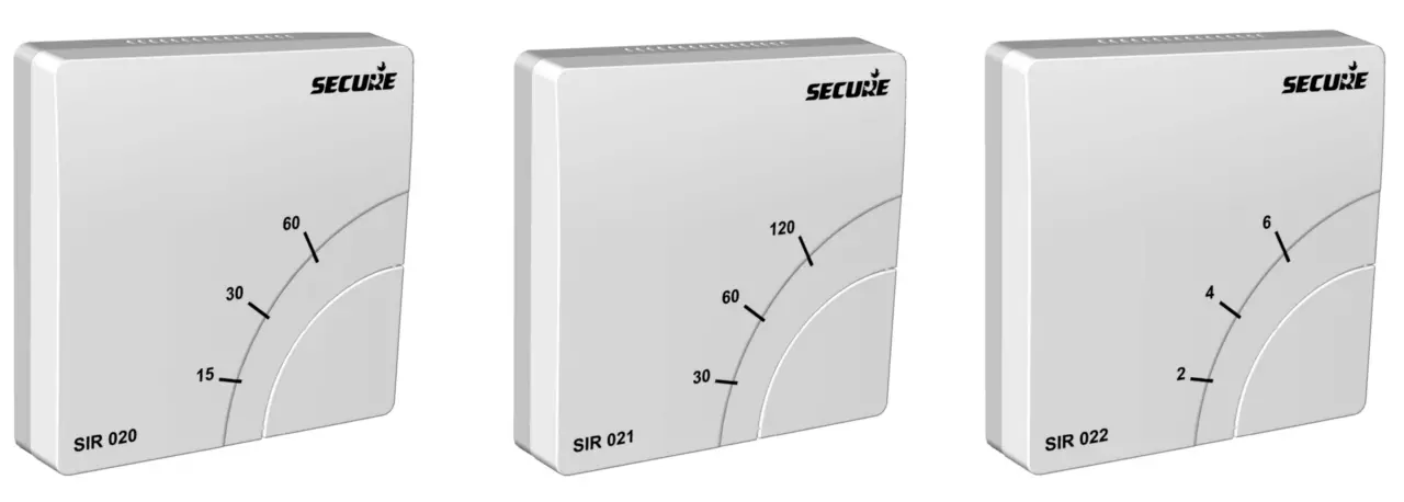
| Timer boost period | Model SIR 020: 15/30/60 minutes |
| Model SIR 021: 30 mins/1 hour/2 hours | |
| Model SIR 022: 2/4/6 hours |
Mechanical
| Dimensions | 85 x 85 x 19mm (flush mount),85 x 85 x 44mm (surface mount) |
| Case material | Thermoplastic, flame retardant |
| Ball pressure test | |
| temperature | 75°C |
| Mounting | Single-gang surface mount / flush |
| Single-gang surface mount / flush | 35mm (Continental Europe) |
| Environmental | |
| Impulse voltage rating | Cat II 2500V |
| Enclosure protection | IP 30 |
| Pollution degree | Degree 2 |
| Operating temperature | |
| range | 0°C to 35°C |
| Compliance | |
| Design standards | EN 60730-2-7, RoHS,BS EN 60730-1, |
Ordering information
SIR 020 15 to 60-minute countdown timer with the single pushbutton operation and LED indicator lights. Suitable for loads up
to 3kW at 230V AC.SIR 021 30 to 120-minute countdown timer with the single pushbutton operation and LED indicator lights. Suitable for loads up
to 3kW at 230V AC.SIR 022 2 to 6-hour countdown timer with single push-button operation and LED indicator lights. Suitable for loads up to 3kW at 230V AC.All the above models are suitable for installation on illustrated types (see page 19) or any other similar type of wall gang/ackboxes.
UK
| Continental Europe | Germany |
![]()
| Secure Meters (UK) LtdSecure House, Lulworth Close,Chandlers Ford,Eastleigh, SO53 3TLUnited Kingdomt: +44 1962 840048 f: +44 1962 841046 | Secure Meters (Sweden) ABRepslagaregatan 43Box 1006, SE-611 32Nykoping, Swedent: +46 155 775 00 f: +46 155 775 97 |
![]()
References
[xyz-ips snippet=”download-snippet”]