
V-5012B INDOOR/OUTDOOR HDVIDEO CAMERAInstallation Guide
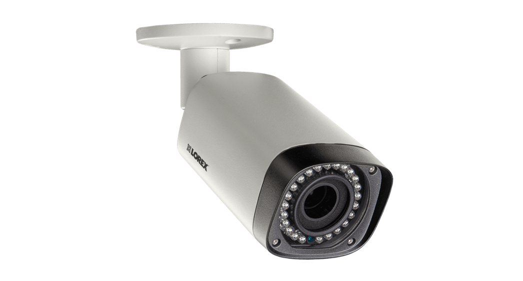
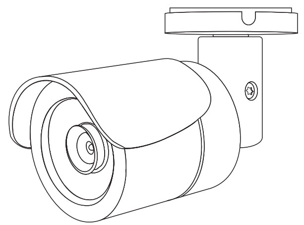 Figure 1: V-5012B Camera
DESCRIPTION
The V‑5012B is a 2.1 Megapixel indoor/outdoor video camera that allows users to view life and recorded HD video clips in Virtual Keypad™. To activate the camera, you need an active Dealer Admin account at dealer.securecomwireless.com.
Compatibility• Any active Virtual Keypad account with SecureCom Cameras & NVRs enabled
What is Included?• One V‑5012B Camera with Mounting Plate• Mounting Template• Hardware Pack with Security Torx L‑key
![]()
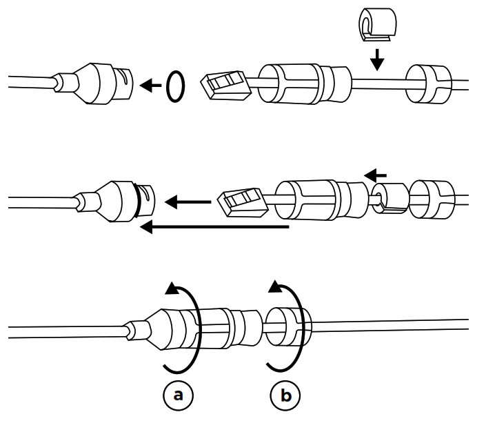
WIRE THE CAMERA
Before connecting the Ethernet cable, install the waterproof Ethernet cap if desired. Refer to Figure 2.
Standard ConnectionConnect a 12 VDC power supply (not included) to the camera power connector. Connect a network cable to the camera Ethernet connector. For compatible power supplies, refer to “Accessories”.
PoE ConnectionConnect a network cable to the camera Ethernet connector. Connect the cable to a PoE switch or injector.
MOUNT THE CAMERA
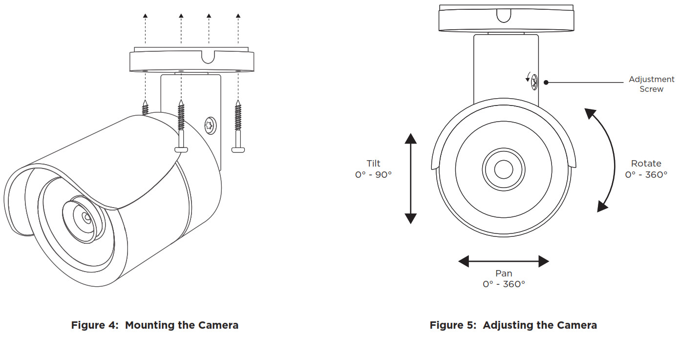
Standard Wall or Ceiling MountRefer to Figure 4 when mounting the camera. Use the included screws and wall anchors to mount the camera base to a wall or ceiling. The mounting surface must be capable of holding five times the camera’s weight.Adjust the CameraRefer to Figure 5 when adjusting the camera.1. Loosen the adjustment screw with the included L‑key.2. Adjust the pan, tilt, and camera rotation angle as needed.3. To lock the camera in place, tighten the adjustment screw with the L‑key.
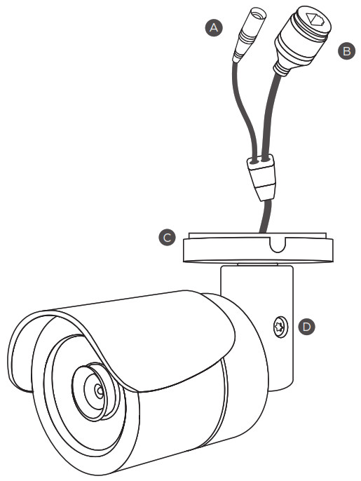 Figure 3: Camera Details
A. 12 VDC Power ConnectorB. Ethernet ConnectorC. Mounting BaseB. Adjustment Screw
ACTIVATE THE CAMERA
After you’ve connected the camera to the network, activate it in Dealer Admin.
- Log in to Dealer Admin.
- Find the customer and select the relevant account number. Select Edit.
- In Video, enable SecureCom Cameras & NVR, then press Save.
- On the System Information page, press the Add Camera button and enter the camera’s 12‑digit MAC Address. Press Next.
- Enter a name for the camera.
- Select the camera’s time zone.
- If the camera image needs to be inverted due to mounting position, toggle Flip Image.
- To configure clip recording options, select Clips.a. If you don’t want this camera to record video clips any time it detects motion, choose Never Record Motion.b. If you want this camera to record video clips any time it detects motion, choose Always Record on Motion.c. If you want the camera to record motion‑triggered clips only when the system is armed, choose Record Motion When Armed.d. To record video clips continuously during the first minute after the system triggers an alarm, select Record on Alarm.
- Press Save.
CONNECT A CAMERA TO THE NVR (Optional)
![]() Note: When managing 5000 Series cameras with both the V‑4408D NVR and Dealer Admin, cameras must be connected to the NVR through a switch.Default Camera Username and PasswordThe default username is scwuser. The password depends on the camera firmware version:
Note: When managing 5000 Series cameras with both the V‑4408D NVR and Dealer Admin, cameras must be connected to the NVR through a switch.Default Camera Username and PasswordThe default username is scwuser. The password depends on the camera firmware version:
- For V‑5012B cameras with lower than D3.2.1_20200818_DMP firmware, the default password is scw12345user.
- For V‑5012B cameras with firmware Version D3.2.1_20200818_DMP and higher, the default password is scw plus the last six alphanumeric characters in the camera’s MAC address. As an example, if the MAC address 1A:2B:3C:4D:5E:6F, the default password is scw4D5E6F.Set Up a Static IPWhen connecting the camera directly to the V‑4408D NVR, you’ll need to configure the camera with a static IP address before connecting the camera to an NVR.
![]() Note: Leave the camera disconnected from the NVR until you’ve finished configuring the static IP.
Note: Leave the camera disconnected from the NVR until you’ve finished configuring the static IP.
- On the NVR monitor, right‑click in the window and select Menu. Enter the username and password that you used during activation.
- Select Camera to open the Camera Management window. Find the NVR camera port that you want to connect the camera to and record its IP address.Note: This IP address may be in a different address range than other IP addresses used on the network.
- Connect the camera to the local network.
- Using the camera’s MAC address, determine the IP that the camera is currently using.
- Open a web browser and enter the camera’s IP address.
- Enter the camera’s default username and password.
- Go to Network > Network Settings.
- In-Network Type, select Static.
- In IP setup, enter the IP address the NVR assigned to the port that you want to use.
- Change the gateway address to the first address on the NVR’s subnet: 192.168.254.1.
- Press Apply. Disconnect the camera from the network, then connect it to the NVR port that you want to use.
Add the Camera to the NVR
- On the NVR monitor, right‑click in the window and select Menu.
- Select Camera to open the Camera Management window.
- Select Edit to open the Edit IP Camera window.
- Set the Adding Method to Manual.
- Set the camera configuration specifics:• Protocol: ONVIF• Management Port: 80
- Enter the username and password:• Username: scwuser• Password: scw12345user or scw + [last 6 of MAC uppercase]
- Press OK. The NVR attempts to connect to the camera.
ADDITIONAL INFORMATION
Enable Email ClipsIf the user would like to be emailed video clips, enable Email Video Clips in Dealer Admin. When this feature is enabled, video clips are emailed to the app user.
- Find the customer and select their name.
- In-App Users, find the user’s row, select the More icon, then select Edit.
- Select Email Video Clips, then press Save.
V-5012B INDOOR/OUTDOOR HD VIDEO CAMERA
 Specifications
Sensor and LensImage Sensor: 2.1 MP, 1/2.7” CMOS
| Sensor and Lens | |
| Image Sensor | 2.1 MP, 1/2.7” CMOS |
| Network | |
| LAN | 802.3 compliant 10/100 LAN |
| IP Protocol | IPv4 |
| Hardware | |
| Power Consumption | |
| 12 VDC | Max 5.6 W |
| PoE (802.3af) | Max 7.3 W |
| Weight | 1.1 lbs (0.5 kg) |
| Dimensions | 6.42” x 2.66” (16.3 cm x 6.75 cm) |
| Housing Material | Aluminum |
| Environmental | |
| Operating Temperature | 14 °F to 122 °F (-10 °C to 50 °C) |
| Operating Humidity | Less than 90% RH, non-condensing |
Ordering Information
| V-5012B | 2.1 MP Indoor/Outdoor HD Video Camera |
| Accessories | |
| 371-500B-W | 12 VDC Power Supply |
CompatibilityAny DMP system with an active Virtual Keypad™ account
INTRUSION • FIRE • ACCESS • NETWORKS2500 North Partnership BoulevardSpringfield, Missouri 65803-8877800.641.4282 | DMP.com
![]()
References
[xyz-ips snippet=”download-snippet”]