
Light MeterOperating Manual
LITE MASTER PROL-478DR-PXL-478DR-A-PXL-478DR-U-PX
This manual is specific for Phottix operation.Please read the operating manual and safety precautions carefully to fully understand the features of this product before use and keep it for future use.Keep the operating manual in a safe place.
Phottix ® is the registered trademark and Strato TM is the trademark of Phottix Hong Kong Ltd.
About Phottix System
1-1. How to use L-478DR-PX Series with Phottix System Products Plug-in external or built-in Phottix receivers are required to work with the Phottix radiosystem.Radio triggering enables a single photographer to easily trigger and control flash units.The radio transmitter built into the L-478DR-PX Series is only compatible with the Phottix radio system.Please read the instruction manuals provided with these products for details about using them.Please go to www.phottix.com/ to learn more about their products and compatibilities.
- Successful radio triggering depends on several factors. Please read these setup steps before using the L-478DR-PX Series to radio trigger flash units.
- It is best to position the meter in sight of the radio receiver.
- Position the radio receiver so that it is away from large metallic objects, concrete, or containers of water (like people).
- When triggering a studio-type flash using the connecting cables included with the Strato II set, be sure to position the Strato II within line of sight so that the Strato II is above the flash body or generator pack.
- Sometimes, conditions do not allow radio reception. These could include strong local radio interference or be near objects that block or absorb the signal. Repositioning the radio, even slightly, can re-establish contact. Alternatively, check to see if the radio receiver is behind objects that absorb or block radio waves, such as concrete, metal, or low hill.
- Operation is the best when the meter to receiver distance is within 30 meters. The working distance of the radio triggering system can vary with the orientation and location of the meter and receivers.
1-2. Turning the Power ON
Press and hold the Power button for about 1 second to start up the meter. The startup screen will be displayed, followed by the Measuring screen.
1-3. Setting Radio Flash Mode in Custom SettingMake sure the Radio Mode is set to “On” in Custom Setting in the meter.1) Press the Menu button on the meter to open the Menu screen.2) Touch [3. Custom Setting] and select [c) Radio Mode] under [6. Flash Mode] in the displayed Menu screen.3) Touch the radio button to select “On” to activate the Radio Flash Mode.
4) Touch [OK] to complete the setting and return to the Custom Setting screen. (Touch[Cancel] to return to the Custom Setting screen without change.)5) Press the Menu button at the Custom Setting screen to return to the top of the Menu screen. Press the Menu button again to return to the Measuring screen.6) In the Radio Flash mode, the Measuring screen shows the setting of the channel number and groups selected.
Channel and groups
Measuring
2-1. Selecting the Channel and Groups1) Touch the Tool Box icon (![]() ) at the bottom right of the Measuring screen to display the Tool Box screen.2) Touch the [STRATO CH/Group] button to display the STRATO CH/Group Setting screen.3) Touch the arrows ▲/▼ or slide your finger over the screen to select a channel from 1to 4.4) Touch one or more Groups (A, B, C, D) to select the flash Groups you want to use.* Groups to use can be selected from Flash Control screen as well.5) Touch [OK] to confirm settings and return to the Measuring screen. (Touch [Cancel] to go back to the Measuring screen without change.)
) at the bottom right of the Measuring screen to display the Tool Box screen.2) Touch the [STRATO CH/Group] button to display the STRATO CH/Group Setting screen.3) Touch the arrows ▲/▼ or slide your finger over the screen to select a channel from 1to 4.4) Touch one or more Groups (A, B, C, D) to select the flash Groups you want to use.* Groups to use can be selected from Flash Control screen as well.5) Touch [OK] to confirm settings and return to the Measuring screen. (Touch [Cancel] to go back to the Measuring screen without change.)![]()
 Set both the meter and plug-in external or built-in Phottix receivers to the same channel and Group(s) to use.
- The last selected Groups in either Flash Control screen or STRATO CH/Group Setting screen in Tool Box are activated in Measuring screen.
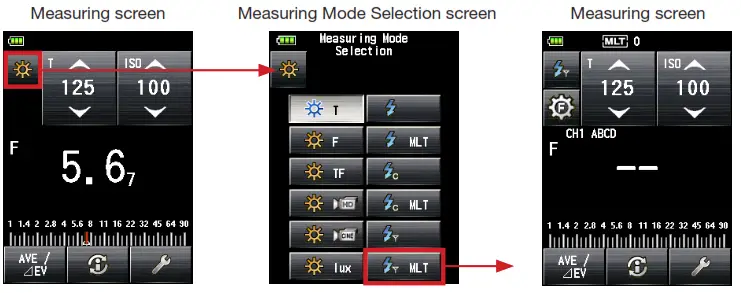
2-2. Measuring in Radio Flash Mode2-2-1. How to use Radio Triggering1) Touch the Measuring mode icon ( ![]() ) at the top left of the Measuring screen and thenselect the Radio Flash Mode (
) at the top left of the Measuring screen and thenselect the Radio Flash Mode (![]() ).
).![]()
![]() 2) Set ISO sensitivity on the ISO icon.3) Set shutter speed on the T (shutter speed) icon.4) Make sure that the channel and Groups are the same for the meter and receivers in use.* Select the Group to trigger from the Flash Control screen(See below) or Tool Box. Then return to the Measuring screen to take the flash measurement.5) Press the Measuring button to trigger the flash units. The measured value (f-stop) is displayed.
2) Set ISO sensitivity on the ISO icon.3) Set shutter speed on the T (shutter speed) icon.4) Make sure that the channel and Groups are the same for the meter and receivers in use.* Select the Group to trigger from the Flash Control screen(See below) or Tool Box. Then return to the Measuring screen to take the flash measurement.5) Press the Measuring button to trigger the flash units. The measured value (f-stop) is displayed.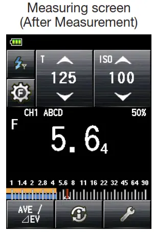
- When firing the flash, if the flash brightness is 8EV lower than the ambient light, the meter may fail to detect the flashlight. In this case, make measurements using the Cord (PC) Flash Mode (See L-478 Series Common Operating Manual for details).
- Rapid start fluorescent lamps and special lighting are sometimes mistaken for flash and accidentally measured. In this case, make measurements using the Cord (PC) Flash Mode (See L-478 Series Common Operating Manual for details)
- The waveform of a flashbulb has a slight slope and there is a possibility that the light meter cannot recognize the flashbulb in Cordless Flash Mode. In this case, make measurements using theCord (PC) Flash Mode (See L-478 Series Common Operating Manual for details).
2-2-2. How to use Flash Control Mode1) Touch the Flash Control icon ( ) on the Measuring screen to display the Flash Control screen.2) Select one or more Groups (A to D) 3 and press the Measuring button to trigger the flash units for the selected Groups.3) The measured value is displayed at the center of screen 1 and over the selected Group button 2 .4) Manually set the flash power level to the flash unit.5) Press the Measuring button to trigger the flash again for measurement to confirm that the flash power is set to the desired value.6) Repeat 2) to 5) above to select and measure otherGroups 3 until all flash units have been measured and the desired F-number is above each Group button 2.7) Select all Groups you want to use for the final exposure measurement, and press the Measuring button. The measured value for each Group 2 will not change.The F-number for the measured brightness of all lights will be displayed in the center of screen 1 as total exposure.* To set ISO sensitivity and shutter speed, press the Radio Flash Mode icon (![]() ) to go back to the Measuring screen.
) to go back to the Measuring screen. * If you want to change the channel, press the CH/Group Selection icon (
![]() ) to directly go to Strato CH/Group Setting screen (black background). When pressing [OK], the screen goes back to the Group Measuring screen.
) to directly go to Strato CH/Group Setting screen (black background). When pressing [OK], the screen goes back to the Group Measuring screen.
2-3. Measuring in Radio Multiple (Cumulative) Flash Mode1) Touch the Measuring mode icon (![]() ) at the top left of the Measuring screen and then select the Radio Multiple (Cumulative) Flash Mode (
) at the top left of the Measuring screen and then select the Radio Multiple (Cumulative) Flash Mode (![]() )
)
![]() 2) Set ISO sensitivity on the ISO icon.3) Set shutter speed on the T (shutter speed) icon.4) Make sure that the channel and Group are the same for the meter and receivers in use.* Select the Group to trigger from the Flash Control screen(See below) or Tool Box. Then return to the Measuring screen to take the flash measurement.5) Press the Measuring button to trigger the flash units. The measured value (f-stop) is displayed.6) Repeat 5) above until you get the accumulated measured value (f-stop) you want to use. Thenumber of cumulative flashes is displayed at the top of the screen.* It is not possible to take cumulative flash measurements while the meter displays the Flash Control screen. Be sure to set the meter to display the main Measuring screen when taking cumulative flash measurements. The measured value will be cleared when going from the Measuring screen to the Flash Control screen when in Radio Multi (Cumulative) Flash Mode.
2) Set ISO sensitivity on the ISO icon.3) Set shutter speed on the T (shutter speed) icon.4) Make sure that the channel and Group are the same for the meter and receivers in use.* Select the Group to trigger from the Flash Control screen(See below) or Tool Box. Then return to the Measuring screen to take the flash measurement.5) Press the Measuring button to trigger the flash units. The measured value (f-stop) is displayed.6) Repeat 5) above until you get the accumulated measured value (f-stop) you want to use. Thenumber of cumulative flashes is displayed at the top of the screen.* It is not possible to take cumulative flash measurements while the meter displays the Flash Control screen. Be sure to set the meter to display the main Measuring screen when taking cumulative flash measurements. The measured value will be cleared when going from the Measuring screen to the Flash Control screen when in Radio Multi (Cumulative) Flash Mode.![]()
![]()
- When firing the flash, if the flash brightness is 8EV lower than the ambient light, the meter may fail to detect the flashlight. In this case, make measurements using the Cord (PC) Flash Mode (See L-478 Series Common Operating Manual for details).
- Rapid start fluorescent lamps and special lighting are sometimes mistaken for flash and accidentally measured. In this case, make measurements using the Cord (PC)Flash Mode (See L-478 Series Common Operating Manual for details)
- The waveform of a flashbulb has a slight slope and there is a possibility that the light meter cannot recognize the flashbulb in Cordless Flash Mode. In this case, make measurements using the Cord (PC) Flash Mode (See L-478 Series Common Operating Manual for details).
![]()
Functions
3-1. Custom Setting FunctionThis enables a quick and easy setup of individual meter preferences.For other Custom Settings, please refer to the L-478 Series Common Operating Manual.Custom Setting specific to L-478DR-PX Series for Phottix is as follows
3-1-1. Custom Setting Function List
|
Setting No. |
Custom Setting Name | Item |
Default Setting |
||
| 6 | Flash Mode*1 | On | Off | – | On |
| c) | Radio Mode*1 | On | Off | – | On |
*1 When Flash Mode is set to “Off”, the sub-settings of all-flash modes: a) CordlessMode to d) Multiple (Cumu.) Flash Mode cannot be selected.
3-1-2. How to enter Custom Setting
1) Press the Menu button on the meter to open the Menu screen.2) Touch [3.Custom Setting] and select [c)Radio Mode] under [6. Flash Mode] in the displayed menu screen.3) Touch the radio button to select On or Off.![]()
4)Touch [OK] to complete the setting and return to the Custom Setting screen. (Touch [Cancel] to return to the Custom Setting screen without change.)5) Press the Menu button at the Custom Setting screen to return to the top of the Menu screen. Press the Menu button again to return to the Measuring screen.
Specifications
Radio wave frequency band:2.4GHzChannel:1 to 4Group: A to DRadio triggering range: 30 meters (100 feet)
![]() • The working distance of the radio triggering system can vary with the orientation and location of the meter and receivers.
• The working distance of the radio triggering system can vary with the orientation and location of the meter and receivers.
Legal Requirements
Legal RequirementsThis product complies with the following legal requirements.
| Destination | Standard | Details | |
| Europe | SAFETY | EN 60950-1EN 62368-1 | |
| EMC | EMS: EN 55024:EN 55035EMI : EN 55032 | ||
| Wireless | RE Directive, REDEN 300 440-2EN 301 489-1EN 301 489-17 EN 62479:2010 | ||
| Environmental | WEEE, RoHS, REACH | ||
| North America | FL( us) |
EMC | FCC Part15 SubpartB ClassB |
| Wireless | FCC Part15 SubpartC | ||
| IC (Canada) | EMC | ICES-003 | |
| Wireless | RSS-210 |
FCC & IC compliance information
![]() Warning
Warning
- Changes or modifications to this unit not expressly approved by the party responsible for compliance could void the user’s authority to operate the equipment.
- This equipment has been tested and found to comply with the limits for a Class B digital device, pursuant.
To Part 15 of the FCC Rules. These limits are designed to provide reasonable protection against harmful interference in a residential installation. This equipment generates, uses, and can radiate radio frequency energy and, if not installed and used in accordance with the instruction, may cause harmful interference to radio communication.
However, there is no guarantee that interference will not occur in a particular installation.If this equipment does cause harmful interference to radio or television reception, which can be determined by turning the equipment off and on, the user is encouraged to try to correct the interference by one or more of the following measures:
* Reorient or relocate the receiving antenna.* Increase the separation between the equipment and receiver.* Consult the dealer or an experienced radio/TV technician for help.
This device complies with Part 15 of the FCC rules and also with RSS-210 of Industry Canada. Operation is subject to the following two conditions: (1) This device may not cause harmful interference, and (2) this device must accept any interference received, including interference that may cause undesired operation.
|
Model |
FCC ID Number | IC Number |
Note |
| L-478DR-PX | 2AGF8-TXMEPA | 20931-TXMEPA | The approval of this rule is obtained with a radio transmitter module. |
SEKONIC CORPORATION
7-24-14, Oizumi-Gakuen-cho, Nerima-ku Tokyo178-8686 JAPANTEL +81-3-3978-2335 FAX +81-3-3978-5229https://www.sekonic.com©2015-2020 SEKONIC CORPORATION All Rights Reserved.JR6L97651December 2020
References
[xyz-ips snippet=”download-snippet”]