![]()
Radiant Cooktop: SCR3042FB, SCR3041GB, SCR2442FBINSTALLATION MANUAL
SPECIAL WARNINGINSTALLATION AND SERVICE MUST BE PERFORMED BY A QUALIFIED INSTALLER.IMPORTANT: SAVE THIS INSTALLATION MANUAL FOR LOCAL ELECTRICAL INSPECTOR’S USE.READ AND SAVE THESE INSTRUCTIONS FOR FUTURE REFERENCE.
IMPORTANT NOTES TO THE INSTALLER
- Read all of the Installation Manual before installing the Radiant Cooktop.
- Remove all packing material before connecting the electrical supply.
- Observe all governing codes and ordinances.
- Be sure to leave these instructions with the consumer.
- All cooktops must be hard wired (direct wired) into an approved junction box. A “plug and receptacle” is not permitted on these products.
IMPORTANT SAFETY INSTRUCTIONS
 WARNING If the information in this manual is not followed exactly, a fire or electrical shock may result from that could cause property damage, personal injury, or death.
WARNING Never leave children alone or unattended in the area where a cooktop is in use.
WARNING Stepping, leaning, or sitting on the cooktop may result in serious injuries and can also cause damage to the cooktop.
- For Your Safety: Do not store or use gasoline or other flammable vapors and liquids in the vicinity of this or any other appliance.To eliminate the risk of burns or fire due to overheating, cabinets located above the radiant unit should be avoided. If cabinet space is available, the risk can be reduced by installing a range hood that protects horizontally at a minimum of 5 inches below the bottom of the cabinets
- To prevent accidents and achieve optimal ventilation, allow for sufficient space around the cooking area.
IMPORTANT INSTALLATION INFORMATION
- Dimensions that are shown in Figures 3 & 7 must be used. Given dimensions provide minimum clearance.
- Contact surface must be solid and level.
- Check the location where the cooktop will be installed for proper electrical supply. Approximate location of the junction box, min 12″(304.8 mm) below the cooktop. See Figure 4.
- Your cooktop can be installed into a countertop by itself, above a gas or electric wall oven, above a microwave drawer, or above a convection microwave drawer.
- All-electric cooktops run off a single-phase, three-wire cable, 240V/60Hz AC only electrical supply with a ground. The minimum distance between cooktop and overhead cabinetry is 30″.
PART INCLUDED
| PARTS | QTY. |
| Cushion Tape # PCUSGB125MRP0 770 mm x 6 mm x 2 mm | 2 |
| Cushion Tape # PCUSGB126MRP0 540 mm x 6 mm x 2 mm | 2 |
BEFORE INSTALLING THE COOKTOP
- Visually inspect the cooktop for damage. Also, make sure all cooktop screws are on tight.
- Record the model and serial number as found on the bottom of your cooktop. When ordering parts for or making inquiries about your cooktop, always be sure to include the model and serial numbers and a lot number or letter from the serial plate on your cooktop.
- Prepare the cutout dimensions of the countertop.
- Make sure the wall coverings, countertop, and cabinets around the cooktop can withstand heat (up to 200°F) generated by the cooktop.
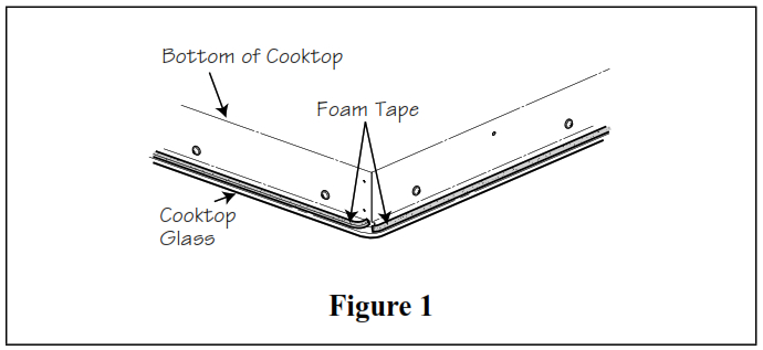
- Apply the included cushion tape around the outer edge of the glass on all four sides. Do not overlap the tape. See Figure 1.
- Gently lower the cooktop into the countertop cutout.
NOTE: Do not seal the cooktop to the countertop, the cooktop must be removable if service is necessary.
ELECTRICAL CONNECTION
The Radiant Cooktops must connect to a separate, single-phase, AC-only electrical supply with their own circuit breaker. These appliances must be installed in accordance with National Electrical Codes, as well as all state, municipal and local codes. This appliance must be supplied with the proper voltage and frequency and amperage, which is protected by a properly sized circuit breaker or time-delay fuse.
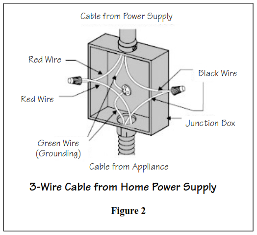
WARNINGThe cable from the appliance is equipped with3-wire.IMPORTANT: Use the 3-wire cable from Home Power Supply where local codes permit a 3-wire connection.
Use the 4-wire cable from Home Power Supply where local codes do not allow grounding through neutral.Connecting to a 3-wire power OR 4-wire power supply cable electrical system:
- Disconnect the power supply.
- In the circuit breaker, fuse box, or junction box, connect appliance and power supply cable wires as shown below (3-wire, Figure 2; 4-wire, Figure 3).
- Circuit breaker fuse rating must be above 40 A, and wire should be 2/8 or 3/8 copper.
- Minimum acceptable size of conductors should be no less than 10AWG, copper only, and no less than 167°F.
- A wire-binding screw or stud used in the wire terminal should be 10 or larger.
WARNING
- The electrical power to the cooktop must be shut off while line connections are being made. Failure to do so could result in serious injury or death.
- An extension cord must not be used with this appliance. Such use may result in a fire, electrical shock, or another personal injury.

![]() WARNINGThe cooktop conduit wiring is approved for copper wire connection only, if you have aluminum house wiring, use only special connectors which are approved for joining copper and aluminum wires and conform with local codes and ordinances. Follow the electrical connector manufacturer’s recommended procedure closely. IMPORTANT – Save for the local electrical inspector’s use.
WARNINGThe cooktop conduit wiring is approved for copper wire connection only, if you have aluminum house wiring, use only special connectors which are approved for joining copper and aluminum wires and conform with local codes and ordinances. Follow the electrical connector manufacturer’s recommended procedure closely. IMPORTANT – Save for the local electrical inspector’s use.
INSTALLATION – 30” MODELS SCR3042FB & SCR3041GB
COOKTOP AND CUTOUT DIMENSIONS (See Figure 4)
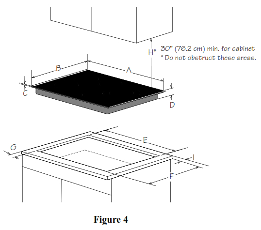
| A. 30” (762 mm) | F. 19-11/16” (500 mm) |
| B. 21” (533 mm) | G. Minimum: 2” (51 mm) |
| C. 3/16” (5 mm) | H. Minimum: 30” (762 mm) |
| D. 2-5/16” (59 mm) | I. Minimum: 2” (51 mm) |
| E. 28-5/8” (727 mm) |
COOKTOP CUTOUT OPENING DIMENSIONS (See Figure 5)
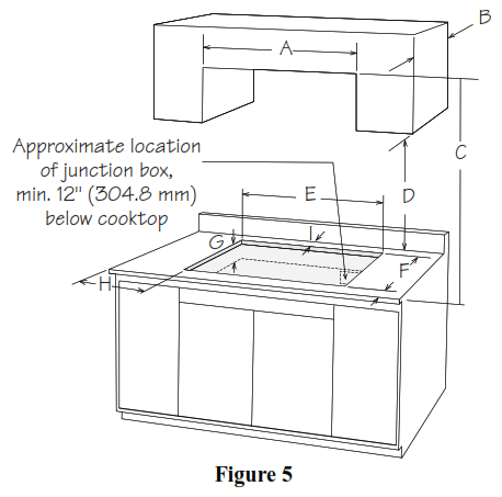
| A. 30” (762 mm) | F. 19-11/16” (500 mm) |
| B. 13” (330 mm) | G. 4-1/2 (114 mm) |
| C. 30” (762 mm) min to unprotected wood | H. Minimum: 2” (51 mm) |
| D. 18” (457 mm) | I. Minimum: 2” (51 mm) |
| E. 28-5/8” (727 mm) |
INSTALLATION – 24” MODEL SCR2442FB
COOKTOP AND CUTOUT DIMENSIONS (See Figure 7)

| A. 24” (610 mm) | F. 19-11/16” (500 mm) |
| B. 21” (533 mm) | G. Minimum: 2” (51 mm) |
| C. 3/16” (5 mm) | H. Minimum: 30” (762 mm) |
| D. 2-5/16” (59 mm) | I. Minimum: 2” (51 mm) |
| E. 22-3/8” (568 mm) |
COOKTOP CUTOUT OPENING DIMENSIONS (See Figure 8)
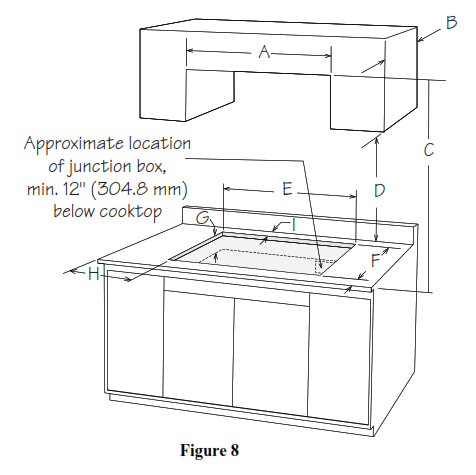
| A. 24” (610 mm) | F. 19-11/16” (500 mm) |
| B. 13” (330 mm) | G. 4-1/2″ min (114 mm) |
| C. 30” (762 mm) min to unprotected wood | H. Minimum: 2″ (51 mm) |
| D. 18” (457 mm) | I. Minimum: 2” (51 mm) |
| E. 22-3/8” (568 mm) |
AFTER INSTALLATION
- Remove all the stickers and items from the top of the cooktop surface.
- Clean the cooktop before use. Dry with a soft cloth. See Cleaning and Care in the operation manual for reference.
- Read “Using the Cooktop” in the operation manual.
- Turn on the power to the cooktop.
- Verify all functions operate properly.
NOTE: If the cooktop does not work, or you find any problem in its operation, please check that the circuit breaker has not tripped, or a fuse has not blown. For more information, please See Before You Call for Service in the operation manual. If you do not solve the problem by yourself, please please contact us at 1-800-BE-SHARP for assistance or service.
![]()
SHARP ELECTRONICS CORPORATION
- 100 Paragon Drive
- Montvale, New Jersey 07645
- USA
SHARP ELECTRONICS OF CANADA LTD
- 335 Britannia Road East
- Mississauga, Ontario
- L4Z 1W9
- Canada
[xyz-ips snippet=”download-snippet”]