Shure 444D Megnetic Controled Fixed
Microphone User Manual

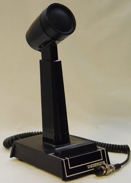
CONTROLLED MAGNETIC® FIXED STATION MICROPHONE

GENERAL
The Shure Model 444D is a dual-impedance CONTROLLED MAGNETIC® fixed station microphone with a frequency response tailored for optimum speech intelligibility. The microphone has a multitude of features designed especially for the radio amateur. It has two easily accessible slide switches (impedance selection and Normal or VOX operation) and a smoothly operating, momentary or locking push-to-talk switch bar. The push-to-talk switch is a Shure Million-Cycle double-pole, double-throw leaf type. The leaf switch and four wire (three conductors plus shield) cable are arranged for easy connection to any ham rig. De isolation on the microphone circuit provides compatibility with radio inputs designed for powered microphones. The coiled cord ensures a neat and uncluttered ham shack appearance. The microphone has a height adjustment to promote operator comfort in transmitting. The high-impact ARMO-DUR® case construction is virtually indestructible, comfortable to the touch in any temperature or humidity, and impervious to rust or corrosion.
The 444D is supplied with an Amateur Radio Wiring Guide with instructions for connection to many of the most popular transmitters. For those who want a straight cable, one is available as Shure Part Number90BR2600. The microphone can be converted to Monitor/Transmit switching with the Shure RK199S Split-Bar Conversion Kit.
Microphone Features:
- High-output, durable, totally reliable CONTROLLED MAGNETIC cartridge
- Response tailored for speech intelligibility
- Switch selectable high or low impedance
- Normal/VOX switch on microphone
- Double-pole, double-throw, Million-Cycle leaf-type push-to-talk switch with momentary or locking switch bar
- De-isolated microphone circuit, compatible with debiased inputs designed for powered microphones
- Three-conductor, one-conductor shielded, coiled cable
- Cable and switch arranged for instant connection to grounded or isolated transmitter keying
- Rubber feet keep microphone from slipping
- Height adjustment for operator comfort
- Strong ARMO-DUR case, impervious to rust and corrosion
- Conversion kit available for Monitor/Transmit switching
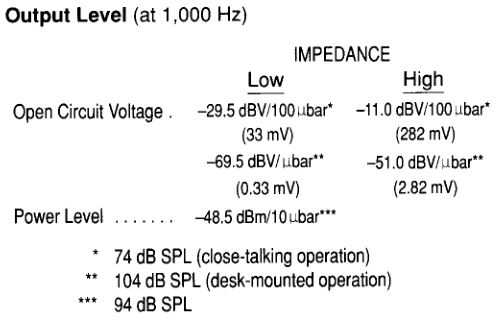
SPECIFICATIONS
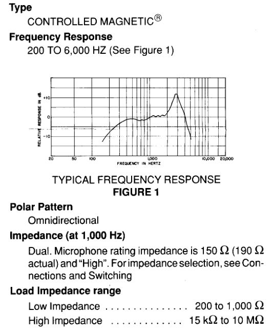
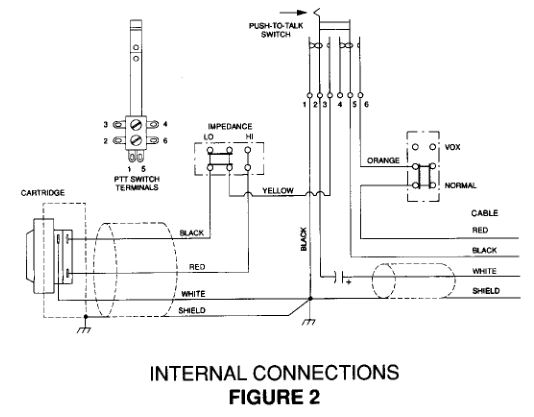
SwitchesPush-to- Talk, double-pole, double-throw, MillionCycle leaf-type, momentary or locking, to actuate microphone circuit and transmitter grounded or isolated keying circuit (see Figure 2)Impedance-Selection, slide switch on underside of base, for high- or low-impedance audio inputs Normal/VOX, slide switch on underside of base for Normal (push-to-talk) or VOX (voice-operated) transmitter keying. Push-to-talk switch must be locked On for VOX operation.
Cable2.1 m (7 ft) three-conductor, one-conductor shielded, rubber-jacketed, attached, coiled cable. Retracted coil length approximately 30.5 mm (12 in.)
CaseBlack, high-impact ARMO-DUR®
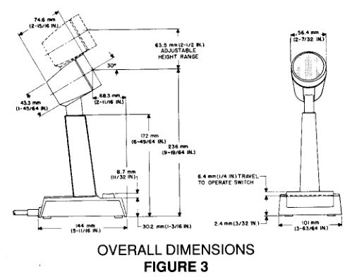
DimensionsSee Figure 3
Net Weight784 grams (1 lb, 12 oz)
Packaged Weight1 .07 kg (2 lb, 6 oz)
CONNECTIONS
Instructions for connecting the microphone to many amateur radios are in the enclosed Amateur Radio Wiring Guide. The cable leads and push-to-talk switch are arranged to permit immediate hookup to transmitters with either isolated or grounded switching. In addition, the audio lead is de-isolated to ensure compatibility with circuits biased for use with powered microphones.
A piece of tubing is attached to the plug end of the cable for use as a strain relief for plugs with large cable entry holes. Remove the tubing when it is not required.
The general wiring procedure is as follows.
Phone PlugFor radios that use a phone plug, the normal connections are: RED lead to the tip; WHITE lead to the ring, and SHIELD and BLACK lead to the sleeve.
Microphone Audio Input CircuitConnect the WHITE lead to the audio input terminal; connect the SHIELD to the ground terminal.
NOTE: The audio circuit is grounded in receive. If the transmitter requires that the audio circuit be floating in receive, remove the two screws on the underside of the base. Separate the base from the microphone, taking care not to damage any leads. Cut and remove the BLACK lead between switch terminal 1 and the ground lug (see Figure 2.) Reassemble the base to the microphone.
Grounded or Isolated Switching CircuitMany transmitters ground a relay or de switching circuit to key the transmitter. For these units, connect the RED lead to the switching terminal; connect the BLACK lead to the ground terminal along with the SHIELD.
Some transmitters close an isolated switching circuit to key the transmitter. For these units, connect the RED lead to one switching terminal; connect the BLACK lead to the other switching terminal.
SWITCHING
This microphone has two slide switches on the underside of the base to select high or low impedance and Normal (push-to-talk) or VOX (voice-operated) keying of a transmitter. The push-to-talk switch is a momentary or locking type.
Push-to-Talk SwitchThe push-to-talk switch can be used for momentary transmission by depressing and then releasing it. For longer transmissions, or for VOX operation, lock the switch On by depressing it and sliding it forward. To unlock, slide the switch toward the rear of the microphone and release.
Because the push-to-talk switch connects the microphone audio to the transmitter, it can be released to immediately disable the transmitter VOX circuit if a loud noise inadvertently keys the transmitter in VOX operation.
Impedance SwitchSet the impedance switch on the underside of the base to either high or low impedance to match the transmitter audio input impedance. If you are not certain which impedance to use, set the switch for “LO” and check whether there is sufficient output to obtain 100% modulation on the transmitter. If the output is too low, change the switch setting to “HI”.
If the switch is incorrectly set to “HI” for a low-impedance transmitter, some of the symptoms may include low volume and a lack of intelligibility or a bassy sound.
Function SwitchFor push-to-talk operation, set this switch (on the underside of the base) to “Normal” and momentarily depress or lock the push-to-talk switch On for transmission.
For VOX operation, set the switch to “VOX” and lock the push-to-talk switch On. When the transmitter VOX controls have been correctly adjusted, the transmitter will then be automatically keyed by the operator’s voice.
NOTE: Setting the 444D for VOX with transmitters that do not have VOX circuits will result in disabling the transmitter keying circuit.
OPTIONAL CONVERSIONS
To increase the versatility of the Model 444D microphone, two optional modifications are available.A 2.2 m (7 ft) straight cable is available as Shure Part Number 90BR2600.
A split-bar Transmit/Monitor Switch is available for use with transceivers having a receiver squelch circuit. Depressing the Monitor bar disables the receiver squelch circuit so that the operator can determine the presence of signals below the squelch threshold before transmitting. The Monitor switch is either momentary or locking; and the switch can be wired either to ground or to unground the squelch circuit. The Transmit switch bar can be depressed only while the Monitor bar is depressed, thus requiring the operator to verify that the channel is idle before transmitting. The Transmit switch is momentary only and cannot be locked. The Transmit/Monitor Switch Kit is Shure Model RK199S. General microphone wiring instructions are supplied with the kit, but specific transceiver wiring details must be obtained from the transceiver schematic and/or the manufacturer of the unit.
REPLACEMENT PARTS
Cartridge _______________________R 111Cable __________________________70A549Screen and Grille Assembly _________90F1060Push-to-Talk Leaf Switch___________90A3695Base Plate and Switch assembly______ 90A2992HI/LO Impedance Slide Switch______55C119Normal/VOX Slide Switch__________55A 119
OPTIONAL CONVERSION PARTS
Straight Cable . . . . . . . . . . . . . . . . . . . . . . . . . . . .90BR2600Transmit/Monitor Split-Bar Switch Kit . . . . . . . RK199S
Shure 444D Megnetic Controled Fixed Microphone User Manual – Shure 444D Megnetic Controled Fixed Microphone User Manual –
[xyz-ips snippet=”download-snippet”]