SHURE A400MB Mute Button User Guide
IMPORTANT SAFETY INSTRUCTIONS
- READ these instructions.
- KEEP these instructions.
- HEED all warnings.
- FOLLOW all instructions.
- DO NOT use this apparatus near water
- CLEAN ONLY with dry cloth.
- DO NOT block any ventilation openings. Allow sufficient distances for adequate ventilation and install in accordance with the manufacturer’s instructions.
- DO NOT install near any heat sources such as open flames, radiators, heat registers, stoves, or other apparatus (including amplifiers) that produce heat. Do not place any open flame sources on the product.
- DO NOT defeat the safety purpose of the polarized or grounding type plug. A polarized plug has two blades with one wider than the other. A grounding type plug has two blades and a third grounding prong. The wider blade or the third prong are provided for your safety. If the provided plug does not fit into your outlet, consult an electrician for replacement of the obsolete outlet.
- PROTECT the power cord from being walked on or pinched, particularly at plugs, convenience receptacles, and the point where they exit from the apparatus.
- ONLY USE attachments/accessories specified by the manufacturer.
- USE only with a cart, stand, tripod, bracket, or table specified by the manufacturer, or sold with the apparatus. When a cart is used, use caution when moving the cart/apparatus combination to avoid injury from tip-over.

- UNPLUG this apparatus during lightning storms or when unused for long periods of time.
- REFER all servicing to qualified service personnel. Servicing is required when the apparatus has been damaged in any way, such as power supply cord or plug is damaged, liquid has been spilled or objects have fallen into the apparatus, the apparatus has been exposed to rain or moisture, does not operate normally, or has been dropped.
- DO NOT expose the apparatus to dripping and splashing. DO NOT put objects filled with liquids, such as vases, on the apparatus.
- The MAINS plug or an appliance coupler shall remain readily operable.
- The airborne noise of the Apparatus does not exceed 70dB (A).
- Apparatus with CLASS I construction shall be connected to a MAINS socket outlet with a protective earthing connection.
- To reduce the risk of fire or electric shock, do not expose this apparatus to rain or moisture.
- Do not attempt to modify this product. Doing so could result in personal injury and/or product failure.
- Operate this product within its specified operating temperature rang.
 |
This symbol indicates that dangerous voltage constituting risk of electric shock is present within this unit |
 |
This symbol indicates that there are important operating and maintenance instructions in the literature accompanying this unit. |
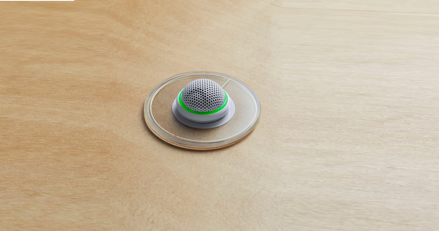
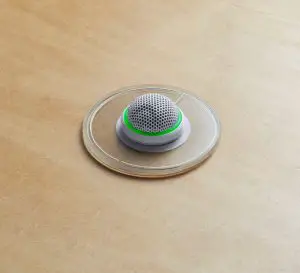
The Shure A400MB mute button accessory is compatible with the MX395-LED and MX400SMP, with a low profile design ideal for surface mounting to boardroom tables. The switch adds a programmable button for microphone LEDs and local or remote mute control with Shure products or third-party control systems.
A400MB Parts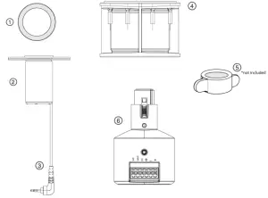
- Color RingPlace around drilled hole to match microphone color.
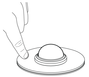
- Mute buttonTouch to mute microphone.
- Mute button cableConnect to the plug-on adapter.
- SpacerUse the spacer to adjust to different table thicknesses. Pull the mute button cable through the gap.
- WingnutUse to tighten the mute button under the table. Included with MX395 and MX400SMP only.
- Plug-on adapterSits underneath the table surface, provides power, and controls signals to the mute button.
What’s in the Box
- Mute button
- Plug-on adapter
- Spacer Color rings (3)
- Assembly kit (90A48840)
- Flathead screwdriver
- Cable ties (2)
- Strain reliefs (2)
- Terminal plug
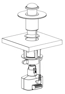
Installing the Mute ButtonThe mute button fits in tables that are between 15 to 30 mm (.59 to 1.18 inches) thick.
- Drill a 30 mm (1 1/8 inch) hole in the table.
- Place the color ring around the hole.
- Insert the mute button and its cable into the hole.Note: Remove the protective blue film from the top of the mute button.
- Insert a compatible microphone into the mute button.
- Slide the spacer onto the mute button so the rubber side is flush against the bottom of the table.
- Pull the cable through the side opening on the spacer.
- Slide a wingnut under the spacer and tighten by hand, and then turn an additional 90 degrees (¼ turn). Do not overtighten the wingnut.
- Connect the adapter to the 5-pin XLR microphone.
- Plug the mute button cable into the adapter.
- Wire a cable to the 6-pin block connector and connect to the adapter.
Phantom PowerThe mute button requires a 48 V phantom power source.
LED Logic
Use the included 6-pin block connector to wire the microphone to a DSP or other logic-enabled device, such as the ANI22- BLOCK or ANI4IN-BLOCK.
A400MB Pin Assignments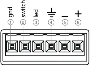
Note: The block connector screw terminals face downwards so they are accessible from under the table after installation.
- Logic Ground
- Switch (sent from microphone)
- LED (received by microphone)
- Audio Ground
- Audio
- Audio +
DIP Switches
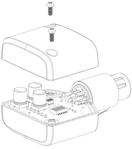
Accessing the DIP SwitchesDisconnect the adapter from the A400MB and any logic devices before disassembly. Remove the 2 Phillips head P1 size screws from the base of the adapter.
DIP Switch SettingsUse the DIP switches to configure logic settings and mute button behavior. DIP switches are down by default, and settings can only be changed when the device is powered off. Changes take effect when the mute button is powered back on.
| DOWN (default) | UP | |
| 1 | Toggle | Momentary |
| 2 | Push-to-Mute | Push-to-Talk |
| 3 | Local Mute | Logic Control |
| 4 | Green LED = talk, Red LED = mute | Red LED = talk, Green LED = mute |
| 5 and 6 work together to make 4 touch sensitivity settings: 1 (lowest) – 4 (highest) | 5 UP, 6 DOWN = 1 | |
| 5 DOWN, 6 DOWN = 2 (default) | ||
| 5 DOWN, 6 UP = 3 | ||
| 5 UP, 6 UP = 4 |
Note: Higher sensitivity settings are more likely to cause accidental touch responses.
Connecting to a Logic-Enabled Device
Use these settings if connecting the microphone to a logic-enabled device, such as the ANI4IN-BLOCK or ANI22-BLOCK:
- Connect the A400MB LED (input) to the ANI LED (output) to illuminate the microphone LED when the logic signal changes.*
- Connect the A400MB switch (output) to the ANI switch (input) to send a logic signal from the A400MB to the ANI.*
- Set DIP switch 3 to up. This disables local muting. Pressing the A400MB sends a logic signal (the microphone passes audio regardless of whether the button is pressed or not).
- Set DIP switches 1 and 2 to configure how the A400MB sends SWITCH OUT logic.
Connections and Signal Flow
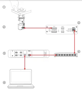
- MX395-LED:Runs the audio signals and features logic connections to receive logic mute and LED control signals.
- A400MB:Adds programmable button for microphone LEDs and mute control, and connects to analog input.
- ANI22IN-BLOCK:Connects microphones to the audio network and converts analog to Dante.
- Network Switch:Provides Power over Ethernet (PoE) to the ANI22 and P300, while also supporting all other Dante-enabled audio equipment.
- P300:Provides IntelliMix processing for videoconferencing software.
- Computer:Connects to P300 USB to provide mute synchronization with videoconferencing software, such as Microsoft Teams or Zoom. Visit www.shure.com for more information on how to configure the ANI22IN-BLOCK and P300.
Optional Accessories
| Remote Mounting Kit | A400MB-MOUNT |
Specifications
Connector Type6-pin block connector
Power RequirementsPhantom Power
Power Consumption5 mW, maximum
Weight113 g (0.25 lbs)
Output ConfigurationActive Balance
Logic Connections
| LED IN | Active low (≤1.0V), TTL compatible. Absolute maximum voltage: 0.7V to 50V. |
| LOGIC- OUT | Active low (≤0.5V), sinks up to 20mA, TTL compatible. Absolute maximum voltage: 0.7V to 24V (up to 50V through 3kΩ). |
Environmental Conditions
| Operating Temperature | 5 to 45 °C (41 to 113 °F) |
| Storage Temperature | 29 to 74 °C (20.2 to 165 °F) |
| Relative Humidity | 0-95% |
Important Product Information
The equipment is intended to be used in professional audio applications
Changes or modifications not expressly approved by Shure Incorporated could void your authority to operate this equipment.
Note: Testing is based on the use of supplied and recommended cable types. The use of other than shielded (screened) cable types may degrade EMC performance.
Please follow your regional recycling scheme for batteries, packaging, and electronic waste.
Information to the userThis device complies with part 15 of the FCC Rules. Operation is subject to the following two conditions:
- This device may not cause harmful interference.
- This device must accept any interference received, including interference that may cause undesired operation.
Note: This equipment has been tested and found to comply with the limits for a Class B digital device, pursuant to part 15 of the FCC Rules. These limits are designed to provide reasonable protection against harmful interference in a residential installation. This equipment generates uses and can radiate radio frequency energy and, if not installed and used in accordance with the instructions, may cause harmful interference to radio communications. However, there is no guarantee that interference will not occur in a particular installation. If this equipment does cause harmful interference to radio or television reception, which can be determined by turning the equipment off and on, the user is encouraged to try to correct the interference by one or more of the following measures:
- Reorient or relocate the receiving antenna.
- Increase the separation between the equipment and the receiver.
- Connect the equipment to an outlet on a circuit different from that to which the receiver is connected.
- Consult the dealer or an experienced radio/TV technician for help.
This Class B digital apparatus complies with Canadian ICES-003. NMB-003 du Canada. CAN ICES-003 (B)/NMB-003 (B) The CE Declaration of Conformity can be obtained from: www.shure.com/europe/compliance
Authorized European representative:Shure Europe GmbHGlobal ComplianceJakob-Dieffenbacher-Str. 1275031 Eppingen, GermanyPhone: +49-7262-92 49 0Email: www.shure.comThis product meets the Essential Requirements of all relevant European directives and is eligible for CE marking.The CE Declaration of Conformity can be obtained from Shure Incorporated or any of its European representatives. For contact information please visit www.shure.com
References
[xyz-ips snippet=”download-snippet”]