Shure FP Wireless System User Manual
FP Wireless System
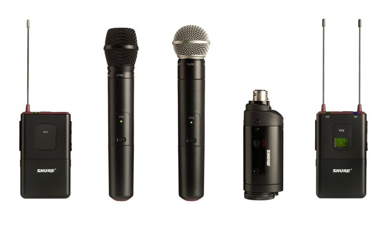
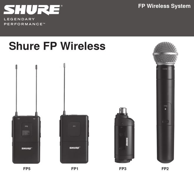
Featuring a comprehensive selection of system configurations with key wireless audio technologies and components, FP Wireless provides the ability to capture crystal-clear audio with confidence. With simple and flexible components, including a portable receiver and XLR plug-on transmitter, it has never been easier for audio to be captured in the demanding and dynamic videography and electronic field production (EFP) environments.
Features
- Audio Reference Companding for crystal-clear audio
- Automatic Frequency Selection locates an open frequency at the touch of a button
- Automatic Transmitter Setup instantly syncs the transmitter to the receiver frequency
- Up to 12 compatible systems simultaneously
- All components powered by 2 AA batteries – no power cord required
- Transmitter gain attenuation control manages input level
Furnished Accessories
Quickstart
Install Batteries

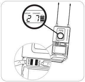
Power up the FP5 Receiver
Group scan for open frequencies
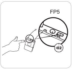
Power up the transmitter
![]()
Sync transmitter and receiver
![]()
FP5 Receiver
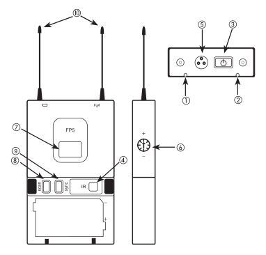
- Power LED

- RF LEDIlluminates when successfully synced to a transmitter (or manually tuned to a transmitter’s frequency)
- Power ButtonPress and hold to power on or off.
- Infrared (IR) portSends infrared beam to synchronize frequencies.
- TA3M JackUse with TA3F cable for audio out.
- Audio Output GainAdjust audio output level to devices such as cameras or recorders.
- LCD ScreenDisplays current settings for GROUP and CHANNEL and battery life.
- Scan ButtonGroup scan: Push and hold (3 sec.) to find an open group and channel.Channel scan: Push and release to find an open channel in the current group.
- Sync buttonAlign receiver and transmitter and press sync. Blue IR LED indicates successful sync.Note: Press sync and scan buttons to manually enter group and channel numbers
- AntennasTwo antennas for diversity reception.

Transmitter Controls and Connectors
![]()
- Indicator LED
- Power ButtonPress and hold to power on or off.
- Infrared (IR) PortReceives infrared beam to synchronize frequencies. When using multiple systems, only one transmitter IR port should be exposed at a time.
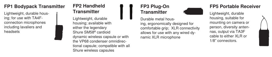
- 4-Pin Microphone Input JackUse with with a TA4F connector for a lavalier or headset microphone.
- Audio Input GainAdjusts audio level.
- XLR Connection (FP3 only)Plug into an XLR microphone or the output of an audio device.
- Audio Input Level Indicator (FP3 only)

Adjusting Gain
FP1 and FP3Perform a sound check. Use the audio gain control located on the side (FP1) or front (FP3) of the unit to adjust the gain up (+) or down (−) until desired level is reached.
FP3 only: Adjust so the audio input level indicator flickers yellow at peak sound levels.
FP2The handheld transmitter normally does not require adjustment and should be left at 0dB for most applications. Only use the –10dB setting for loud singing or other high SPL applications if there is noticable distortion.Access the gain adjustment switch by unscrewing the head of the microphone. Use the tip of a pen or a small screwdriver to move the switch:
0dB: For normal use.–10dB: Use only if audio distorts due to high SPL levels.
Single System Setup
- Perform a group scan:Press and hold the scan button for 3 seconds. After the scan completes, the new group and channel is automatically activated and saved.
- Synchronize the transmitter:Align the transmitter and receiver infrared (IR) ports and press the sync button.After a successful sync, the transmitter LED momentarily flashes and the blue RF LED illuminates.
Manual Group and Channel Selection (receiver only)
Important: Most single-system applications do not require manual group or channel settings–use an automatic frequency scan instead. However, it may be useful for some applications, such as to tune to and record audio directly from a microphone in a compatible wireless installation.
To set the group:
- Press the scan and sync buttons simultaneously. The GROUP display flashes.
- Press the sync button to change the group number.
- Press scan to accept the selected group.
- Press scan again to save and exit.
- If desired, perform a channel scan to select an open channel in that group.
To set the channel:
- Press the scan and sync buttons simultaneously. The GROUP display flashes.
- Press scan to move to the channel setting. The CHANNEL number flashes.
- Press the sync button to advance to the desired channel number.
- Press scan to save and exit.
Note: Remember to sync the transmitter to the receiver.
Multiple System Setup
Use the following steps to ensure the best performance when using multiple wireless systems at the same location.
- Turn all receivers on and all transmitters off.Note: Turn on any other digital equipment that could cause interference during the performance so it will be detected during the frequency scans in the following steps.
- Perform a group scan using the first receiver by pressing and holding the scan button for 3 seconds.
- Turn on the first transmitter and sync it to the receiver.
For each additional system:
- Manually set the group number to match the first receiver (see Manual Group and Channel Selection).
- Perform a channel scan by pressing the scan button.
- Sync the transmitter to the receiver.
Important: After syncing each transmitter, leave it on so that scans from the other receivers do not select that channel. Be sure only one transmitter IR port is exposed when synchronizing each system.
Automatic Frequency Scan
If you experience RF interference, switch to a new channel using the channel or group scan.
Channel scan: Press the scan button on the receiver. Switches to new channel in the same group.
Group scan: Press and hold the scan button for 3 seconds. Finds a new group and selects an open channel in that group. (Do not use in multiple system setups unless all systems are moved to the same group.)
Locking and Unlocking the Transmitter
Locking the transmitter prevents accidental changes during performances.
To lock the controls: With the transmitter off, hold the power button down until the green LED flashes (~5 seconds)
To unlock the controls: With the transmitter on, hold the power button down until the green LED flashes (~5 seconds)
Troubleshooting
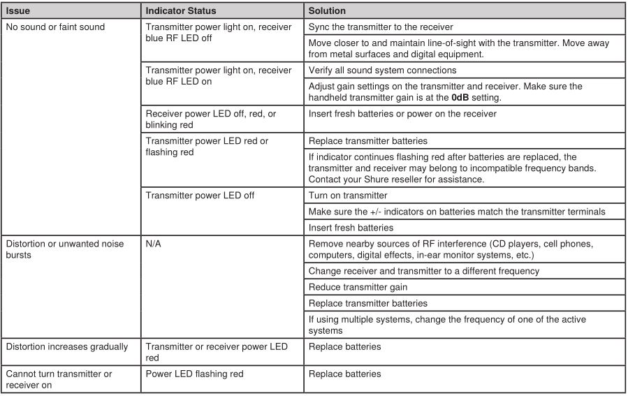
Tips for Improving System Performance
- Maintain a line-of-sight between transmitter and receiver
- Avoid proximity to metal surfaces and digital equipment that could cause RF interference, such as computers, cell phones, LCD screens, and other audio electronics.
Furnished Accessories
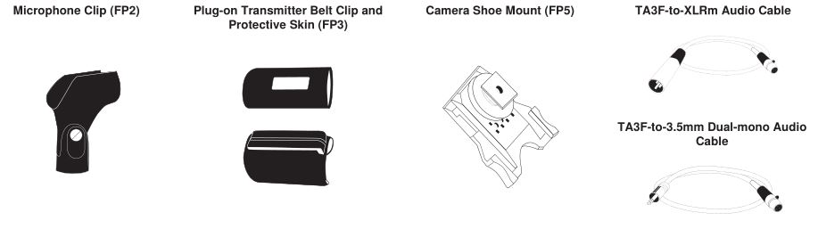
Microphone clip (FP2) _____ WA371Plug-on Transmitter belt clip and protective skin (FP3) _____ AFP301Camera Shoe Mount (FP5) _____ AFP511TA3F-to-XLRm audio cable _____ WA451TA3F-to-3.5mm dual-mono audio cable _____ WA461
Specifications

FP1

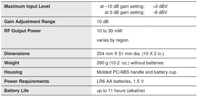
FP2
FP3

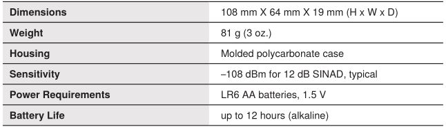
FP5
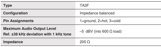
Audio Output
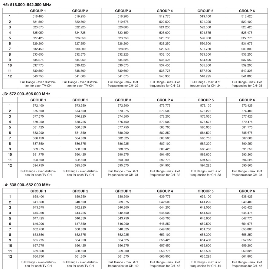
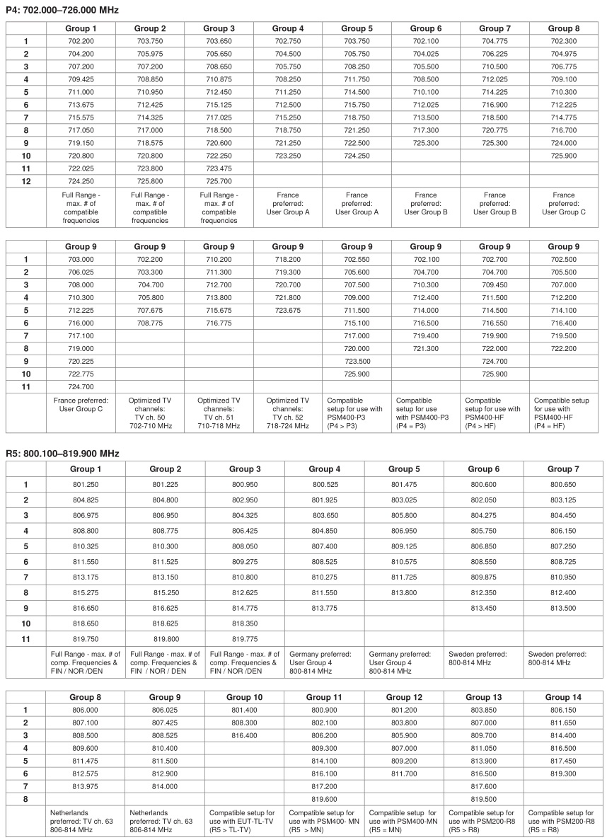
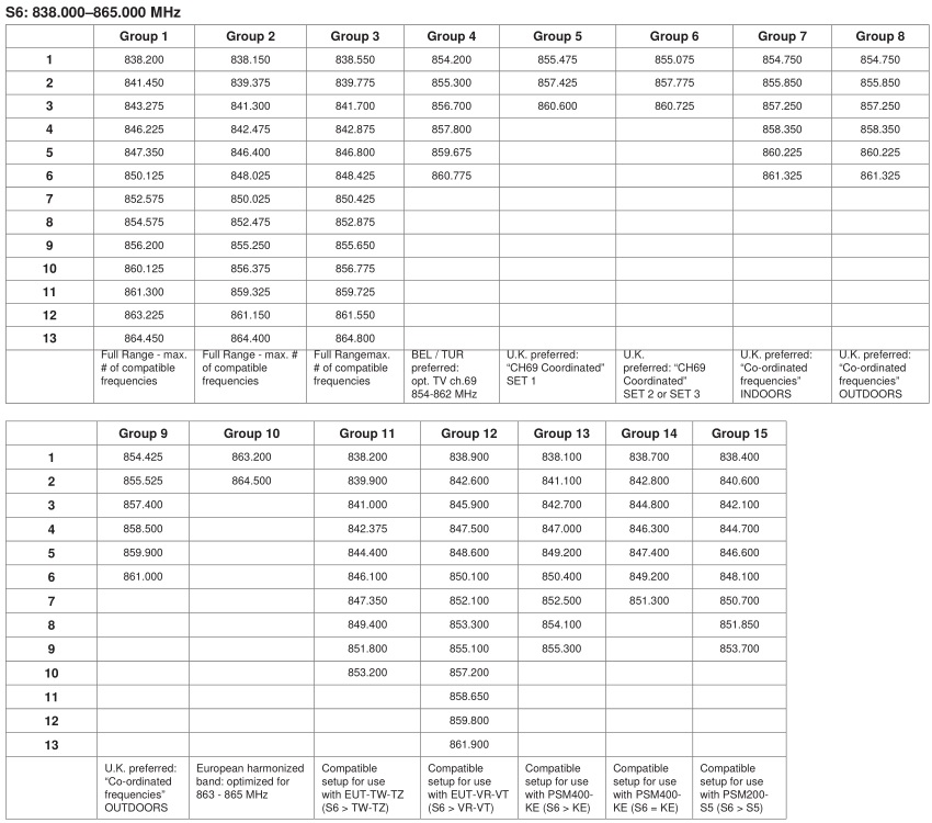
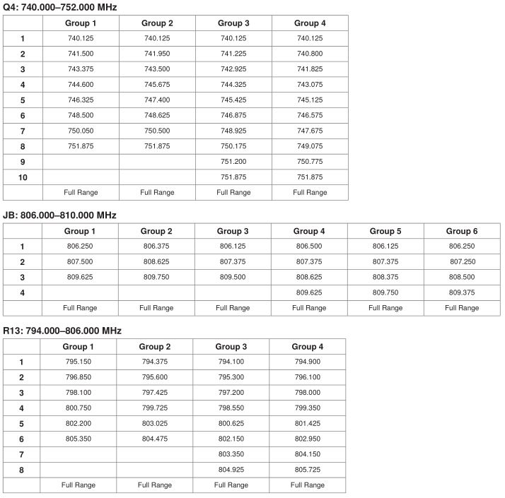
Frequency Range and Transmitter Output Power
![]()
NOTE: This Radio equipment is intended for use in musical professional entertainment and similar applications. This Radio apparatus may be capable of operating on some frequencies not authorized in your region. Please contact your national authority to obtain information on authorized frequencies and RF power levels for wireless microphone products.
Certifications
FP1, FP2, FP3, FP5This Class B digital apparatus complies with Canadian ICES-003.Meets requirements of the following standards: EN 300 422 Parts 1 and 2, EN 301 489 Parts 1 and 9, EN60065.Meets essential requirements of the following European Directives:
- R&TTE Directive 99/5/EC
- WEEE Directive 2002/96/EC, as amended by 2008/34/EC
- RoHS Directive 2002/95/EC, as amended by 2008/35/EC
Note: Please follow your regional recycling scheme for batteries and electronic waste
FP5Approved under the Declaration of Conformity (DoC) provision of FCC Part 15.Certified by IC in Canada under RSS-123 and RSS-102.IC: 616A-FP5L, 616A-FP5M, 616A-FP5A, 616A-FP5B, 616A-FP5C
LICENSING INFORMATIONLicensing: A ministerial license to operate this equipment may be required in certain areas. Consult your national authority for possible requirements. Changes or modifications not expressly approved by Shure Incorporated could void your authority to operate the equipment. Licensing of Shure wireless microphone equipment is the user’s responsibility, and licensability depends on the user’s classification and application, and on the selected frequency. Shure strongly urges the user to contact the appropriate telecommunications authority concerning proper licensing, and before choosing and ordering frequencies.
Note: EMC conformance testing is based on the use of supplied and recommended cable types. The use of other cable types may degrade EMC performance.
Changes or modifications not expressly approved by the manufacturer could void the user’s authority to operate the equipment.
![]()
WARNING: Danger of explosion if battery incorrectly replaced. Operate only with Shure compatible batteries.
![]()
WARNING: Battery packs shall not be exposed to excessive heat such as sunshine, fire, or the like.
FP1, FP2, FP3Type Accepted under FCC Parts 74.FCC: DD4FP3L, DD4FP3M, DD4FP3A, DD4FP3B, DD4FP3C, DD4SLX1G4, DD4SLX1G5, DD4SLX1, DD4SLX2G4, DD4SLX2G5, DD4SLX2.Certified by IC in Canada under RSS-123 and RSS-102.IC: 616A-FP3L, 616A-FP3M, 616A-FP3A, 616A-FP3B, 616A-FP3C, 616A-SLX1G4, 616A-SLX1G5, 616A-SLX1, 616A-SLX2G4, 616A-SLX2G5, 616A-SLX2.This device complies with Industry Canada licence-exempt RSS standard(s). Operation of this device is subject to the following two conditions: (1) this device may not cause interference, and (2) this device must accept any interference, including interference that may cause undesired operation of the device.
The CE Declaration of Conformity can be obtained from Shure Incorporated or any of its European representatives. For contact information please visit www.shure.com
The CE Declaration of Conformity can be obtained from: www.shure.com/europe/compliance
Authorized European representative:Shure Europe GmbHHeadquarters Europe, Middle East & AfricaDepartment: EMEA ApprovalJakob-Dieffenbacher-Str. 1275031 Eppingen, GermanyPhone: 49-7262-92 49 0Fax: 49-7262-92 49 11 4Email: [email protected]
Information to the userThis equipment has been tested and found to comply with the limits for a Class B digital device, pursuant to Part 15 of the FCC Rules. These limits are designed to provide reasonable protection against harmful interference in a residential installation. This equipment generates uses and can radiate radio frequency energy and, if not installed and used in accordance with the instructions, may cause harmful interference to radio communications. However, there is no guarantee that interference will not occur in a particular installation. If this equipment does cause harmful interference to radio or television reception, which can be determined by turning the equipment off and on, the user is encouraged to try to correct the interference by one or more of the following measures:
- Reorient or relocate the receiving antenna.
- Increase the separation between the equipment and the receiver.
- Connect the equipment to an outlet on a circuit different from that to which the receiver is connected.
- Consult the dealer or an experienced radio/TV technician for help.
Frequency Ranges
![]()
United States, Canada, Latin America, Caribbean:Shure Incorporated5800 West Touhy AvenueNiles, IL 60714-4608 USAPhone: 847-600-2000Fax: 847-600-1212 (USA)Fax: 847-600-6446Email: [email protected]
Europe, Middle East, Africa:Shure Europe GmbHJakob-Dieffenbacher-Str. 12,75031 Eppingen, GermanyPhone: 49-7262-92490Fax: 49-7262-9249114Email: [email protected]
Asia, Pacific:Shure Asia Limited22/F, 625 King’s RoadNorth Point, Island EastHong KongPhone: 852-2893-4290Fax: 852-2893-4055Email: [email protected]
www.shure.com©2012 Shure Incorporated
Shure FP Wireless System User Manual – Shure FP Wireless System User Manual –
[xyz-ips snippet=”download-snippet”]