
PLEASE READ THESE INSTRUCTIONS BEFORE INSTALLATION
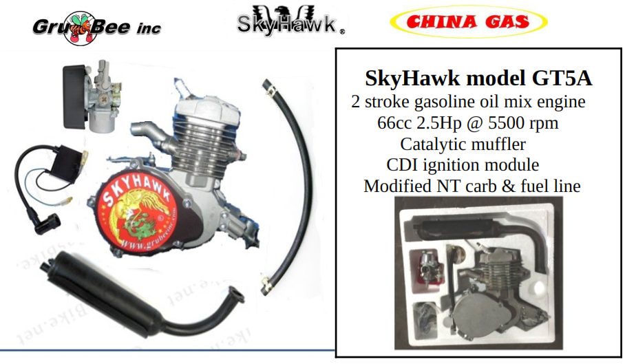
YuanDong 2015 EPA Compliant Engine
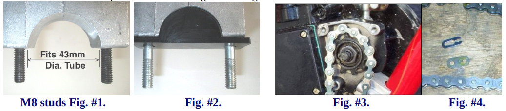
Step #1. Record the following information and save for warranty purposes and for future repair parts service.1. Record; Engine serial number found on the right side of the engine crankcase,2. Record: Gt5A Engine model and Date of manufacture found on the left side metal ID plate;Note: This engine has no OEM application nor is it intended to be used for any OEM engine replacement. It is for “DIY” ( Do it Yourself ) individual hobby enthuses application: The End User or the Installer becomes the manufacture and assumes all laws of the land including any product liability. Do not use or buy this product if you expect otherwise. Mechanical aptitude and working ability is required to perform this installation. Many “do it yourself” backyard mechanics will find this project rewarding. A love of small engines and mechanical engineering experience is the only required catalyst.These engines conform to 2015 EPA Small Engine Spark Ignition emission regulation 40CFR1054. If used on a bicycle application for power assist the combined weight of this engine and the donor bicycle cannot exceed 20kg. Failure to do so violates the 1970 Clean Air Act. If used on hand held or stationary power equipment said weight limits do not apply. Remember, a quality installation and daily maintenance is paramount to safe usage and long term satisfaction. You may find many uses for this engine such as power for a stationary machine or for other off road machine application. Have fun and good luck on your motorized project. Happy trails to you from Gru-Bee / China GAS and YuanDong factory:Mounting the Gt5A Engine:1. The engine mounts best in a “Vee” type frame. It is a good idea to make sure all 4 engine studs are securely bottomed out in the engine before mounting. M8 studs are on the front side and M6 studs are at the 32mm dia. opening rear slide block. Use a double nut “Jam Nut” procedure to tighten studs if no Allen head studs are found.. Your engine will fit V frame tubes up to 40 to 50 mm dia. front mount seeFig. #1. and 28 to 34mm dia. rear mt. If mounting engine on a flat surface you may want to use a rubber shock mounts which are available from your dealer p/n’s RB#43 and RB#32. These rubber shock mounts fit over the studs and fill up the curved openings. See Fig. #2. Excessive engine tilt can cause the drive chain to hit the drive cover and your engine to not run properly due to improper float level in the carb.. It is best to have the 415 drive chain be as horizontal as possible with no more than 15 degrees engine tilt. After the desired engine location is determined mount the engine to frame. Appling LocTite thread lock to avoid premature loosening due to engine vibration. Note: All threads are metric.
2. Remove left rear cover plate from engine. This is the plate next to and under the clutch swing arm.3 The engine 10T drive sprocket accepts 415 chain only. Standard 410 or ½”x 3/8 Bike chain won’t fit.4. Use the supplied spark-plug wrench to turn the engine over so you can feed the chain around the 10T.5. Fit chain, by removing excess links to assure proper length. Be sure master link connection rides on the inboard side of the primary drive sprocket or interference of link and sprocket can occur. Proper chain length is when top chain has ¼ inch to ½” deflection with the bottom side of the chain loop tight.6. Mount TCI ignition module, close enough to attach coil wire to spark plug. Mount as far away from exhaust pipe as possible to avoid heat damage to semiconductors.7. Attach TCI wires to same identical color coded wires coming from engine magneto.8. Install an Engine Kill Switch Wires to the empty terminal holes on the TCI / magneto wire ends.. This will ground ignition and stop the engine when the kill button is activated.9. Route all wires away from engine exhaust heat. Secure wires with a plastic tie straps.*!WARNING! Operation of engine without stop or kill switch installed could result in personal injury if an emergency stop is required! The only alternate non recommended way of killing the engine is by releasing the clutch lever with engine at slowest idle and apply a driven wheel brake.Warning: In order to maintain engine warranty and to stay within engine emission standards set forth by EPA do not change the catalytic muffler or special carburetor to a non- compliant replacement. Replace with original OEM SkyHawk parts only. Clutch cable installation and adjustment:A) Install a stainless steel clutch cable barrel end into lever slot hole.B) Squirt light oil down the cable sleeve: Route clutch cable through the ball-mount on engine with the big spring around the cable jacket and ahead of the ball mount. The big spring serves as a cable heat shield.C) Insert cable wire through small spring and route through clutch arm and attach brass cable-end and screw. Adjust cable tension to allow very slight play in arm with clutch lever in the released position. Activate hand lever a few times, and check clutch arm for slight free play: About 1/16” engine clutch arm free play is required with the handle bar lever in the released in what is called clutch engaged position or the engine will fail to start if cable is too loose or if too tight. Re-adjust as required.D) Basics of clutch operation: The hand lever pulls the cable that moves the engine clutch arm. In turn the clutch arm pushes a rod that pushes the clutch plate out. ( similar to a car clutch.) Releasing the hand lever engages the clutch and provides engine torque to the drive chain or to start the engine. The clutch friction allows engine to start when the driven wheel is rotated and also transmits engine torque to the drive chain.
play with handle bar lever released which would be in the clutch engaged position.Be sure to check all nuts and bolts on Engine and end of muffler for proper tightness.
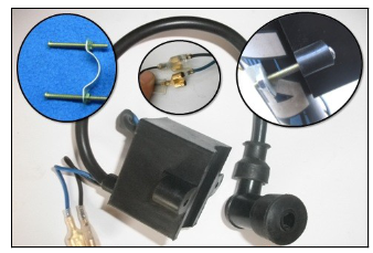 Install TCI module as far away from engine heat as possible.

First install Blue & Black wires from engine magneto to same color CDI wires.Warning: Do not hook up backwards or damage to CDI module will occur.1. Next install kill switch wire bullets into the 2 remaining open holes of the 2 CDI wire terminals. Color code not important. These 2 wires cannot be hooked up backwards:2. Push the clear rubber protectors over the twin connections and tape with black electrical tape.3. The remaining white wire from the engine, if present, is not needed unless you want to run a small wattage 6V headlight but it’s not recommended, as it will rob engine ignition power. All 2015 GT5A engines have no white wires.4. To keep water out of the magneto box use a heat shrink tube over the wire sheathing and seal exit plug connection with RTV.
 Engine firing timing is not adjustable; Position of the p/m rotor is fixed to ensure correct 25-degree BTDC timing. If engine does not fire at startup check all connections. Check if kill switch has an unwanted ground. Make sure magneto has a good ground and not insulated by varnish.If installing this engine on a bicycle EPA requires that the total combined vehicle weight with engine and accouterments cannot exceed 20kg. Failure to meet this weight requirement means you are in violation of the 1970 Clean Air Act so stated at www.epa.gov. Fig. #4. is an example of an Alum.700c bike that allows total weight to be less than 20Kg.


The small stop on the cable wire end slides through the long groove on the slide valve. Early slide valves were made of brass and later ones are made of black plastic. Beware that there are 2 different NT Carbs. The best one to use for racing is the NT carb with a 14.95mm in dia. slide valve but to meet EPA exhaust standards we have to use a special modified NT carb. with a 14.5mm dia. slide valve. ( Note component positions in pictures; Needle clip is factory set in second slot and is not adjustable: ) The spring is placed inside the cylinder slide and is compressed when the throttle is twisted. Be sure it is seated all the way inside the cylinder. The spring then forces the throttle to return. For this to work properly the throttle must twist freely in both directions prior to the cable being installed.A) Install a lever or twist-grip throttle. It never hurts to add a few drops of light wt. oil to let trickle down the cable inside the full length of sheathing.B) After installing cable inside the carburetor you are ready to mount it on the engine intake tube and tighten clamp screw. Mount engine so carburetor sets as level as possible.Fuel Tank installation
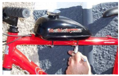 A) If the engine is to be installed on a bicycle a steel tank must be used with a EPA-approved fuel line.
IMPORTANT: PLEASE READ THIS: Gas and Oil Mixture Fuel Ratio:Engine break-in or wear–in is most important; The engine is a 2 cycle design, therefore, a gasoline/oil mixture is necessary. It is recommended that EcoTech brand synthetic oil be used at a 50 to 1 ratio but only after engine break-in has been accomplished. During the break-in period, (1 tank of fuel or 4 to 6 hrs ), the mix should be 25 parts gasoline to 1 part oil. After the break-in period, the ratio can increased to 50 parts gasoline to 1 part oil. *NOTE: The recommended oil to ensure your engine warranty is ECOTECH Synthetic 2 Stroke Engine Oil and can be purchased from your Skyhawk engine dealer.. st!WARNING! Remember safety first: Wipe up any spilled fuel. NEVER fuel a hot engine or smoke while fueling. This could result in sudden fire, personal injury.
MAINTENANCE SECTION
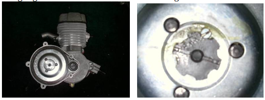
# 1. How to Adjust Clutch if signs of slipping or squealing are encountered :A) Disengage clutch by pulling handle bar clutch lever inward and lock into catch lock.B) Remove right side engine clutch cover and remove small locking screw on center *Clutch Adjust Nut.C) Pull clutch arm on left rear engine inward. Back off *Clutch Adjust Nut ¼ turn counterclockwise.D) Release clutch lever and check for slight clutch arm 1/16” free-play on opposite side of engine. Readjust *Clutch Adjust Nut as required to get required 1/6” clutch arm free play.E) Tighten *Clutch Adjust Nut on clutch plate clockwise until just snug.F) Then re-install small locking screw in outer edge of *Clutch Adjust Nut .G) Good idea to place a small gob of grease at gear mesh area. Use grease sparingly! Then replace cover.H) Squirt light grade oil down clutch cable sheathing to reduce friction and make for easy lever pull.
2. CarburetorDepending on dusty riding conditions, clean air filter every 5 to 20 hours of operation by removing the filter cover to access the screen and element. Wash element with a degreasing agent such as Simple Green™ or Purple Stuff™. Be sure element is completely dry before re- ssembly. IMPORTANT: If engine runs poorly clean tank shut off value filter and if that is not the problem check for a clogged muffler. If engine is left setting for long periods of time ie; over the winter months drain the carb so gumming does not occur.
MAINTENANCE SECTION Continued:
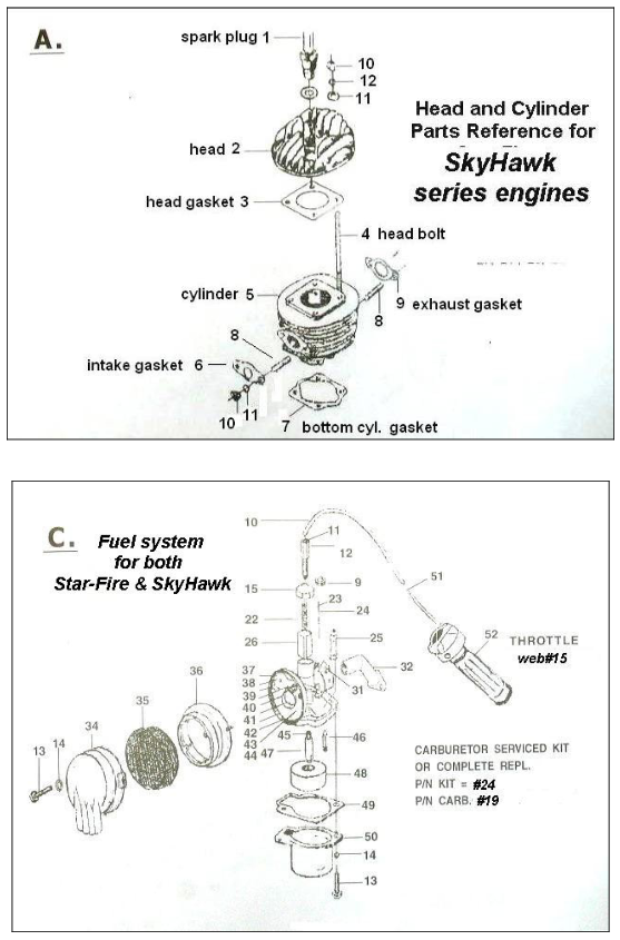
#3. 3 pt. Spark PlugRemove spark plug and inspect for excess carbon build up. Clean, re-gap to .0.036” of an inch if necessary. Check plug after every 20 hours of operation. New 3pt. spark plugs are available from your selling dealer. Be careful using aftermarket spark plugs as heat range and threads differ greatly. An extra plug is included in your kit: When replacing the spark plug it’s best to use a 3 point electrode spark plug P/N Z4JC to ensure total combustion. ( Ask your selling dealer for it by part number. )#4. Exhaust systemAfter 50 hours of operation check exhaust pipe for excessive oil and carbon build-up. If muffler is clogged your dealer has a replacement. Make sure attaching nuts are tight and no exhaust leaks are occurring. Be sure to use supplied support strap to secure exhaust muffler to a solid anchor point on bike frame or engine.A) To remove inside catalytic exhaust insert loosen the retaining screw on end cap and remove.B) Pull cap and baffle out of pipe. Note: Some catalytic inserts are welded in and cannot be removed. If you need a replacement muffler contact your dealer. Muffler has an air shield welded on the outside of muffler again per EPA test rulings. This insures a hot run so catalysis can better clean the exhaust.C) Clean with degreaser, rinse and dry. Re-assemble: File muffler attach flange to have smooth flat surface.D) Always use a new exhasut gasket and good idea to use double nuts on muffler attach studs;*NOTE: Excessive periods of low speed operation, idling or leaving fuel petcock in the “on” position during shut down periods may cause the muffler to become clogged with unburned fuel.#5. Drive Chain: Use a 410 chain or a 415 chain.Find the center and push downward on the top of chain while measuring the deflection.A) Tighten chain if deflection is more than ½ inch.#6. Head Bolts Tighten all fasteners after each five hours of operation. Most important to check Cylinder head bolts : Tighten in an X pattern to 10 ft/lb using a torque wrench. A two piece cylinder and head design engine requires head bolts be kept tight. Important: Check head bolts before each and every long ride, vibration can cause them to loosen and blow a head gasket. Caution: Do not over torque or head bolts may break off. ( Twisted or broken head bolts due to over-tightening is not covered by warranty. )#7. Right side gears: Remove cover plate and keep small amount of heavy grease on gear train. Do not over grease as excess may adversely affect clutch operation. Regular greasing if required will help reduce gear wear and keep gear train quiet.#8. Left side drive: Routinely pack grease in the shaft hole behind 10T sprocket and also in cover hole. This will also help reduce noise.

Gear & Sprocket Puller and Spark Plug wrench. These tools are available from your selling dealer. Use the gear puller to remove 10T drive sprocket and B5 gear on right side of engine. ENGINE STARTING & OPERATION PROCEDUREIMPORTANT: PLEASE READ THIS: Gas and Oil Mixture for Fuel ratioThe engine is a 2 cycle design, therefore, a gasoline/oil mixture is necessary. It is recommended that EcoTech brand synthetic oil be used at a 50 to 1 ratio but only after engine break-in has been accomplished. During the break-in period, (1tank of fuel or 6 hrs ), the mix should be 25 parts gasoline to 1 part oil. After the break-in period, the ratio can increased to 50 parts gasoline to 1 part oil. *NOTE: The recommended oil to ensure your engine warranty is ECOTECH Synthetic 2 Stroke Engine Oil and can be purchased from your Skyhawk engine dealer.. st!WARNING! Remember safety first: Wipe up any spilled fuel. NEVER fuel a hot engine or light a cigarette while fueling. This could result in sudden fire, personal injury. Always move your motorized bike at least 10 feet from any fueling area before attempting to start it. Never leave the tank fuel cap off after fueling as rainwater will contaminate the fuel and cause engine failure.Step #1. After filling tank with the correct oil/gas mix open the tank fuel valve. Fuel line is in the open position when the small lever is pointed down. Move choke lever to the on position. This is the small lever at the end of the choke cable All the way Up the choke is on. All the way Down the choke is off. Move progressively downward to off position during engine warm-up period.Engine Starting procedure for Lever Clutch Models:1. Pull the clutch lever inward, to disengage the engine..2. Let out the clutch lever all the way out and turn the driven wheel to turn the engine over.3. A rope pull can be installed on the right side of the engine if a driven wheel cannot be turned..4. Twist throttle to increase speed, reverse twist throttle to decrease speed.5. Adjust choke to the smoothest engine running position.7. After warm up push choke lever all the way down. If engine races too fast, or too slow, pull clutch lever to lock position and adjust engine rpm.8. If the rpm needs adjusting, turn the idle adjust screw (left side of carburetor) in or out slowly to obtain the proper idle speed of about 1800 rpm +/- 100 rpmTo correctly break the engine in run at no more than ½ to ¾ open throttle for 2 to 4 hours. Engine will have 15 to 20% more power after break in.9. To stop the engine, push Kill switch and turn off gas valve at tank. Turning off the gas will prevent fuel from being siphoned from tank. Warning Note: Never leave the tank gas valve in “open” position” when engine is not running or the bike is in storage.10. Warning Note: Engine lock up or piston seizure due to improper gas / oil mixture will not be covered by factory warranty. This the responsibility of the owner/operator to make sure the gas and oil is mixed correctly. It is recommended that a temp. gauge be installed with sensing wire connected to an engine head bolt. Should the engine temp. approach 250C let idle for 1 minute and shut off to cool. Shutting off a super hot engine suddenly that has ran past the red line can seize the piston to the cylinder wall.
YuanDong SkyHawk mfg.> ENGINE WARRANTY POLICY:
Proper use and maintenance is required for the continued enjoyment of your Bike Engine. This product has been manufactured to strict quality control standards. For product warranty policy contact your selling dealer. Basic engine warranty is 90 days; Emmission controlled ites carry a longer 2 year warranty or 50 hrs which ever occurs first. Warranty approval is subject to dealer inspection and only the defective part or parts will be replaced, not the complete kit or engine. Only the defective part or parts should be returned to the selling dealer for warranty replacement consideration. Your dealer may require you to obtain his authorization first before returning defective parts. Include engie serial # , description and picture of failure with as many details as possible. Note: Seized pistons due to improper gas / oil mix or shipping damage due to carrier neglect is no a warranty. Using gas with more than 10% ethanol causing engine to run hot and seize up is no warranty. Hooking up CDI wires backward causing a failure is no a warranty! Observe color code when installing these wires from engine to the ignition module. Use EcoTech oil to ensure warranty.


SkyHawk Model GT5A YuanDong EPA Compliant Engine Installation Manual – SkyHawk Model GT5A YuanDong EPA Compliant Engine Installation Manual –
[xyz-ips snippet=”download-snippet”]