SLAMTEC A2M8 RPLIDAR A2 Low Cost 360
Degree Laser Range Scanner Instructions
www.slamtec.comShanghai Slamtec. Co., Ltd
2021-04-02 rev.2.6
Introduction

The RPLIDAR A2 is the latest generation low cost 360 degree 2D laser scanner (LIDAR) solution developed by SLAMTEC. It can take up to 8000 samples of laser ranging per second with high rotation speed. And equipped with SLAMTEC patented OPTMAG technology, it breakouts the life limitation of traditional LIDAR system so as to work stably for a long time.
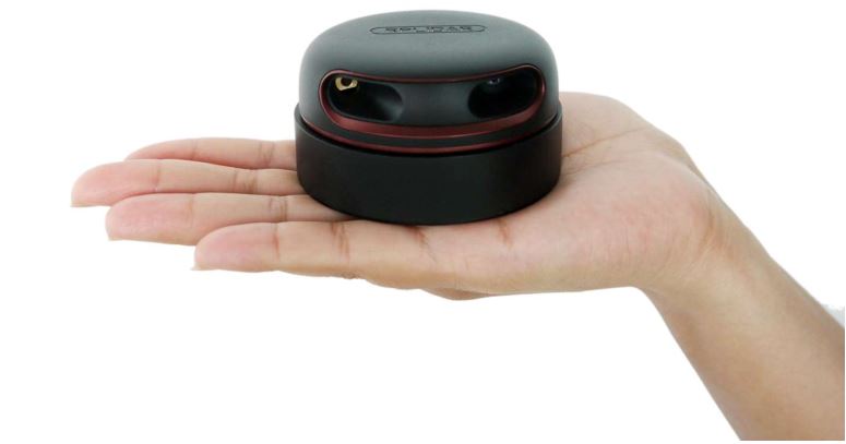
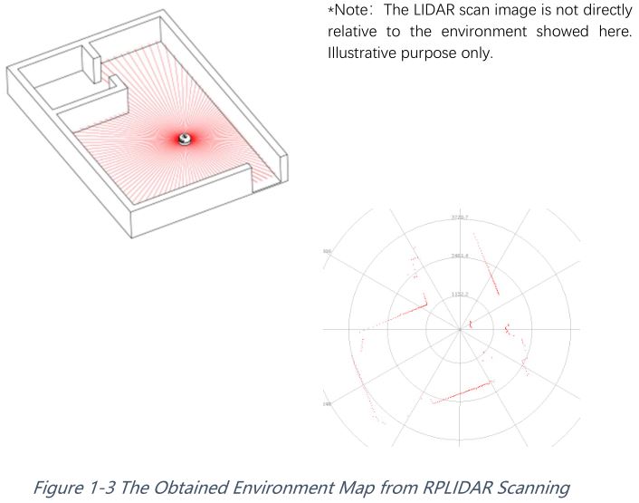
RPLIDAR A2M8 is the enhanced version of 2D laser range scanner(LIDAR).The system can perform 2D 360 degree scan within a 12-meter range. The generated 2D point cloud data can be used in mapping, localization and object/environment modeling.
The typical scanning frequency of the RPLIDAR A2 is 10hz (600rpm). Under this condition, the resolution will be 0.45°. And the actual scanning frequency can be freely adjusted within the 5-15hz range according to the requirements of users.
The RPLIDAR A2 adopts the low-cost laser triangulation measurement system developed by SLAMTEC, which makes the RPLIDAR A2 has excellent performance in all kinds of indoor environment and outdoor environment without direct sunlight exposure. Meanwhile, before leaving the factory, every RPLIDAR A2 has passed the strict testing to ensure the laser output power meet the standards of FDA Class I.
System connection
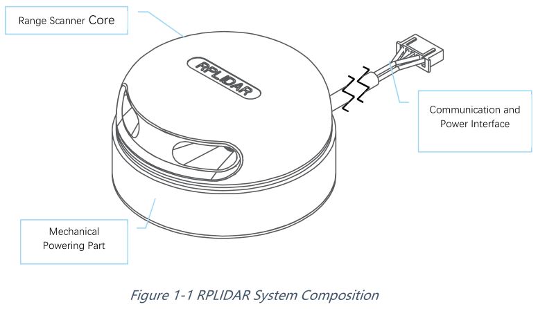
The RPLIDAR A2 consists of a range scanner core and the mechanical powering part which makes the core rotate at a high speed. When it functions normally, the scanner will rotate and scan clockwise. And users can get the range scan data via the communication interface of the RPLIDAR and control the start, stop and rotating speed of the rotate motor via PWM.
The RPLIDAR A2 comes with a rotation speed detection and adaptive system. The system will adjust the angular resolution automatically according to the actual rotating speed. And there is no need to provide complicated power system for RPLIDAR. In this way, the simple power supply saves the BOM cost. If the actual speed of the RPLIDAR is required, the host system can get the related data via communication interface.
The detailed specification about power and communication interface can be found in the following sections.
Mechanism
The RPLIDAR A2 is based on laser triangulation ranging principle and adopts the high-speed vision acquisition and processing hardware developed by SLAMTEC. The system ranges more than 8000 times per second.
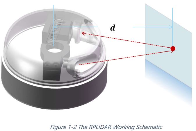
During every ranging process, the RPLIDAR emits modulated infrared laser signal and the laser signal is then reflected by the object to be detected. The returning signal is then sampled by vision acquisition system in RPLIDAR and the DSP embedded in RPLIDAR starts processing the sample data and outputs distance value and angle value between object and RPLIDAR via communication interface. When drove by the motor system, the range scanner core will rotate clockwise and perform the 360-degree scan for the current environment.
 Safety and Scope
The RPLIDAR A2 system uses a low power infrared laser as its light source, and drives it by using modulated pulse. The laser emits light in a very short time frame which can ensure its safety to human and pet, and it reaches Class I laser safety standard. Complies with 21 CFR 1040.10 and 1040.11 except for deviations pursuant to Laser Notice No. 50, dated June 24, 2007.
Caution: Use of controls or adjustments or performance of procedures other than those specified herein may result in hazardous radiation exposure.
The modulated laser can effectively avoid the interference from ambient light and sunlight during ranging scanning process, which makes RPLIDAR work excellent in all kinds of indoor environment and outdoor environment without sunlight.
Data Output
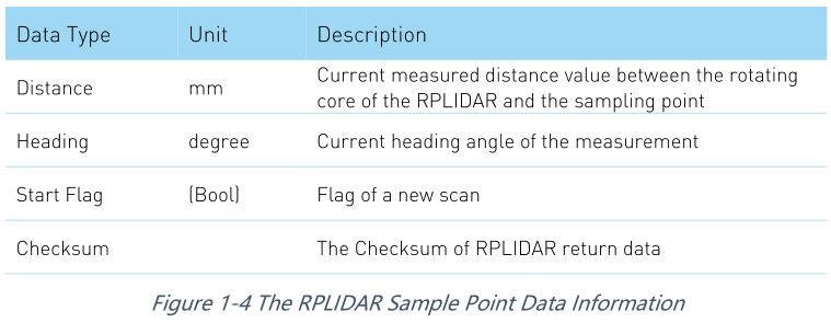
During the working process, the RPLIDAR will output the sampling data via the communication interface. And each sample point data contains the information in the following table. If you need detailed data format and communication protocol, please contact SLAMTEC.
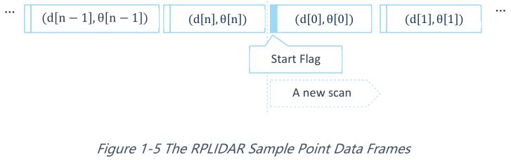
The RPLIDAR outputs sampling data continuously and it contains the sample point data frames in the above figure. Host systems can configure output format and stop RPLIDAR by sending stop command. For detailed operations please contact SLAMTEC.
High Speed Sampling Protocol and Compatibility
The RPLIDAR A2 adopts the newly extended high speed sampling protocol for outputting the 8000 times per second laser range scan data. Users are required to update the matched SDK or modify the original driver and use the new protocol for the 8000 times per second mode of RPLIDAR A2. Please check the related protocol documents for details.
Application Scenarios
The RPLIDAR can be used in the following application scenarios:
- General robot navigation and localization
- Environment scanning and 3D re-modeling
- Service robot or industrial robot working for long hours
- Home service /cleaning robot navigation and localization
- General simultaneous localization and mapping (SLAM)
- Smart toy’s localization and obstacle avoidance
Specification
Measurement Performance
For Model A2M8 Only
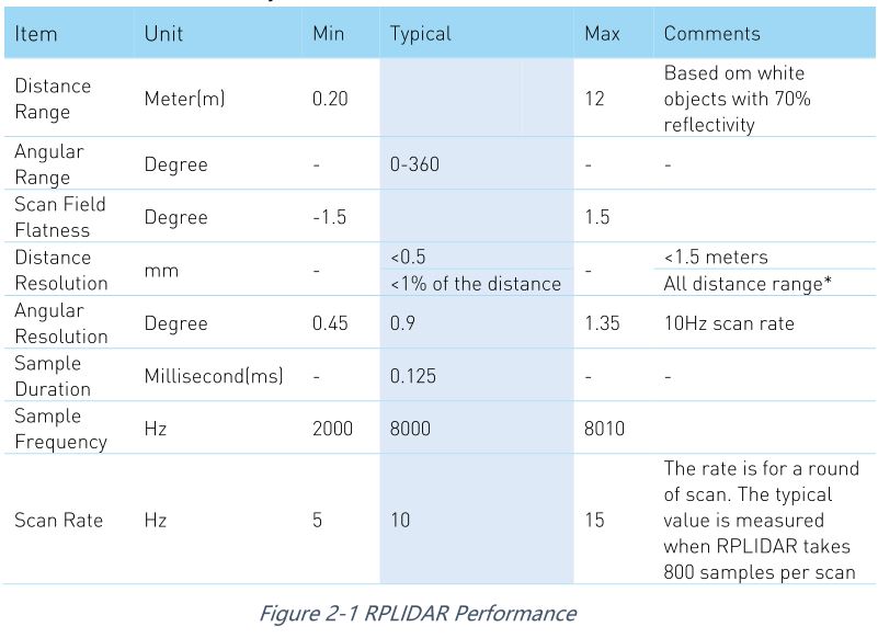
Note: the triangulation range system resolution changes along with distance.
Laser Power Specification
For Model A2M8 Only
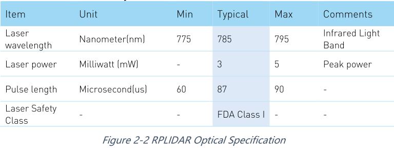
Note: the laser power listed above is the peak power and the actual average power is much lower than the value.
Optical Window
To make the RPLIDAR A2 working normally, please ensure proper space to be left for its emitting and receiving laser lights when designing the host system. The obscuring of the host system for the ranging window will impact the performance and resolution of RPLIDAR A2. If you need cover the RPLIDAR A2 with translucent materials or have other special needs, please contact SLAMTEC about the feasibility.
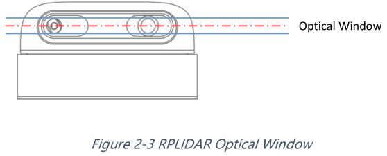
You can check the Mechanical Dimensions chapter for detailed window dimensions.
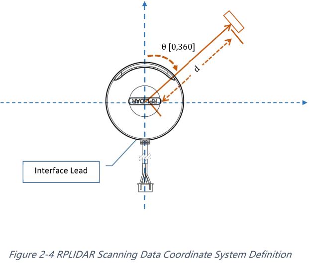
Coordinate System Definition of Scanning Data
The RPLIDAR A2 adopts left-handed coordinate system. The dead zone ahead of the sensors is the x axis of the coordinate system; the origin is the rotating center of the range scanner core. The rotation angle increases as rotating clockwise. The detailed definition is shown in the following figure:
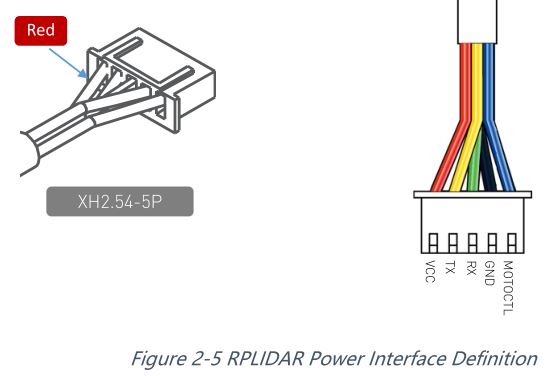
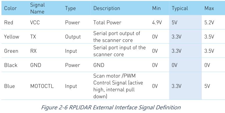
Communication interface
The RPLIDAR A2 uses separate 5V DC power for powering the range scanner core and the motor system. And the standard RPLIDAR A2 uses XH2.54-5P male socket. Detailed interface definition is shown in the following figure:
Power Supply Interface
RPLIDAR A2 takes the only external power to power the range scanner core and the motor system which make the core rotate. To make the RPLIDAR A2 work normally, the host system needs to ensure the output of the power and meet its requirements of the power supply ripple.
For Model A2M8 Only
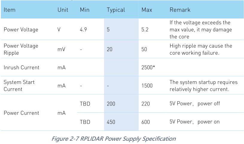
Note: When the lidar is connected to the power supply, there is a process of charging the input capacitor. The maximum transient current of charging can reach 2500mA. After stable operation, the working current does not exceed 600mA.
Data communication interface
The RPLIDAR A2 takes the 3.3V-TTL serial port (UART) as the communication interface. The table below shows the transmission speed and the protocol standard.
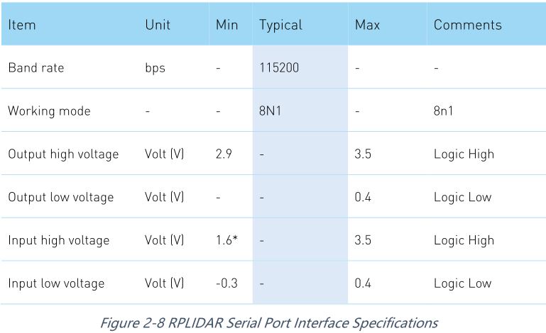
Note: the RX input signal of A2M4 is current control type. In order to ensure the reliable signal identification inside the system, the actual control node voltage of this pin will not be lower than 1.6v.
Scanner Motor Control
The RPLIDAR A2 is embedded with a motor driver which has speed tuning feature. Users can control the start, the stop and the rotating speed for the motor via MOTOCTL in the interface. MOTOCTL can be supplied using PWM signal with special frequency and duty cycle, and in this mode, the rotating speed is decided by the duty cycle of the input MOTOCTL PWM Signal.
The following table describes the requirement for the input PWM signal of MOTOCTL:

Note: the typical value is tested when the scanner rotating frequency is 10Hz. With the same rotating speed, the PWM duty cycle of every RILIDAR A2 may vary slightly. If a precise rotating speed is required, users can perform a closed-loop control.
If the host system only need to control the start and stop of the motor, please use the direct current signal in high level and low level to drive MOTOCTL. Under this condition, when the MOTOCTL is the low level signal, the RPLIDAR A2 will stop rotating and scanning; when the MOTOCTL is the high level signal, the RPLIDAR A2 will rotated at the highest speed.
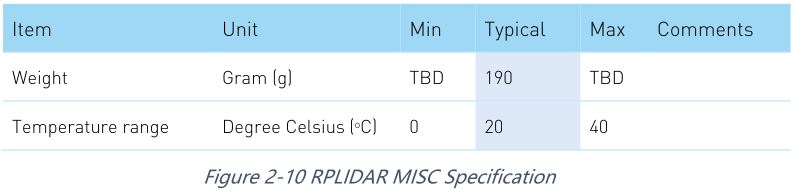
MISC
For Model A2M8 Only
Self-protection and Status Detection
To ensure the laser of RPLIDAR always working in the safety range (<3mW) and avoid any other damage caused by device, the RPLIDAR comes with laser power detection and sensor healthy check feature. It will shut down the laser and stop working automatically when any of the following errors has been detected.
- Laser transmit power exceeds limited value
- Laser cannot power on normally
- Scan speed of Laser scanner system is unstable
- Scan speed of Laser scanner system is too slow
- Laser signal sensor works abnormally
The host systems can check the status of the RPLIDAR via the communication interface and restart the RPLIDAR to try to recover work from error.
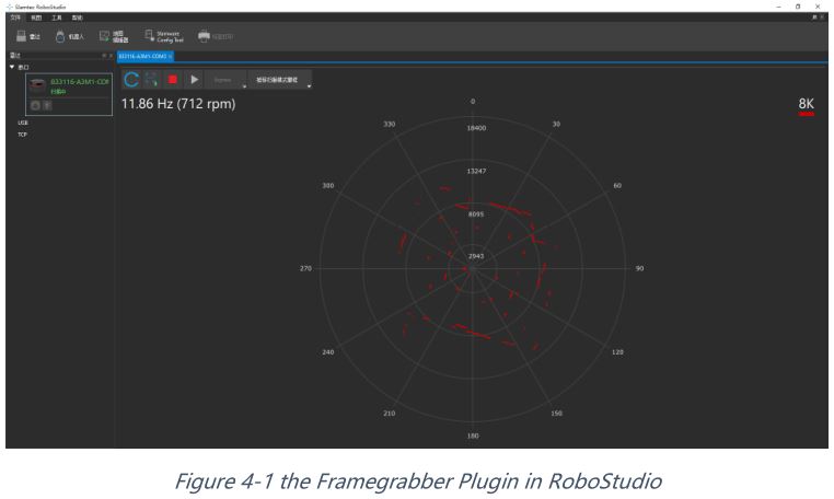
SDK and Support
To facilitate the usage of RPLIDAR A2M8 in the product development and speed up the development cycle for users, SLAMTEC has provided the Framegrabber plugin in RoboStudio for testing and debugging as well as the SDK available under Windows, x86 Linux and Arm Linux. Please contact SLAMTEC for detail information.
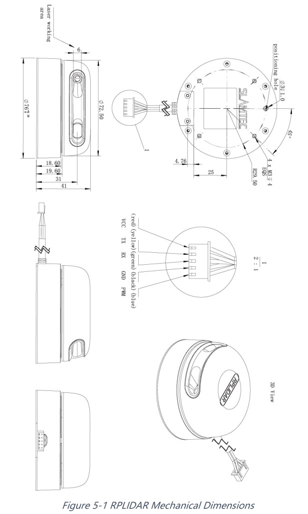
Mechanical Dimensions
The mechanical dimensions of the RPLIDAR A2 are shown as below:
Note: the 4 M3 screws in the bottom should be no longer than 4mm, or the internal module would be damaged.
Revision history
 report this ad
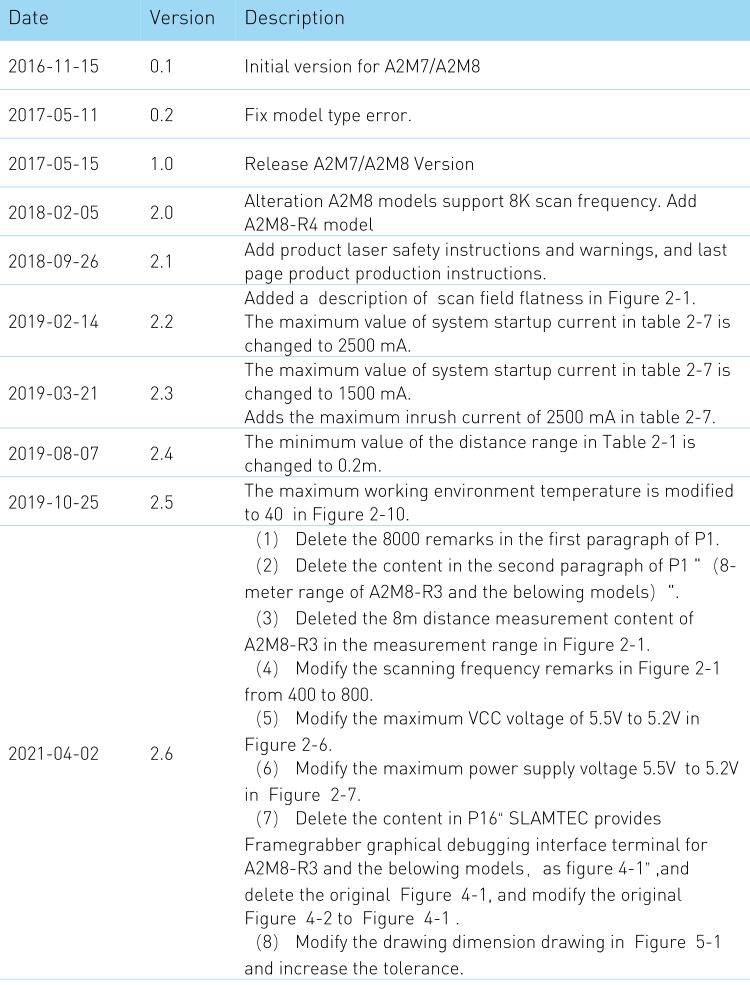
Manufacturer: SHANGHAI SLAMTEC CO., LTD.Address: D-501 Shengyin Tower, 666 Shengxia Rd., Shanghai, ChinaMade in China
Copyright (c) 2009-2013 RoboPeak TeamCopyright (c) 2013-2017 Shanghai Slamtec Co., Ltd.
References
[xyz-ips snippet=”download-snippet”]