SLI 820A Enforcer Factory Keyless Entry Alarm
 Adapter Security System User Manual
NOTICE
The information and specifications printed in this manual are current at the time of publication. However, the SECO-LARM policy is one of continual development and improvement. For this reason, SECO-LARM reserves the right to change specifications without notice. SECO-LARM is also not responsible for misprints or typographical errors.
Copyright ©2002 SECO-LARM U.S.A., Inc. All rights reserved. This material may not be reproduced or copied, in whole or in part, without the written permission of SECO-LARM. This vehicle security system is protected by patents in the U.S.A., Great Britain, Germany, Hungary, Taiwan, China, Japan, and Korea. Other U.S.A. and international patents are pending.
GENERAL CONSIDERATIONS
IMPORTANT: THIS ALARM IS INTENDED FOR INSTALLATION BY QUALIFIED PROFESSIONALS ONLY.READ BOTH THIS MANUAL AND THE OWNERS MANUAL COMPLETELY BEFORE BEGINNING THE INSTALLATION
- Make sure all electrical connections are securely soldered.
- Do not run wires too tightly. Allow some slack in case the wires are accidentally pulled by someone servicing the vehicle in the future. Remember that wires may shrink or break due to impact, heat, and so on.
- Do not allow wires to rub against sharp edges which could cause short circuits. Use grommets when wires are run through holesin the car body or firewall.
- Protect and hide wires with flexible tubing or by wrapping with electrical tape if possible. Ideally, the wires should be indistinguishable from the vehicle’s factory wiring.
- Mount all plastic components away from sources of extreme heat such as the exhaust manifold or turbocharger to prevent melting. Also mount all components away from areas that receive water directly.
- Mount all components in such a way that they do not impair or interfere with the normal operation of the car’s moving parts.
- Mount all components and run all wires so they cannot be easily reached from underneath the vehicle.
BEFORE YOU START, DONT FORGET:
- Ask the customer where to install the LED. It should be visible from the right and left sides of the car. It should not be exposed to direct sunlight.
- Ask the customer where to install the pushbutton switch. It should be inconspicuous, yet easy to reach in case of an emergency.
- Turn the dome light OFF, or remove the dome light fuse, to save car battery power during the installation. (But turn the dome light ON or replace the fuse before testing using current sensing.)
IMPORTANT:THIS MANUAL OFFERS GENERAL GUIDELINES ONLY. INSTALLATION WILL VARY FROM VEHICLE TO VEHICLE. SECO-LARM IS NOT RESPONSIBLE FOR INJURIES OR DAMAGES WHICH RESULT FROM INCORRECT INSTALLATION OF THIS ALARM SYSTEM.
DISCONNECT THE FUSES FROM THE ALARMS RED AND ORANGE WIRES BEFORE BEGINNING THE INSTALLATION. PLUG BACK IN ONLY AFTER THE INSTALLATION IS DONE AND CHECKED.
TEST ALL WIRES CAREFULLY BEFORE CUTTING OR SPLICING. TO AVOID DAMAGING THE VEHICLES ELECTRICAL EQUIPMENT, USE A TEST METER, NOT A TEST LIGHT.
IF THE VEHICLE IS EQUIPPED WITH AN ANTI-THEFT RADIO OR AN AIR BAG, DO NOT DISCONNECT THE BATTERY.
Connection Diagram

SPECIFICATIONS
Alarm outputs
Siren: + 1 2 VDC, 2 AParking lights: Relay rated at 1 0 A max.Starter disable: 5 0 0 mA transistor ground.LED output: 1 5 mADoor lock: 3 wires (2 flip-flop positive/ negative), max 200mA output.Door unlock: 200mA transistor ground, with ignition, unlock and double-pulse unlock.Channel 2: 200mA transistor ground.Dome light: 200mA transistor ground.Horn: 200mA transistor ground.
Transmitter/receiver
Modulation: AMImpedance: 50 ohmFrequency: 315MHz ( For SLI 820R, SLI 820RTC & SLI 820RTF)433.92MHz ( For SLI 820R-4, SLI 820RTC-4 & SLI 820RTF-4 )Digital coding: Over 68 billion possible codes for SLI 820RTF/RTF-4Over 18 quintillion possible codes for SLI 820RTC/RTC-4Power (xmttr): +12VDC battery
Alam inputs
N.O. negative for doorN.O. positive for doorN.O. negative for hood/trunkN.O. negative for aux. sensor triggerN.O. negative for aux. sensor pre-alert Ignition switch sensingCurrent sensing
General
Power: +12VDCCurrent drain: Under 10mA (disarmed)Under 30mA (armed, LED flashing)Exit delay: 30 seconds (passive arming)Entry delay: NoneAlarm duration: 30-second cycle, max. 3 cycles
MODEL NO. REFERENCE
- SLI 820A — Excludes RF transmitter/receiver (optional).
- SLI 820R & SLI 820R-4 — Excludes RF transmitter (optional).
- SLI 820RTF & SLI 820RTF-4 — Includes 2 RF fixed code transmitters.
- SLI 820RTC & SLI 820RTC-4 — Includes 2 RF code hopping transmitters.
MOUNTING THE ALARM BRAIN
The alarm’s main brain, which controls all the alarm’s functions, is very sophisticated, and care must be taken when mounting. Note:
- A. DO NOT MOUNT THE ALARM BRAIN UNTIL ALL CONNECTIONS HAVE BEEN MADE AND THOROUGHLY TESTED.
- B. Do not mount the alarm brain where it is exposed to extreme heat or moisture. DO NOT MOUNT IT IN THE ENGINE COMPARTMENT.
- C. Mount the alarm brain out-of-sight under the dashboard. Securely tie-wrap it in place so it cannot be easily reached by thieves or disconnected by accident.
- D. Make sure the alarm brain does not disrupt the normal operation of any moving parts under the dash.
- E. Do not mount in front of the heater, defroster, or air conditioning ducts.
Wire connections – For all vehicles
Connector 2 (8-pin connector)
RED WIRE (5A fuse, to +12VDC)
Remove the 5A fuse, and connect this wire to constant (unstitched) source of +12VDC. Connect directly to the vehicle’s fuse box, or to the battery (+) terminal.
NOTE– For quiet power-up, turn the ignition ON before plugging in the red wire’s fuse.
IMPORTANT– FOR SAFETY, DO NOT INCREASE THE LENGTH OF THE RED WIRE.IMPORTANT– DO NOT PLUG IN THE FUSE UNTIL ALL OTHER CONNECTIONS ARE MADE.
Fig. 1 : O rang e wire s to flash parking lightsPositive single-circuit parking lightsConnect the polarity select wire to + 1 2 VDC (Default setting )
 3 x ORANGE WIRES (to flash positive or negative parking lights), fig. 1
 3 x ORANGE WIRES (to flash positive or negative parking lights), fig. 1
A. Determine if the parking lights are positively or negatively switched – Using a VOM meter, test the wires coming from the parking light switch. Find a wire which changes polarity when the parking lights are turned ON:
- Positive (+) parking light system – If a wire goes to +12VDC when the parking lights are turned ON, but does not show any voltage with the parking lights turned OFF, this is the (+) parking light wire.
- Negative (–) parking light system – If a wire goes to ground when the parking lights are turned ON, but does not show any ground with the parking lights turned OFF, this is the (–) parking light wire.
- NOTE:
- a. Most vehicles have (+) parking light systems. A few (mainly Japanese) have (-) parking light systems (the (–) signal usually triggers a relay to send +12VDC to the parking lights).
- b. If the voltage on the (+) or (–) parking light wire varies when you dim or brighten the interior lights, then this is not the correct wire.
B. Connect the fused ORANGE WIRE:
- Positive (+) parking light system –Connect the fused ORANGE WIRE directly to a source of unstitched +12VDC at the fuse box.
- Negative (–) parking light system – Connect the fused ORANGE WIRE directly to a solid chassis ground.
C. Connect one or two non-fused ORANGE WIREs:
- Single-wire parking light systems – Most vehicles have a single circuit which controls all parking lights. In this case, connect both non-fused ORANGE WIREs to the (+) or (–) parking light wire.
- Dual-wire parking light systems – A few vehicles (mainly European) have separate circuits for the parking lights on the right and left sides of the vehicle. In this case, connect one non-fused ORANGE WIRE to the right-side circuit, and the other to the left-side circuit.
D. Dual Power Protection (DPPTM)With DPP, if you connect the fused ORANGE WIRE to +12V, it becomes a second power source for the alarm brain if the fused RED WIRE is cut. This works only if this ORANGE WIRE is connected to a separate source of +12VDC from the RED WIRE.
BLACK WIRE (to chassis ground) , fig. 2
Choose a good chassis ground location. This is the most important point of a successful installation. A poor ground connection will cause the siren to continuously emit a low siren sound whenever the alarm is armed.
Use one of the car’s factory bolts to connect to chassis ground. If none is available, scrape paint and dirt from the metal surface, and use a grounding lug and star washer.
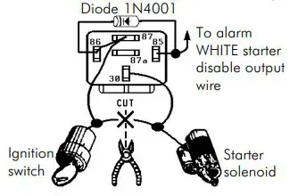
WHITE WIRE (to starter disable), figs. 3a, 3b, 3c
Connect to an optional 30A relay to prevent the car from starting when the alarm is armed.
- A. Locate the starter solenoid wire (carries power from the ignition switch to the starter solenoid). This wire must show +12VDC only when the ignition is in the start position.
- B. Cut the starter solenoid wire.
- C. Test the starter solenoid wire as follows:
- (1) If the wire is cut before the engine is started, the engine should not turn over.
- (2) If the wire is cut while the engine is running, there should be no effect.
- D. Connect the WHITE WIRE and the two halves of the cut starter solenoid wire to the relay as shown in fig. 3a.
- E. If the engine still starts, connect terminal 86 to a wire which shows +12VDC when the engine is both starting and running (fig. 3b).
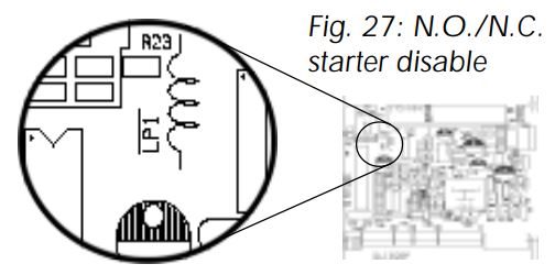
- F. NOTE regarding N.C./N.O. output – The starter disable output is programmable for N.C. or N.O. operation. Default is N.C. (See PROGRAMMING, page 18.) If N.O. starter disable output is required, connect the ignition switch side of the starter solenoid wire to terminal 87 of the starter disable relay instead of 87a, as shown in fig. 3c, then cut the LP1 jumper (see fig. 27 on page 16). All other connections are the same.
Fig. 2 — Connecting to chassis ground

Fig. 3 a — N.C. Starter disable output
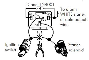
Fig. 3 b — Alternative N.C. starter disable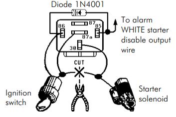
Fig. 3 c — N.O . Starter disable output
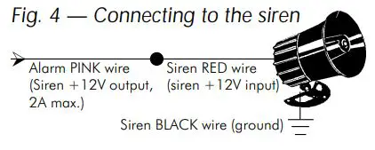
PINK WIRE (to siren), fig. 4
- A. Mount the siren under the hood to the vehicle’s metal body as close to the grill as possible for best sound. The siren must not touch the engine. Mount with the mouth facing down so water will not collect inside.
- B. Connect the siren’s BLACK WIRE directly to the vehicle’s metal chassis. Scrape paint from the metal surface, and use a factory grounding bolt or a star washer.
- C. Connect the alarm’s PINK WIRE directly to the siren’s RED WIRE.
YELLOW WIRE (to ignition switch voltage input)
Connect to a fuse or wire which outputs +12VDC when the ignition key is in the ON and START position, but not the ACC position. This wire must be connected at all times to ensure proper arming and disarming, as well as to operate the VEPL push-button switch.
Connector 3 (6-pin connector)
BLUE WIRE (neg. door trigger input), fig. 5
A. Existing car door switches — Use a VOM meter to locate a wire (usually in the driver’s kick panel) which shows ground when any door is open, and which is not ground when all the doors are closed. Connect to the BLUE WIRE. (NOTE – If this wire shows +12VDC when a door is opened, see PURPLE WIRE below.)
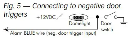
B. If the vehicle (such as a delivery van) has no existing car do o r switches — Mount a pin switch in every do o r yo u wish to protect. Connect each switch to the BLUE WIRE.
PURPLE WIRE (pos. door trigger input), fig. 6

Use a VO M meter to lo cate a wire (usually in the driver’ s kick panel) which shows + 1 2 VDC when any vehicle do o r is o pen, and which is no t + 1 2 VDC when all the doors are closed. Connect to the PURPLE WIRE.
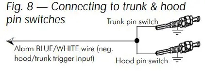
BLUE/WHITE WIRE (negative hood/ trunk trigger input), figs. 7 & 8
A. If the vehicle has a trunk switch, but no ho o d switch Use a VO M meter to lo cate the wire which shows ground when the trunk is o pen, and which is not ground when the trunk is closed. Mount a pin switch in the ho o d. Connect both to the BLUE/ WHITE WIRE as shown in fig. 7 .
 B. If the vehicle has no existing ho o d o r trunk switches Mount a pin switch in both the ho o d and the trunk. Connect both switches to the BLUE/ WHITE WIRE as shown in fig. 8 .
BROWN/WHITE WIRE ( (-) factory honking horn output), fig. 9
Programmable – Supplies a pulsing 2 0 0 mA output to drive a (-) factorial horn relay.
- A. Operation – When the alarm is triggered, this wire pulses 200mA to activate the (-) factory horn honk relay found in most vehicles. This allows the alarm to honk the horns and blast the siren at the same time.
- B. Connection – Connect the BROWN/WHITE WIRE directly to the negative input of the vehicle’s factory horn relay (it should show (–) when the vehicle’s horn button is pressed). Make sure this input draws less than 200mA of current. Otherwise, add a 30A relay to honk the horns.
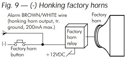
NOTE — If there is no factory horn relay, or if it draws more than 200mA, a separate optional 30A relay must be used with the BROWN/WHITE wire.
BLACK/WHITE WIRE (2nd ch. output), fig. 10
Note — 2 nd channel output works only if the optional ENFO RCER remotes are used.
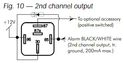
- A. Output — Disarms alarm and supplies a 200mA transistor ground output as long as a valid signal is received if the * transmitter button is pressed for 2 secs. For safety, 2nd channel output operates only:
- (1) If the ignition switch is OFF; or
- (2) If a car door is open while the ignition switch is ON.
- B. Connection — Connect the BLACK/WHITE WIRE to a 30A relay to control trunk release or other accessory. NEVER CONNECT THE BLACK/WHITE WIRE DIRECTLY TO AN OPTIONAL ACCESSORY, AS THIS WILL BURN OUT THE 2ND CHANNEL OUTPUT, AND POSSIBLY THE ENTIRE ALARM BRAIN.
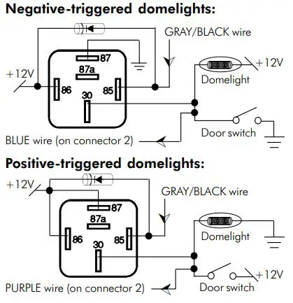
GRAY/BLACK WIRE (dome lights), fig. 11
A. Output — Supplies a 200mA transistor ground output in one of three situations:
(1) When the alarm is disarmed, this wire turns the dome lights on for 30 seconds, or until the ignition key is turned ON.(2) When the alarm is triggered, this wire flashes the dome lights.(3) When the ignition-controlled dome light is enabled, turning OFF the ignition will turn ON the dome light for 30 seconds.
B. Connection — Connect the GRAY/BLACK WIRE via a 30A relay to the domelights. Never connect the gray/black wire directly to the domelights, as this will burn out the domelight output, and possibly the entire alarm brain.
Fig. 11 — Connecting to the do me lights (positive or negative )
Wire connections with factory remotes
Connector 6 (4-pin WHITE connector)
4-Pin Factory Remote Arm/Disarm Interface, figs. 12 to 15
To find the lock switching wire from the interior switch with a VOM meter, lock the driver’s door via the interior central door lock switch. The lock switching wire shows the status changed as long as the interior central door lock switch is pressed.
To find the unlock switching wire from the interior switch with a VOM meter, unlock the driver’s door via the interior central door unlockswitch. The unlock switching wire shows the status changed as long as the interior central door unlock switch is pressed.
The BROWN wire in this connector is the unlock switch defeat input. When connected to the unlock switch lead in the vehicle, the unit will disarm via the keyless entry system only — the switch will have no effect.
NOTE: If the unlock switch defeat is not desired, connect the BROWN input wire to (–) chassis ground prior to teaching the unit the door locks.
To find the passenger door unlock wire from the interior central door lock switch with a VOM meter, unlock all the doors via the OEM remote. The passenger door unlock wire changes status during the unlock operation.
There are four main types of keyless entry systems. Connect the 3-pin white connector’s three wires according to type:
- A For vehicles WITH driver’s door priority unlock and with relays inside the OEM keyless module — This is common with mostFord and some GM vehicles. See fig. 12.
- B. For vehicles WITH driver’s door priority unlock and with relays outside the OEM keyless module — Common with many 4- door GM vehicles. See fig. 13.
- C. For vehicles WITHOUT driver’s door priority unlock and with relays outside the OEM keyless module, and which require thedisarm defeat function — This is common with import vehicles and many Jeep vehicles. See fig. 14
- D. For vehicles WITHOUT driver’s door priority unlock and with relays outside the OEM keyless module, but which do not require the disarm defeat function — This is common with import vehicles and with many Jeep vehicles. See fig. 15.
Note: For C and D above, figs. 14 and 15 show how to install the system in a way that prevents disarming the ENFORCER alarm via the interior central door lock switch.
IMPORTANT: Insert a 1N4004 diode as shown in the diagrams. Near the relays is the best location to insert this diode. Failure to insert the diode at the correct point will allow the ENFORCER alarm to be disarmed by one of the power door lock switches inside the car. If the relays are difficult to locate, call SECO-LARM technical support.
Table A:
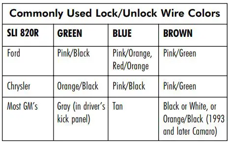
Fig. 12 — Factory arm/disarm for vehiclesWITH driver’s door priority unlock and internal lock/unlock relays.
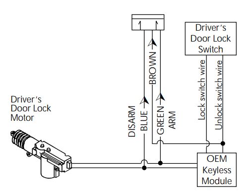
Fig.13 — Factory arm/disarm input for vehiclesWITH driver’s door priority unlock and external lock/unlock relays.

Fig. 14 Factory arm/disarm input for vehiclesWITHOUT driver’s priority door unlock and external relays, but with disarm defeat.
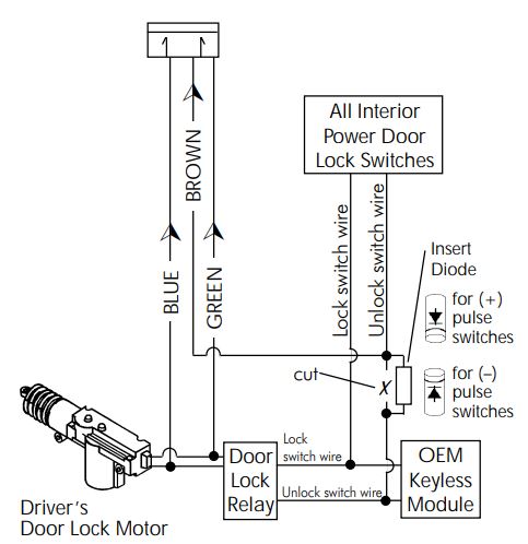
Fig. 15 Factory arm/disarm input for vehiclesWITHOUT driver’s priority door unlock and external relays, but without disarm defeat.

Wire connections Using ENFORCER remotes
Connector 4 (3-pin connector)
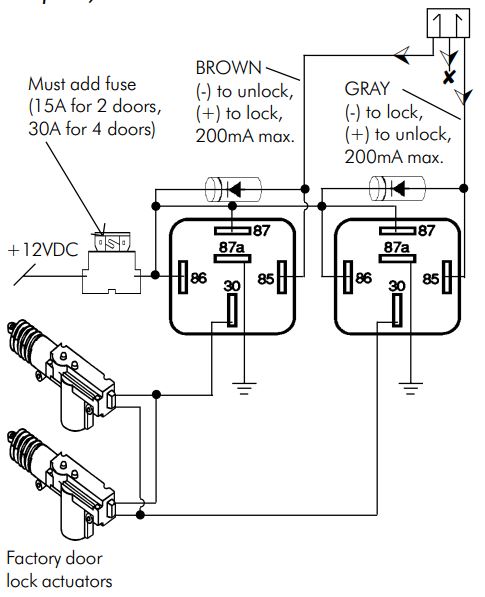
GRAY WIRE (ground output to lock, +12VDC output to unlock)RED WIRE (+12VDC output)BROWN WIRE (ground output to unlock, +12VDC output to lock)Figs. 16 to 22
These 3 wires allow the alarm to control the power door lock/unlock systems of most vehicles without external relays. However, one or two relays may be required in some cases.
The alarm has a built-in timer which is pre-set for 0.5 seconds, but which can be programmed for 3.5 seconds. See PROGRAMMING, page 18.
Types of door lock/unlock systems — At the time this manual was completed, there were seven common types of power door lock/unlock systems in use:
- A. Negative relay switching to factory actuators— The factory door lock switch has 3 wires. One wire always shows ground. The LOCK WIRE becomes ground when the door is locked, and sends a pulse to a factory relay to lock the doors. The UNLOCK WIRE becomes ground when the door is unlocked, and sends a pulse to a factory relay to unlock the doors. Most Japanese cars use this system. THIS IS THE MOST COMMON TYPE OF POWER DOOR LOCK SYSTEM. See fig. 16.
- B. Positive relay switching to factory actuators— The factory door lock switch has 3 wires. One wire always shows +12VDC. The LOCK WIRE becomes +12VDC when the door is locked, and sends a pulse to a factory relay to lock the doors. The UNLOCK WIRE becomes +12VDC when the door is unlocked, and sends a pulse to a factory relay to unlock the doors. Most General Motors cars use this system. See fig. 17.
Fig. 16 (power door lock/unlock outputs) — Negative relay switching to factory actuators
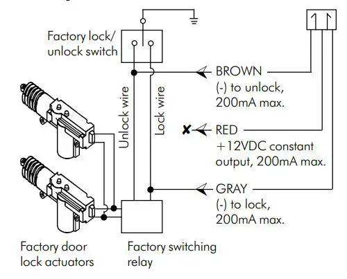
Fig. 17 (power door lock/unlock outputs) — Positive relay switching to factory actuators Factory lock/ unlock switch
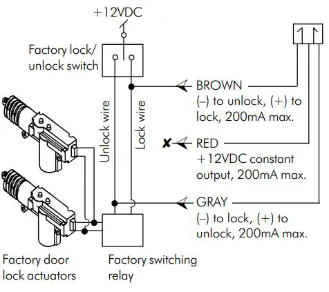
Fig. 18 (power door lock/unlock outputs) — Positive reversal switching to factory actuators
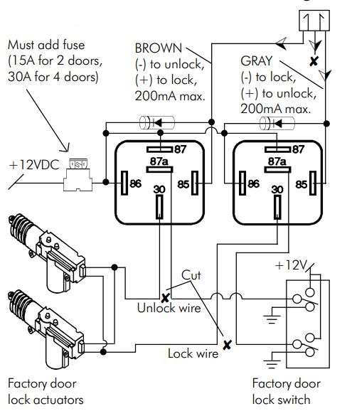
Fig. 19 (power door lock/unlock outputs) — Single wire, polarity switching
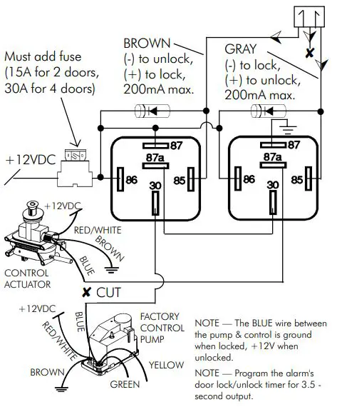
Fig. 20 (power door lock/unlock outputs) — Single wire, positive shunt switching
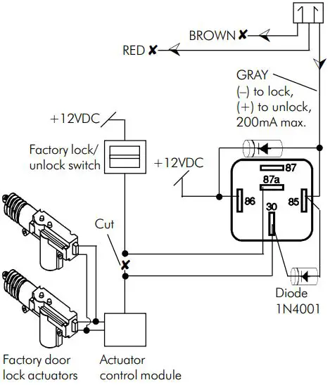
Fig. 21 (power door lock/unlock outputs) — Single wire, negative shunt switching
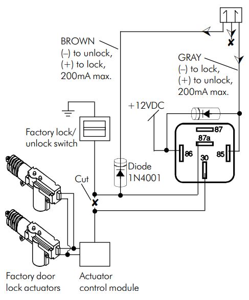
Fig. 22 (power door lock/unlock outputs) — Aftermarket actuators
- C. Positive reversal switching to factory actuators — The factory door lock switch typically has 5 wires. Two wires always show ground, and one always shows +12VDC. The LOCK WIRE shows ground at rest and during unlock, but shows +12VDC when the door is locked. The UNLOCK WIRE shows ground at rest and during lock, but shows +12VDC when the door is unlocked. Many GM trucks, Fords, and Chryslers use this system. See fig. 18.
- D. Single wire, polarity switching — The factory door lock switch uses a single wire to control the door lock and unlock operation. The single LOCK/UNLOCK WIRE shows ground when the doors lock, and +12VDC when they unlock. This is found on most Mercedes Benz and on some other European cars. See fig. 19.
- E. Single wire, positive shunt switching — This system uses a single wire to activate the door locks. Applying +12VDC on the LOCK/ UNLOCK WIRE causes the doors to unlock, and removing the +12VDC (not applying ground) causes the doors to lock. Found on some Ford Probes. See fig. 20.
- F. Single wire, negative shunt switching — This system uses a single wire to activate the door locks. Applying ground on the LOCK/ UNLOCK WIRE causes the doors to unlock, and removing the ground (not applying +12VDC) causes the doors to lock. Found on some Mazda’s and Nissans. See fig. 21.
- G. Aftermarket door lock actuators — If the vehicle does not have power door locks, install aftermarket actuators according to the supplier’s instructions. (If the vehicle has power door locks on all doors except the driver’s door, install one aftermarket actuator on the driver’s door. Includes some Volvos, SAABs, and assorted Japanese models.) See fig. 22.
Connector 1 (4-pin connector) DUAL-STAGE SHOCK SENSOR
YELLOW WIRE (pre-intrusion alert input)BLACK WIRE (ground output)BLUE WIRE (aux. sensor trigger input)RED WIRE (+12VDC output)Figs. 23 to 25
To install the included patented dual-stage electromagnetic shock sensor:
- A. Cable-tie the sensor securely to at least two points under the dash. Do not screw it to metal. Mount so you can reach the adjustment pods. (NOTE — The shock sensor is omni-directional. It can be mounted at any angle.)
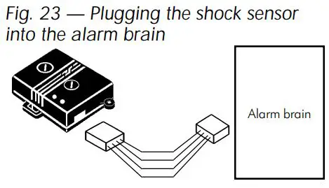
- B. Plug the sensor into the alarm brain’s 4-pin connector.
- C. Set the sensitivity:
- (1) Turn the pre-intrusion (1st stage) sensitivity to maximum (clockwise).
- (2) Test the trigger (2nd stage) sensitivity by rapping hard on the vehicle to simulate an attack. (Do not hit the window.) Adjust the sensitivity by turning the trigger adjustment pod clockwise (more sensitive) or counterclockwise (less sensitive).
- (3) Once trigger sensitivity is set, test preintrusion (1st stage) sensitivity by lightly knocking on the vehicle to simulate someone bumping the car. Adjust the sensitivity by turning the pod clockwise (more sensitive) or counter-clockwise (less sensitive).
- (4) NOTE:
- Changing trigger sensitivity also affects pre-intrusion sensitivity.
- When trigger sensitivity is set to minimum, the shock sensor cannot trigger the alarm (equivalent to turning the shock sensor OFF). Pre-intrusion is also turned OFF.
- When sensitivity is set to maximum, the shock sensor is very sensitive. This may cause unnecessary chirps and/or false alarms.
- To prevent false alarms, the shock sensor and auxiliary sensors will not trigger the alarm until 4 or 60 seconds (depending on the remote used)after the alarm is armed and no further motion is detected ( see sensor delay times on page 19).
NOTE— To connect more than one SECO-LARM dual-stage shock, microwave, or glass break sensor, use an SR-199-315 Y-connector. (See fig. 24.)

NOTE— To install non-SECO-LARM auxiliary sensors — Splice into the shock sensor’s wire harness as shown in fig. 25. For single-stage auxiliary sensors, do not use the YELLOW WIRE.
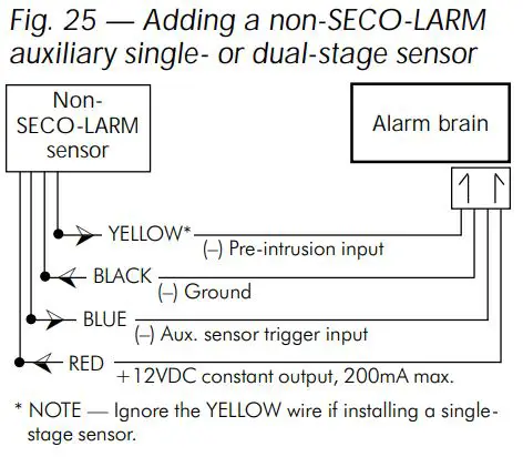
IMPORTANT— These four wires are transistor +12VDC or transistor ground inputs and outputs with max. ratings of 200mA. Take care when connecting accessories to these wires.
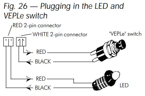
Connector 7 (2-pin RED connector) PLUG-IN LED, fig. 26
- A. Determine where to mount the LED. The LED should be easily seen by potential thieves and vandals. However, do NOT mount where the LED is easily exposed to sunlight. Discuss the LED location with the customer before starting.
- B. Drill a 1/4″ hole in the LED location.
- C. Run the LED connector through the hole, and then plug into the alarm brain’s 2-pin RED connector.
IMPORTANT – DO NO T CO NNECT THE LED DIRECTLY TO THE CAR’ S BATTERY, O R IT WILL BURN O UT.
- A. Determine where to mount the VEPLe switch. Location is not important for security, as the VEPLe switch cannot be used without the ignition key. It should be hidden from view, yet easily accessible by the user in an emergency. IT IS IMPORTANT THAT THE USER CAN EASILY REMEMBER THE LOCATION OF THE VEPLe SWITCH.
- B. Drill a 9/32″ hole where the VEPLe switch will be mounted.
- C. Run the VEPLe switch connector through the hole, and then plug into the alarm brain’s 2-pin WHITE connector.
Programming & Auxiliary Functions
CURRENT SENSING & SWITCH SENSING
- A. The alarm has a current sensing delay of 60 seconds when a factory remote is used and a current sensing delay of 4 seconds after the alarm arms when the optional ENFORCER remote is used. In other words, current sensing does not trigger the alarm until 4 or 60 secs. after the alarm is armed.
- B. If the alarm is programmed for current sensing, but does not detect the opening of a door, it is possible the domelights do not draw enough current. In this case, try a brighter domelight (check the vehicle manufacturer’s specifications), or connect a non-polarized capacitor (47μF or larger) in parallel across the domelight.
- C. Note regarding current sensing:
- (1) If the domelight burns out or is constantly left ON, the alarm will not detect the doors opening.
- (2) If current sensing and passive arming are desired, connect the door pin switches to the alarm. Otherwise the alarm will not arm properly.
STARTER DISABLE PROGRAMMING (N.O./N.C.)
The starter disable relay can be programmed for N.O. operation. To change it to N.O. operation:
- Take off the bottom of alarm brain unit.
- On the back of the printed circuit board, cut the “LP1” loop as shown on Fig. 27.
- Program via the VEPLe switch as shown on page 18
CODE LEARNING
Note – This section applies only if the optional ENFORCER remotes are used.
The alarm can learn a max. of 4 remotes. RF Code Wash™ deletes all previous remotes when any new remote is learned. This prevents unauthorized use of lost or stolen transmitters, and, because the user’s transmitter no longer works, alerts the user if someone has secretlycode learned a new transmitter. However, it also means that, when code learning is being done, ALL THE USER’S TRANSMITTERS MUST BE CODE LEARNED AT THE SAME TIME.
A. Procedure:
- Disarm the alarm.
- Turn ignition switch ON, then OFF, then ON, then OFF.
- Press the VEPLe button three times within 15 secs. of turning the ignition OFF. The siren chirps once.
- Within 15 seconds, push any button of the first transmitter to be learned. At this time, all previous codes are deleted, and the alarm learns this transmitter’s code. 1 chirp confirms code is learned. (If no button is pressed within this 15-second period, code learning is exited, and old codes are retained.)
- Within 15 seconds, push any button of the second transmitter to be learned (if applicable). 1 chirp confirms learned.
- Repeat step (5) until all transmitters are learned. The siren chirps once for each transmitter when its code is successfully learned.
B. Exit the code learning procedure — The alarm chirps the siren two times, exits the code learning mode, and is disarmed after learning the fourth transmitter’s code, or if you turn the ignition switch ON, or if you do nothing for 15 seconds.
The VEPLe button is a 4-function push-button switch. It is used for entering and exiting the valet mode, emergency disarm, programming, and code learning.
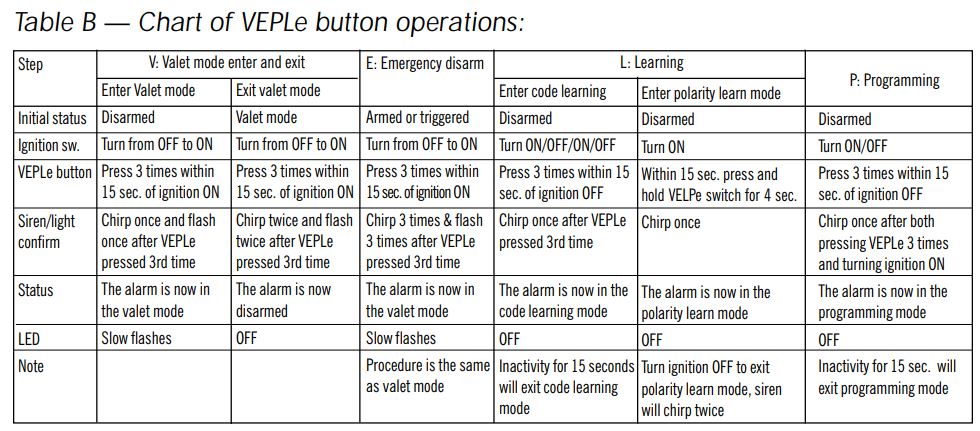
PROGRAMMING
A. Procedure:
- Disarm the alarm.
- Turn the ignition switch ON then OFF.
- Within 15 seconds, press and release the VEPLe button three times and turn the ignition ON again. The siren chirps once. (NOTE — The time from the ignition switch OFF to the ignition switch ON again should not exceed 15 sec.)
- Choose the feature to program — Within 15 seconds, press and release the VEPLe button the number of times needed to select the feature to be programmed. The siren chirps once each time the button is pressed and released. (NOTE — If the VEPLe button is not pressed within 15 seconds, the alarm exits the programming mode.)
- Toggle the feature ON/OFF — Within 15 seconds, press and hold the VEPLe button to turn the feature ON or OFF. The siren continually alternates between 1 and 2 chirps to confirm whether the feature is ON or OFF. Release the VEPLe button after you hear 1 chirp (feature ON) or 2 chirps (feature OFF). (NOTE — If the button is not pressed within 15 secs., the alarm exits programming mode.)
- To program other features, press and release the VEPLe button the number of times to reach the next feature. For instance, if you just programmed feature no. 2, and now want to program feature no. 4, press and release the VEPLe button 2 more times. Then press and hold the VEPLe button to turn the feature ON or OFF as per step (5). (NOTE — You must press the VEPLe button within 15 seconds of the last press of the button.)Notes:
- Does not affect programming chirps or learning chirps.
- For BROWN/WHITE wire only.
- If Off, alarm chirps once when armed manually, whether door is open or closed. If On, alarm chirps 3 times to show if a door is open when armed manually, but also if delayed domelight is On.
- Lock output becomes 25 sec., but unlock support doesn’t change. For specific autos like late-model VWs.
- If N.O. starter disable is selected, loop LP1 must be cut. See page 16.
- Exit programming mode — Three ways:
- a. No VEPLe button activity for 15 seconds; or
- b. Turn the ignition switch OFF; or
- c. Press and release the VEPLe button to choose the 15th feature.
 Notes:
B. NOTE:
- When the programming mode is exited, the siren chirps twice.
- Programming chirps are not deleted with one-time or permanent chirp delete.
DOOR LOCK/UNLOCK POLARITY LEARN MODE
When the adapter is powered up for the first time and if the adapter will be working with the factory remote, then it is necessary to manually teach the adapter the correct door lock/unlock polarity as follows:
- Disarm the alarm
- For a successful learning, It is important to manually lock the door lock switch on the door panel.
- Turn the ignition switch ON.
- Within 15 seconds, turn the VEPLe switch on for 4 seconds. The siren will chirp once to confirm the alarm has entered the polarity learn mode. Then the alarm will automatically learn the arm input, disarm input and disarm defeat input.
- Turn the ignition switch OFF and siren will chirp twice to indicate a successful learning.
TIPS FOR TESTING THE ALARM
- A. Door Lock – Test the door lock by pressing the lock and unlock buttons. If the door lock does not respond, shut down then reconnect the alarm unit’s power, or manually perform the door lock/unlock priority learn operation (see above).
- B. Testing wire connections – Often, when trying to trace a problem between a trigger input, wiring, and the alarm brain, one place to test is at the alarm brain itself. Set the VOM for (+) or (-), depending on the trigger, then probe the appropriate wire near the alarm brain while testing the trigger. For instance, to determine why a (-) door trigger is not working, probe and test the BLUE WIRE of the 6-pin connector near that connector. If the BLUE wire shows (-) when the door is opened, then the problem may be caused by the user not arming the alarm correctly, or the alarmbrain may be defective. But if the BLUE wire does not show (-) when the door is opened, the problem may be a loose or defective pin switch or wire connection.
- C. Sensor delay times – The various sensors have a short delay from the time the alarm is armed until the sensor can be triggered. Therefore, after arming the alarm, wait until after the delay period before testing the sensor to be sure that sensor is operatingproperly:(1) Hardwired triggers – 4-second delay.(2) Shock (auxiliary sensors) and Current sensing – 60 second delay for factory remote and 4-second delay for the optional ENFORCER remote.
- D. Triggered zone recall – When the alarm is armed, trigger any one zone of the car. Then disarm the alarm. The number of flashes on the LED will indicates which zone was last triggered, regardless of when it was triggered:(1) 1 flash – The ignition was triggered.(2) 2 flashes – Panic was triggered.(3) 3 flashes – Shock or auxiliary sensor was triggered.(4) 4 flashes – A door was opened.(5) 5 flashes – The hood or trunk was opened.(6) 6 flashes – The current sensor was triggered.
This memory display will stop only after 15 seconds of inactivity.
Troubleshooting Guide

![]()
SECO-LARM’s ENFORCER SLI 820R/-4 is protected by the following patents:U.S. pat. nos. 4543568, 4706064, 4926160, 4975678, 4980666, 5216407, 5298879Taiwan pat. nos. 19593, 26690, 23474, 33201, 33687, 40938, 66042, 75669, 76872, 84396, 94510, 105843, 118811U.K. pat. nos. 2177529, 2179482, 2279792, 2271009German pat. nos. G9212809.2China pat. nos. ZL02305807.2, ZL02305808.0Other international patents are pending.
[xyz-ips snippet=”download-snippet”]