SRP SeriesQuick Start Guide
Welcome to the SRP Series
Smawave SRP series ruggedized outdoor CPE provides LTE service in a ruggedized form factor. With an operating temperature range of -40 ℃ to +70 ℃endurance, they offer industrial-grade environmental qualifications while providing higher speeds data services for video and other bandwidth-intensive applications. SRP series industrial CPE has very strong anti-vibration ability and it is qualified for extreme industrial environments and ideally suited forrail, transportation, mining, oil and gas, manufacturing, and other outdoor applications.With the diverse self-developed LTE-A embedded modules integrated, SRP series industrial CPE can support multi-bands for Private LTE, even support uncommon frequencies. SRP series industrial CPE can provide accurate real-time location information. The built-in GNSS receiver supports GPS, GLONASS, BEIDOU, and Galileo constellations. This document will serve as a quick start guide for SRP series ruggedized outdoor CPE. In this document, the SRP series ruggedized outdoor CPE will be replaced by the CPE.Carefully read the following safety symbols to help you use your CPE safely and correctly.
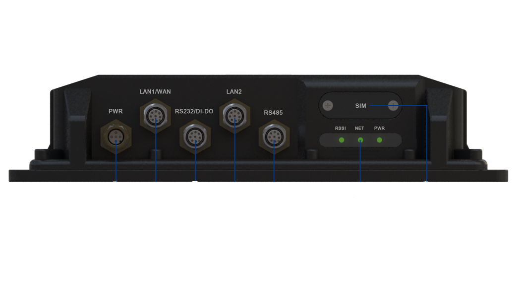
Equipment Appearance
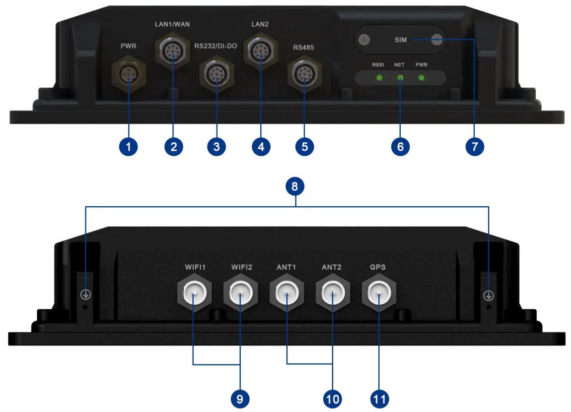
| 1. power port2. LAN2 port3. SIM interface4. LTE antenna interface5. LAN1/WAN port6. RS485 port | 7. Ground screws8. GPS antenna interface9. RS232/DIDO port O10. LED interface11. WIFI antenna interface |
Note1The reset button is beside the SIM interface, if press 1s, CPE will restart; if press above 10s, CPE will factory reset.Note2There are two white ground screws also behind the device.
RS232/485 Cable Definition
|
M12 RS232/485 cable definition |
||||
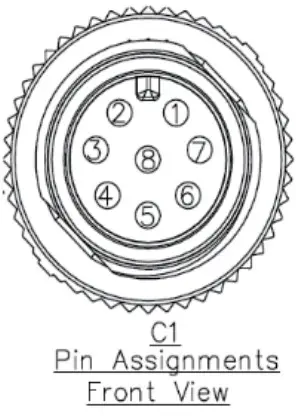 |
Number |
Colors | RS485 |
RS232+DIDO |
| 8 | Brown | RS485_A | RS232_RX | |
| 7 | Brown&white | RS485_B | RS232_TX | |
| 6 | Green | RS_GND | RS_GND | |
| 5 | Blue&white | RS_GND | RS_GND | |
| 4 | Blue | RS_GND | DI1 | |
| 3 | Green&white | RS_GND | DO1 | |
| 2 | Orange | NC | DI2 | |
| 1 | Orange&white | NC | DO2 |
Working Environment
| Operating | -40°C- 70°C |
| Storage | -40°C-80°C |
| Humidity | 5%-95% |
| Power Supply | 9-36VDC |
| Power Consumption | <12W |
| Water and Dustproof | IP67 |
Packing List
|
Items |
Accessories |
Qty |
| 1 | M12 A-Code cable to RJ45 jack ADC2 (Ethernet cable) | |
| 2 | M12 A-Code 8Pin cable ADB1 (Data cable) | 1 |
| 3 | M12 A-Code 4Pin cable M12A (Power cable) | 1 |
| 4 | Mounting bolts (M5’20) | 4 |
| 5 | Grounding cable | 1 |
| 6 | M12 Protective cap | 5 |
| 7 | TNC protective cap | 3/5 |
Configure Hardware
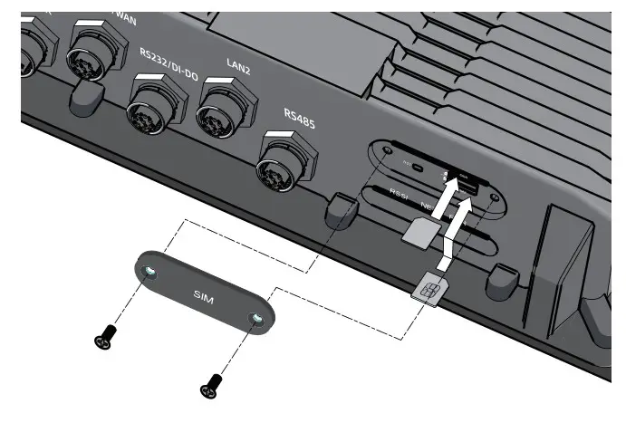
Install SIM CardsStep1Use a cross screwdriver to remove the SIM card cover.Step2Slide the SIM cards into the SIM card slots until they click into place. By default, the SIM card in slot 1 (the upper slot) is the Primary SIM card. When the SRP router is powered on or reboots, it automatically connects to the network associated with the Primary SIM card.Step3Re-attach the cover.
Connect and Turn on the Router
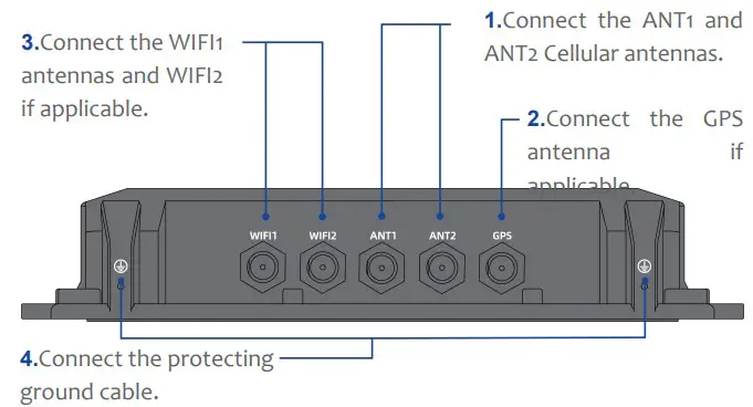 |
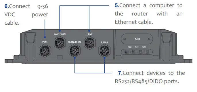 |
Connect to the Network
When the router is powered on, a green PWR LED may occur. This indicates that the power input is good.Once the router’s radio module is configured for the SIMcard, it begins the activation/provisioning process and attempts to connect to the mobile network. This process typically takes several minutes. A successful connection is indicated by a solid green NET LED. And the strength of the RF signal can be indicated by the RSSI LED in different colors.
| PWIR | Green | Power on |
| Off | No power supply | |
| NET | Green | Register to network |
| Off | Not register to the network | |
| RSSI | Green | Signal strong |
| Yellow | Signal good | |
| Red | Signal weak | |
| Off | No signal |
Configure Software
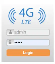
Log in to the Web Management PageStep1Launch the web browser, enter http://192.168.0.1 in the address bar, and press Enter. Step2Enter the user name and password, and click Log In.Step3You can log in to the web management page after the password is verified.
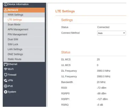
The default user name and password are both admins. If you want to view or configure the CPE more, you should use the super account to log in to the web management page. The default super user name is super admin, and the password is admin.LTE SettingsTo set the LTE network, perform the following steps:Step1Choose Network >LTE Settings;Step2In the Settings area, you can set the configuration of LTE network;Step3In the Status area, you can view the LTE network connect status, such as Frequency, RSSI, RSRP, 0RSRQ, CINR, SINR, Cell ID and so on.
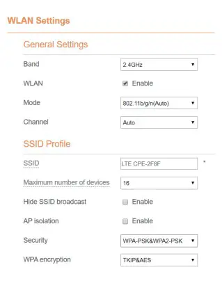
WLAN Settings
Step1Choose Settings → Wi-Fi → WLAN Settings.Step2In the General Settings area, set Wi-Fi Enable or enable Wi-Fi.Step3In the Setting area, change the SSID, such as “LTE-Router”.Step4To ensure data security, it is recommended thatStep5you change the Wi-Fi password.Click Submit to save the settings.
FAQs
The POWER indicator does not turn on.
- Make sure that the power cable is connected properly and the CPE is powered on.
- Make sure that the power adapter is compatible with the CPE.
 report this ad
Fails to log in to the web management page.
- Make sure that the CPE is started.
- Verify that the CPE is correctly connected to the computer through Wi-Fi or a network cable.
- If the problem persists, contact authorized local service suppliers.
The CPE fails to search for the wireless network.
- Check that the power adapter is connected properly.
- Check that the CPE is placed in an open area that is far away from obstructions, such as concrete or woodenwalls.
- Check that the CPE is placed far away from household electrical appliances that generate strong electromagnetic field, such as microwave ovens, refrigerators, and satellite dishes.
- If the problem persists, contact authorized local service suppliers.
The parameters are restored to default values.
- If the CPE powers off unexpectedly while being configured, the parameters may be restored to the default settings.
- After configuring the parameters, download the configuration file to quickly restore the CPE to the desired settings.
The CPE does not support SIM card hot-plug, please confirm that the device has been powered off when the SIM card is inserted or removed.
FCC Regulations:
This device complies with part 15 of the FCC Rules.Operation is subject to the following two conditions: (1)This device may not cause harmful interference, and (2) this device must accept any interference received, including interference that may cause undesiredoperation.This equipment has been tested and found to comply with the limits for a Class B digital device, pursuant to part 15 of the FCC Rules. These limits are designed to provide reasonable protection against harmful interference in a residential installation. This equipment generates, uses, and can radiate radio frequency energy and, if not installed and used in accordance with the instructions, may cause harmful interference to radio communications. However, there is no guarantee that interference will not occur in a particular installation. If this equipment does cause harmful interference to radio or television reception, which can be determined by turning the equipment off and on, the user is encouraged to try to correct the interference by one or more of the following measures:
- Reorient or relocate the receiving antenna.
- Increase the separation between the equipment and receiver.
- Connect the equipment into an outlet on a circuit different from that to which the receiver is connected.
- Consult the dealer or an experienced radio/ TV technician for help.
Changes or modifications not expressly approved by the manufacturer could void the user’s authority to operate the equipment.FCC RF Radiation Exposure StatementThis equipment complies with FCC radiation exposure limits set forth for an uncontrolled environment. To comply with FCC RF exposure compliance requirements, this grant is applicable to only Mobile Configurations. The antennas used for the transmitter must be installed to provide a separationdistance of at least 20cm from all persons and must not be co-located or operating in conjunction with any other antenna or transmitter
[xyz-ips snippet=”download-snippet”]