Smoothtalker D X-TUBE TRUCKER Omni Extreme Performance Antenna Instruction Manual
X-TUBE TRUCKER
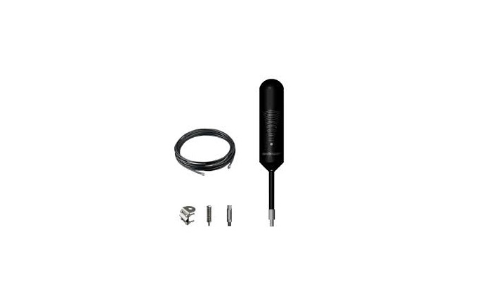
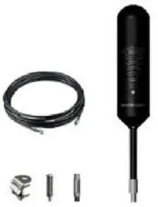
Parts Included
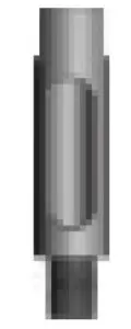
- Mast Extensions

- Side Exit Adapter
- Spring Moun
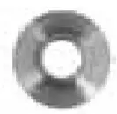
- Washer
- Nut
- Mounting Bracket
- X Kit incl’s1pc 10ft cableXL Kit incl’s1pc 20ft cable
- Antenna Mast


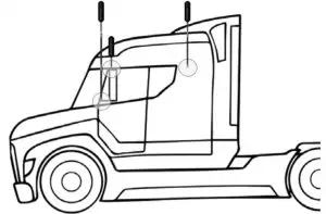
Step 1: Select Mounting Location
Select mounting location on vehicle. The antenna can be mounted in any CB mount or antenna mounting point on the vehicle. For best performance mount the antenna above the metal cab (it does not need to be above the cab wind deflector).
Depending on the type of truck, there may be built-in antenna mounting points. If the vehicle does not have built-in mounting points, the antenna includes a mounting bracket that will work on vehicles with mirror rails. The antenna will also work with third party CB antenna mounts.
NOTE: Mount at least 12 inches from any other antennas. Free of obstructions.
NOTE: Do not use Blue Thread locker on Antenna cable connection points. These are RF connectors and adding Blue Threadlocker will impede performance
Typical Antenna Mounting Points
Max Gain Wide Band Omni Antenna
The Smoothtalker MULTI-BAND X-TUBE TRUCKER Omni Extreme Performance Antenna is specifically designed for Trucks and comes with extra mast lengths for variable height installs to suit multiple truck specific installations. It covers all Cellular Bands 600/700/800/900/1700/1800/1900 /2100/2300/2500/2600 MHz with gains across all bands and transmits and receives across the whole RF Band. It is matched with the latest modulation standards for 3G/4G/LTE/5G spectrum applications. The rugged, ABS UV-resistant housing with ALL stainless and Aluminum hardware withstands harsh outdoor applications and corrosion resistant. High Power handling up to 100Watts without signal degradation.
Electrical Specifications:
|
Frequency range (MHz) |
600-1000/1700-2700 |
|
Polarization |
Horizontal/Vertical |
| Impedance |
50 ohm |
|
VSWR |
≤1.5 |
| Maximum input power(W) |
100 |
|
Lightning protection |
DC Ground |
|
Gain: |
3, 5dBi |
|
Half-power beam width: |
Horizontal :360 Vertical:60 |
|
Connector Type |
MCT Female |
|
Connector position |
Bottom |
|
Size(mm) |
63×240 |
|
Antenna weight(kg) |
0.58 |
|
Wind Cross Section area Ft² |
≤0.2 |
|
Rated wind velocity(km/hr) |
130 |
|
Reflector material |
Aluminum |
|
Material |
ABS UV Stable |
| Color |
Black |
|
Operating temperature |
-40~+55C |
| Mounting hardware |
Alum and Stainless |
|
RoHS Compliant |
2002/95/EC/2003/11/EC |
Assemble The Antenna
Once you have determined the best location for the antenna and have determined if Mast Extensions are needed, insert cable through mast.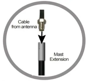
NOTE: Mast Extensions may not be needed depending on your mounting point.
If using Mast Extension(s) add thread locker (packets provided) to thread points(s). Screw into place.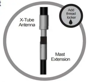
NOTE: Be sure the antenna is the correct height before applying thread locker.
Add thread locker (packets provided) to thread point and screw on the Side Exit Adapter. Do not sure Blue Thread locker on Antenna cable connection points. These are RF connectors and add Blue Threadlocker will impede performance
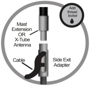 NOTE: If you choose to use this SS cable exit fitting, pls screw it to the mast Rod first before threading the cable through
Antenna Spring (can be used optionlly)
Contact: i[email protected]
References
[xyz-ips snippet=”download-snippet”]