Snap-On Tire Pressure Sensor System Tool Kit TPMS5 User Guide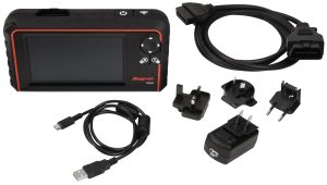
TPMS diagnostic tool to diagnose sensors and relearn TPM systems on Domestic, Asian and European vehicles. Simple icon-based navigation easily navigates from one function to the next. Includes OBD-II connectivity to write sensor IDs to ECU as required. Features vehicle-specific prompts that guide TPM system relearns and software to program aftermarket TPM sensors.
Safety Signal Words
SAVE THESE INSTRUCTIONS
All safety messages contain a safety signal word that indicates the level of the hazard. An icon, when present, gives a graphical description of the hazard. Safety Signal words are:
![]() DANGERIndicates an imminently hazardous situation which, if not avoided, will result in death or serious injury to the operator or to bystanders.
DANGERIndicates an imminently hazardous situation which, if not avoided, will result in death or serious injury to the operator or to bystanders.![]() WARNINGIndicates a potentially hazardous situation which, if not avoided, could result in death or serious injury to the operator or to bystanders.
WARNINGIndicates a potentially hazardous situation which, if not avoided, could result in death or serious injury to the operator or to bystanders.![]() CAUTIONIndicates a potentially hazardous situation which, if not avoided, may result in moderate or minor injury to the operator or to bystanders.Safety Message ConventionsSafety messages are provided to help prevent personal injury and equipment damage. Safety messages communicate the hazard, hazard avoidance and possible consequences using three different type styles:
CAUTIONIndicates a potentially hazardous situation which, if not avoided, may result in moderate or minor injury to the operator or to bystanders.Safety Message ConventionsSafety messages are provided to help prevent personal injury and equipment damage. Safety messages communicate the hazard, hazard avoidance and possible consequences using three different type styles:
- Normal type states the hazard.
Bold type states how to avoid the hazard.Italic type states the possible consequences of not avoiding the hazard.An icon, when present, gives a graphical description of the potential hazard.
Safety Message Example![]() WARNING
WARNING
- Risk of unexpected vehicle movement.Block drive wheels before perofrming a test engine running. Moving vehicles can cause injury.
Safety Precautions
![]() WARNING
WARNING
 Use of diagnostic equipment can cause electrical shock, fire and explosion.Use caution and proper procedures when connecting and disconnecting leads. Diagnostic equipment must be located 18″ or more above floor level. Avoid sparks and other sources of ignition.Electrical shock, flames and explosion can cause serious injury. ·
- Improper use can cause hazardous conditions. Unexpected electrical, thermal or mechanical occurrences can cause injury. Read and follow all safety precautions accompanying the product. Wear safety goggles.
- Electromagnetic and electronically generated waves may interfere with pacemakers.Individuals with pacemakers should never use this product.Using this product with a pacemaker can result in serious injury or death.
- Internal battery presents a risk of fire, explosion and electric shock. Charge battery pack only with charger provided. Do not operate at temperatures above 120°F (50°C). Do not store at temperatures above 140°F (60°C). Do not discard used batteries; return them to a Snap-on repair center for recycling. Follow all safety messages in user manual.Fire or explosion or electric shock can cause injury.
This device complies with Part 15 of the FCC Rules. Operation is subject to the following two conditions:
- This device may not cause harmful interference, and
- This device must accept any interference received, including interference that may cause undesired operation.
![]()
![]()
![]()
![]()
![]()
![]()
For Emergencies only. Call CHEMTREC1-800-424-9300 US and Canada+1-703-741-5970 International3.8 V 4.8 A 18.24 Wh
Input Rating: DC5V, 1AOperating temperature range: -10°C ~ 50°CStorage Temperature range: -20°C ~ 60°COperating Humidity: 20 ~ 85 % RH. NON-CONDENSING Storage Humidity: 5 ~ 95 % RH. NON-CONDENSINGIP54: Dust-Protected and protected against splashing water.
Do not position the equipment so that it is difficult to operate the disconnecting device.
CleaningClean with a soft dry cloth, or if necessary, a soft damp cloth with clean water. Do not use any harsh chemical solvents such as acetone, thinner, brake cleaner, alcohol, etc as this may damage the plastic surface.
The device is restricted to indoor use only when operating in the 5150 to 5350 MHz frequency range.
Federal Communication Commission Interference Statement
This equipment has been tested and found to comply with the limits for a Class B digital device, pursuant to Part 15 of the FCC Rules. These limits are designed to provide reasonable protection against harmful interference in a residential installation. This equipment generates, uses and can radiate radio frequency energy and, if not installed and used in accordance with the instructions, may cause harmful interference to radio communications. However, there is no guarantee that interference will not occur in a particular installation. If this equipment does cause harmful interference to radio or television reception, which can be determined by turning the equipment off and on, the user is encouraged to try to correct the interference by one of the following measures:
- Reorient or relocate the receiving antenna.
- Increase the separation between the equipment and receiver.
- Connect the equipment into an outlet on a circuit different from that to which the receiver is connected.
- Consult the dealer or an experienced radio/TV technician for help.
FCC Caution: To assure continued compliance, any changes or modifications not expressly approved by the party responsible for compliance could void the user’s authority to operate this equipment. (Example – use only shielded interface cables when connecting to computer or peripheral devices).
FCC Radiation Exposure StatementThis equipment complies with FCC RF radiation exposure limits set forth for an uncontrolled environment. The exposure standard for wireless devices employing a unit of measurement is known as the Specific Absorption Rate, or SAR. The SAR limit set by the FCC is 1.6W/kg. The FCC has granted an Equipment Authorization for this device with all reported SAR levels evaluated as in compliance with the FCC RF exposure guidelines. SAR information on this device is on file with the FCC and can be found under the Display Grant section of www.fcc.gov/oet/ea/fccid after searching on FCC ID: 2ANR7-TPMS5 This transmitter must not be co-located or operating in conjunction with any other antenna or transmitter.
Introduction
TPMS diagnostic tool that tests pressure monitoring sensors, captures sensor data, and relearns tire pressure monitoring systems. Also programs aftermarket sensors and various other TPMS functions.
-
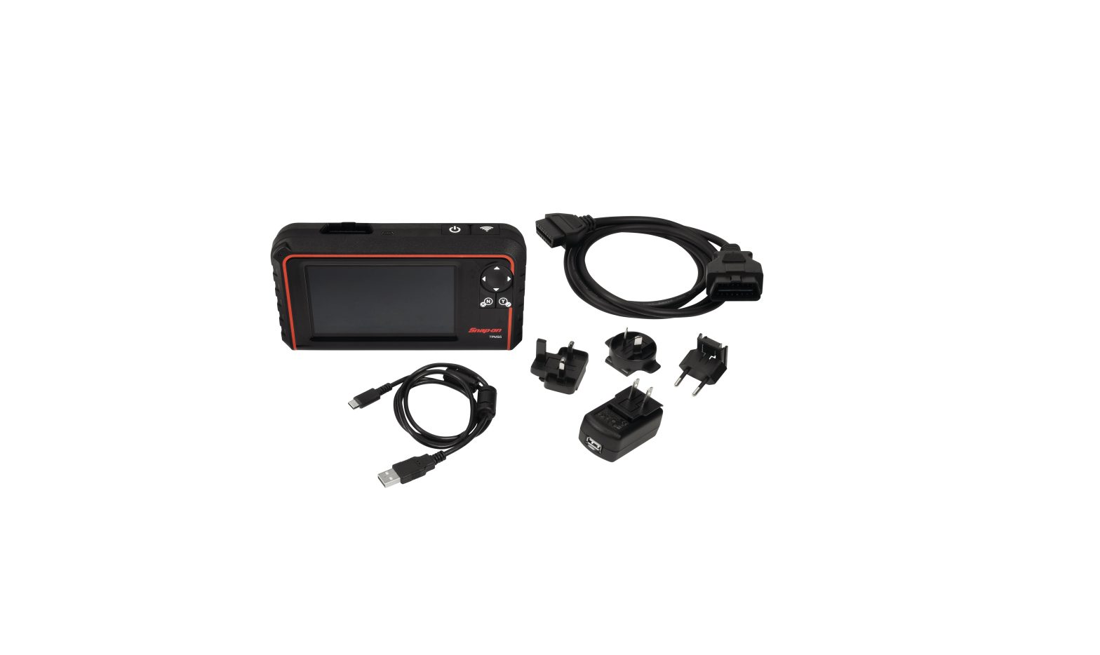
- Kit Contents
- TPMS5TPMS5 Tool Kit
- TPMS5-1OBDII Cable
- TPMS5-4USB Type C Cable
- TPMS5-7AC/DC Power Adapter
- TPMS5-8Lithium Battery
- TPMS5-9Soft Carry Case
- TPMS5-10USB Drive with Manual
- SS203545Quick Start Guide
- Top


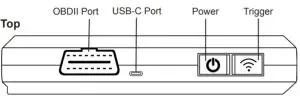
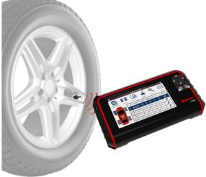
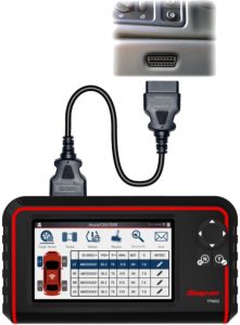
When testing sensors, position the TPMS5 antenna on the sidewall of the tire near the valve. Press the Trigger button to trigger the sensor.For certain applications, the OBDII Cable is needed to perform vehicle relearns, placard adjustments, and more. For these applications, Plug the OBDII cable into the tool, and the other end into the vehicle. The TPMS5 will display OBDII vehicle port locations for easy identification.
A – Main Menu
The Main Menu is a hub to the various features and functions available on the TPMS5. From this screen you will find the main TPMS Function, Special Functions, Update/Registration, Settings, History, and Training.
 report this ad
B – TPMSThe main function of the TPMS5 is to trigger sensors, perform TPMS relearns, replace sensors, and more. This section will cover all the functionalities of “TPMS”.
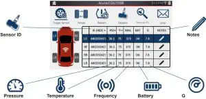
- Trigger SensorTrigger Sensor is selected by default upon entering the TPMS function. From here, using the Trigger button on top of the tool or by tapping the trigger icon on the display (located on the vehicle icon), the tool will trigger TPMS sensors and display all TPMS info.Sensor IDSensor ID is unique to each TPMS sensor and can be displayed in either Hexadecimal or decimal format by tapping the drop down arrow.NotesCustom notes can be entered by tapping the pencil iconPressureTire pressure is displayed in PSI, Bar, or kPa, by tapping the drop down arrow.TemperatureTire temperature is displayed in either Farenheit or Celcius by tapping the drop down arrow.FrequencySensor frequency is displayed. Many Domestic vehicles use 315 MHz, and many Asian and European use 433 MHz.BatterySensor battery status is displayed. If a sensor’s battery is sufficient “OK” will be displayed. If a sensor battery is low, “NOK” will be displayedGSome sensors contain an accelerometer. the G column will display this data if applicable
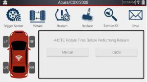
- RotateThe Rotate function is used whenever performing a tire rotation and a TPMS relearn is required. The tool will display specific instructions if a vehicle requires special pressure/tire adjustments before performing a relearn.
- RelearnWhen replacing a sensor, or altering sensor locations, a TPMS relearn is required. The Relearn function displays all necessary steps to put a vehicle into a “learn” mode, to relearn the sensors to the ECU. If applicable, an OBDII relearn can be performed with the OBDII Cable included with the tool. The TPMS5 will display OBDII port locations and instructions.Manual Relearn ExampleOBDII Relearn Example
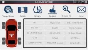
- ReplaceIf a sensor needs replacing, this function can be used to program aftermarket TPMS sensors, view OEM sensor part numbers, as well as images of all sensors. Sensor Programming functions are explained in the next section.Aftermarket ExampleOEM Example
- CreateThe Create function allows the user to program a brand new sensor ID to an aftermarket TPMS sensor.
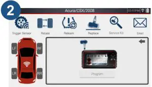
- Select the sensor brand you are working with, then select “Create”.
- Place the sensor above the tool’s antenna, and tap program, or use the Trigger button on top of the tool.
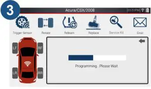
- The tool will begin programming the sensor. This process may take a few moments.
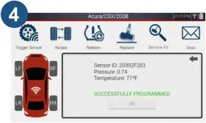
- Once successfully programmed, the tool will display the sensor’s ID, pressure, and temperature.
- Select the sensor brand you are working with, then select “Create”.
 Sensor IDSensor ID is unique to each TPMS sensor and can be displayed in either Hexadecimal or decimal format by tapping the drop down arrow.NotesCustom notes can be entered by tapping the pencil iconPressureTire pressure is displayed in PSI, Bar, or kPa, by tapping the drop down arrow.TemperatureTire temperature is displayed in either Farenheit or Celcius by tapping the drop down arrow.FrequencySensor frequency is displayed. Many Domestic vehicles use 315 MHz, and many Asian and European use 433 MHz.BatterySensor battery status is displayed. If a sensor’s battery is sufficient “OK” will be displayed. If a sensor battery is low, “NOK” will be displayedGSome sensors contain an accelerometer. the G column will display this data if applicable
 Manual Relearn Example
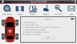 OBDII Relearn Example
 Aftermarket Example
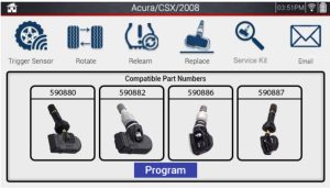 OEM Example
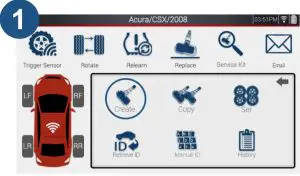
References
[xyz-ips snippet=”download-snippet”]