
SolidRF I RV Travel Cell Phone Signal Booster
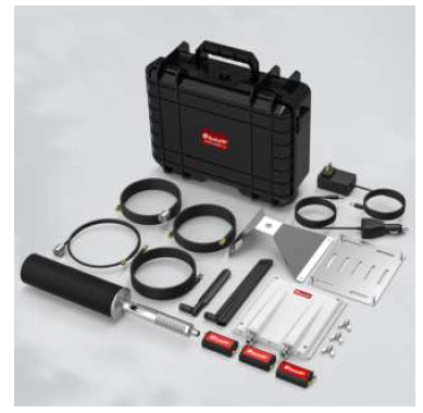
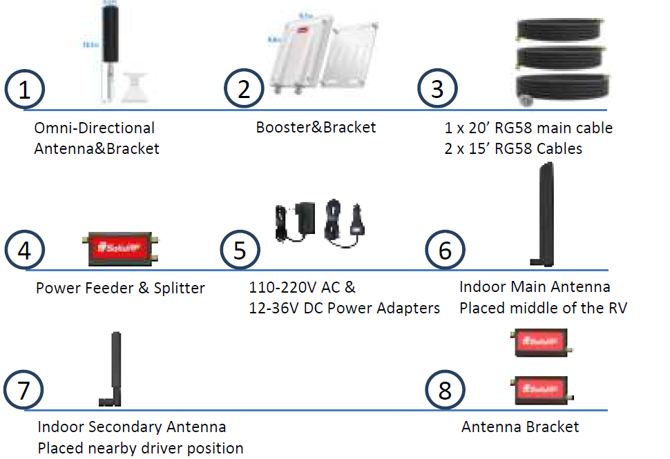
Package Contents
Working Diagram (How It Works)

- The outdoor antenna catches the signal from the nearest cellular tower. Then sends the weak signal to the booster through a 16″ coax cable.
- The booster amplifies the signal, then sends the amplified signal to the “Power Feeder & Splitter” through a 20″ coax cable. The “splitter” divide the signal to “Main Antenna” and “Secondary Antenna”.
- The “Main Antenna” and “Secondary Antenna” rebroadcasts the boosted signal throughout the RV to all mobile devices within range.
- The system also works in reverse; amplifying outgoing signal back to the tower.
Relationship of Distance from Tower and Signal Strength

Coverage Area Ability
Note: FCC regulations limit the amplification of all cell phone boosters in order to prevent damage to the telecommunications infrastructure. Therefore, the maximum coverage area of a booster depends on the original power level of the signal captured by the outdoor unit.
Notice: Boosters will operate poorly when the outdoor signal strength is less than -110dbm (for 3G/1x) or -120dBm (for 4G/LTE). The resulting coverage around the inside antenna will be prohibitively small.
| Power Level
at the Outdoor Antenna Location |
Main Antenna Coverage Area (radius around antenna) | Secondary Antenna Coverage Area (radius around antenna) |
| Strong (5 bars on the cellphone) | 20 ft | 10 ft |
| Medium (3~4 bars on the cellphone) | 10 ft | 5 ft |
| Weak (1~2 bars on the cellphone) | 6 ft | 3 ft |
Installation Guide

Step 1: Study Your RV and Make an Installation Plan
Where do you most frequently use your devices? Choose a convenient location near the center of where you primarily want boosted signal. Keep in mind, you will need a power source near the “Power Feeder & Splitter”. The “Main Antenna” needs to be DIRECTLY below the outside antenna, with a margin of error of 1.5 ft in any direction at floor level. The higher the position of the “Main Antenna”, the smaller the margin of error becomes. We recommend having a vertical separation of at least 4 ft.The “Secondary Antenna” needs to be at least 12 ft away from the outside antenna, but the greater the distance the better.

Once you have decided where you will locate the inside antennas, it’s time to move to the roof. Based on the location you chose for the inside antennas, you should have a pretty good idea of where you need to mount the outside antenna and amplifier– directly above the location of the main inside antenna. Make sure that there is room available in that location. You will need a flat surface large enough to place the mounting bracket. There should not be any electronic equipment or large metal objects within 1 ft of the outside antenna. Furthermore, you will need to route a cable into the vehicle from this location. Consider what entry points are available (refer to Step 3 for further information). You may need to adjust the location of the inside antennas if the resulting position of the outside antenna does not meet these requirements.
Step 2: Outdoor Antenna and Booster Installation
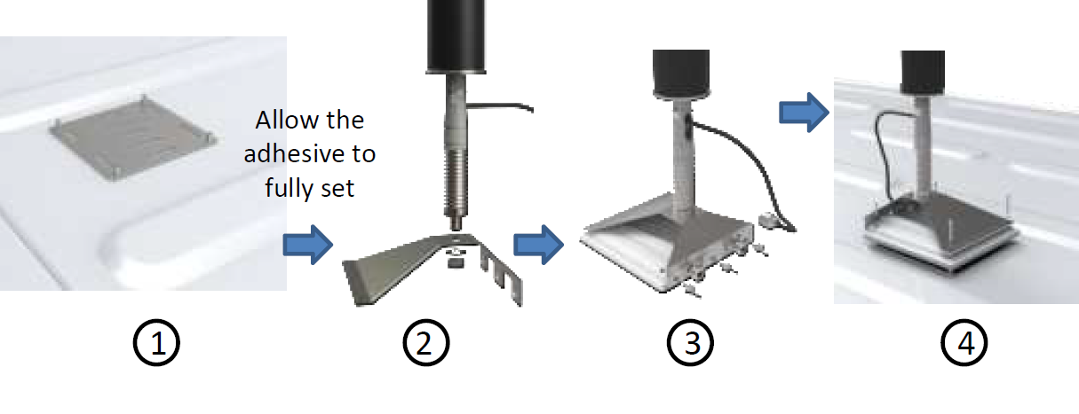
You should always do a “soft install” to test the performance of the booster in the position you have chosen. For now, just securely place the outside antenna and booster in position on the roof then continue to step three. Once you have finalized and tested the installation, use the directions below to mount the bracket using adhesive.
- Using a detergent or alcohol, thoroughly clean the adhesive surface of the mounting bracket and the corresponding location on the roof of the RV. Ensure there is no grease or dirt. This is an important step in achieving the maximum bond strength between the mount and the roof.
- Apply at lest 30ml of adhesive (purchased separately) to the bottom surfaces of the bracket. Cover the whole surface area. The adhesive should be thicker towards the center; it will move outwards and overflow as downward pressure is applied.
- Align the bottom of the bracket with the desired location on the roof of the RV. Apply light pressure, and then slide the bracket in small circles until there is an even layer of adhesive that completely coats the contact surfaces. Re-align the bracket to the desired location and apply firm pressure for at least ten seconds. There should be overflow around the edges of bracket.
- Allow the adhesive to set and solidify for at least 24 hours. Do not install the antenna/ booster or move the frame of the bracket during this time. After 24 hours the bonding strength will be strong enough to support the antenna/ booster, so you may continue with the installation of the booster. Under conditions of 77F and 60% humidity, it will take 3-5 days for the adhesive to fully dry. At colder temperatures, it will take longer for the adhesive to fully dry. Refer to the information on the label of the adhesive.
- The adhesive should be waterproof, UV-resistant, hot and cold weather tested, and resistant to aging. We recommend Fuze*It Liquid Nails, Gorilla Heavy Duty Construction Adhesive, or a similar product from your local hardware store.
NOTE: Make sure to stay below the max height limit allowed by law, which varies from state to state (generally 14’ in western states and 13’6” in eastern states).
Step3: Cable Routing & Inside Main Antenna Mount
Determine where you want the cable to enter the RV, see the suggested options below. Before making any permanent changes, continue with a “soft install” by running the cable through an opened door or window. Use the extension cables as needed. Finalize the routing after testing the performance of the system.
Option A: Use an existing cable entry point, such as access points of: TV antenna, back-up camera, refrigerator or AC vent, etc. (may require you to open and reseal)Option B: Route the cable through a door, going under the weather stripping.Option C: Go through the slide on your RV, using the slider gasket as a seal. Make sure the cable will not be crushed when retracting the slides.Option D: DIY. Find an access point unique to your RV. YouTube is a great source for inspiration.Option E: Create an access point by drilling a hole. Make sure the location of the hole does not void any warranties that came with your RV, and seal up the hole after installation to prevent water leakages.Next, run the cable to the main inside antenna. You can hide the main inside antenna in a cabinet or drawer, however it needs to remain vertical and should not be blocked by large metallic objections like pots and pans.
Note: The location of the antennas will greatly affect the performance of the booster. The main inside antenna needs to be directly below the outside antenna with a vertical separation of at least 4 ft. The horizontal separation between the outside antenna and the secondary inside antenna needs to be at least 12 ft.
Why? All signal boosters are required by the FCC to have built-in protections against self-oscillation. Imagine putting a microphone right in front of a speaker. The feedback makes a horrible screeching sound. The same problem happens when the outside and inside antennas are too close together. The amplifier will automatically reduce the gain of the system until this feedback is gone (the screeching stops) or alternatively shut down the booster completely if oscillation can not be avoided by reducing power.
Step4: Connect the System
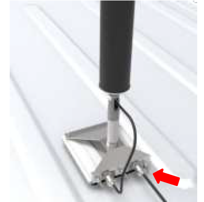
Connect the outside antenna cable to the booster
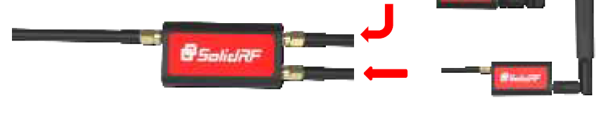
- Connect the outside antenna to the “ANT 2” port on the back of the amplifier. Make sure the connector is properly aligned with the “ANT2” port on the left-hand side of the amplifier (if you are facing the side with two ports), then screw-in the connection. Make sure the connection is secure.
- Connect the amplifier to the longer coax cable Make sure the connector is properly aligned with the “ANT1” port on the right-hand side port of the amplifier (if you are facing the side with the two ports), then screw-in the connection. Make sure the connection is secure.
- Connect the inside antenna to the “Antenna Bracket”
- Connect the 15′ cable to “Antenna Bracket” at the “INPUT” port.
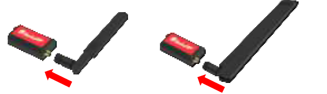
- There are 2 powerful magnets at the bottom of the DC Power Feeder, which can attract the device to the surface of ferrous materials.
- Use the Iron Stiker sttract the “Main Antenna” bracket to non-metallic furniture surfaces in the RV, such as on the inside door of a wardrobe, under a sofa, under a table somewhere
- There are air outlet clips in our accessories, which can attract the “Secondary Antenna” to the air outlet. Or use the Iron Stiker sttract the feeder to car center console or center armrest somewhere, take care not to affect driving operation.Note: Make sure that the indoor antenna is parallel to the horizontal plane
- Connect Booster and Inside Antennas to “Power Feeder & Splitter”. Connect the cable from the booster to port “INPUT” and two cables from inside antennas to the “Main Secondary”, then plug it in to the nearest power outlet.

Trouble Shooting: No Signal Improvement
Step 1: Check power. Ensure the indoor unit is plugged in and the LED Power Light is green.
Step 2: If the power LED solid in red color that means the cable is not connected security. Check cable connections. Ensure the outdoor units are securely connected to the coax cable. If the cable from the splitter to the outside unit is connected properly, the LED should be solid Green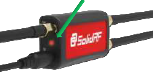
Step 3: Double check the location of outdoor unit and indoor antennas. Make sure that the Minimum Separation Requirements have been met.
Minimum Required Separation Distance Between Booster and Indoor Antennas: Horizontal Distance To Secondary Antenna > 12 feet (4 meters) Vertical Distance To Two Indoor Antennas > 4 feet (1.5 meters) (As far as possible)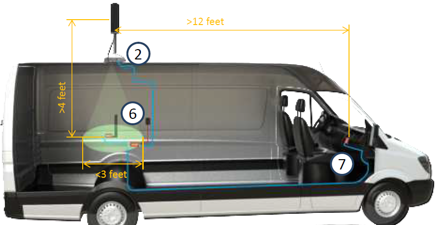
Step 4: Check incoming signal level at outdoor unit position. Usage of a booster is not recommend when the outdoor signal is less than -110dbm(3G/1x) or -120dBm(4G/LTE).
Quick Trouble Shooting
Successful Installation: LED light should be solid green.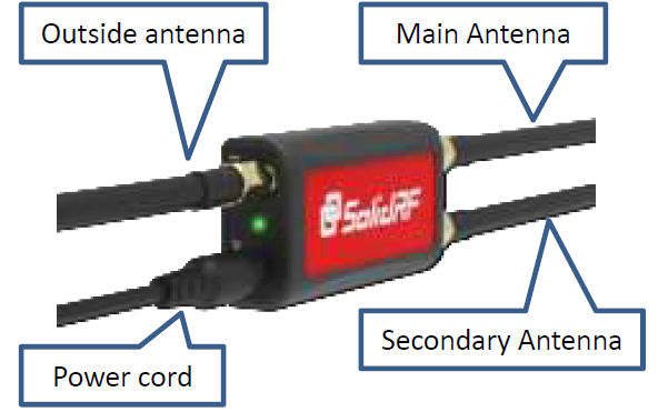
Problem: power light will turn red or off.A red power light indicates a problem with the cable connections. Ensure that all cables are connected to the correct ports (refer to step 3 of installation) and securely connected. If the angle is askew, you may be able to thread the connectors onto the port without creating a successful coupling.
Power Light is off. Please call our technical support number: 877-579-7878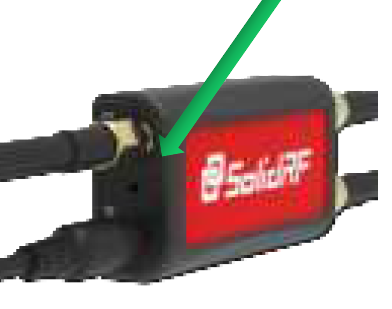
Weather Conditions:The outside antenna and roof-mounted amplifier are waterproof and designed to function in the worst conditions Mother Nature has to offer. However, extreme temperatures may cause problems with performance. Optimal booster performance will occur from -31F (-35C) to 158F (70C). If you are brave enough to go RVing when the outside temperature is beyond this range, the booster will automatically reduce output power to avoid damage.
Trouble Shooting: No Signal Improvement
Step 1: Check power. Ensure the power adaptor is plugged in and the LED Power Light is green.Step 2: Check cable connections. Ensure the indoor and outdoor units are securely connected to the coax cable.Step 3: If the LED light is Red, one of the cables is not connected properly. Unplug the booster and check the cable connections. Make sure all cables are connected to the correct ports. Then plug in the power and reassess performance.Step 4: Double check the position of the main inside antenna. The main inside antenna should be directly below the outside antenna with at least 4 ft of vertical separation. Power-up the system without connecting the secondary antenna. If your signal strength improves, the main inside antenna is in the proper position.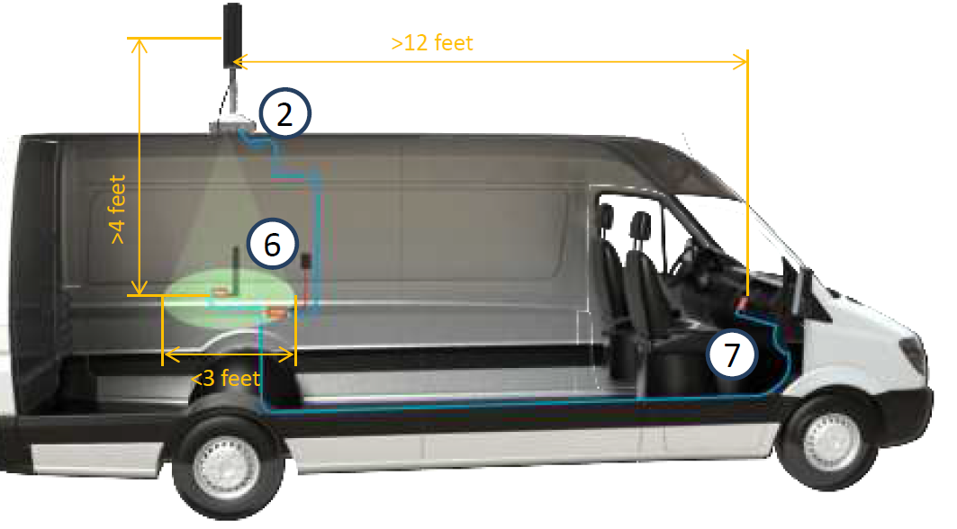 Step 5: Adjust the position of the secondary antenna. Ensure that the secondary inside antenna has at least 12 ft of horizontal separation from the outside antenna. The greater the separation the better.
 Step 6: Check signal strength outside your RV. Signal boosters cannot create a usable signal if there is no signal available to boost. If the signal is less than -110dbm (for 3G/1x) or -120dBm ( for 4G/LTE), the incoming signal from the nearest cellular tower is too weak to be effectively boosted.
WARRANTY
The Booster is covered under a three-year product warranty for failures or defects that result from craftsmanship and/or materials. Dated proof of purchase should be retained fr use in warranty cases. Contact the retailer/reseller directly with any warranty issues, or alternatively contact the manufacturer in cases where the reseller is no longer available to handle warranty claims. In cases where the reseller is unavailable, the product may be returned to the manufacturer at the consumer’s expense, with a dated proof of purchase and a return authorization letter which can be attained by contacting SolidRF.
This warranty does not apply to any signal booster components determined by SolidRF to have been subjected to misuse, abuse, neglect, tampering, or mishandling that result in damages to the physical or electronic properties of the product. Refurbished products that have been recertified to conform to product specifications may be used for product replacements.
DISCLAIMER: The information provided by SolidRF is believed to be complete and accurate, to the best of our knowledge. However, no responsibility is assumed by SolidRF for any business or personal losses arising from the use of the information herein contained, or for any infringements of patents or other rights of third parties that may result from its use.
If you have any questions or concerns when installing or operating your cell phone booster, please email us at
 US: [email protected]Canada: [email protected]Or call our customer service numberOffice (435) 319-6858
References
[xyz-ips snippet=”download-snippet”]