Solplanet Single Phase Inverter Solar Installation Guide
Safety Instruction
- The contents of this document will be updated irregularly for product version up- grade or other reasons. Unless otherwise specified,this document only works as guide. All statements, information and suggestions in this document do not constitute any guarantee.
- This product can only be installed, commissioned, operated and maintained by technicians who have carefully read and fully understood the user manual.
- This product must only be connected with PV modules of protection class II( in accordance with IEC 61730, application class A).PV modules with a high capacitance to ground must only be used if their capacity does not exceed 1 F.Do not connect any sources of energyother than PV modules to the product.
- When exposed to sunlight, the PV modules generate dangerous high DC voltage which is present in the DC cable conductors and live components. Touching live DC cable conductors and live components can result in lethal injuries due to electric shock.
- Allcomponents must remain within their permitted operating ranges at all times.
- Theproduct complies with Electromagnetic compatibility 2014/30/EU, Low Voltage Directive 2014/35/EU and Radio Equipment Directive 2014/53/EU.
Mounting Environment
- Ensure that the inverter is installed out of the reach of children.

- To ensure best operating status and prolonged service life, the mounting ambient temperature of the inverter shoul dbe ≤40°C.
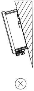
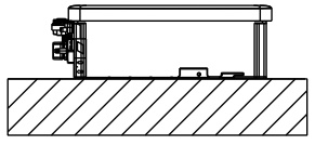
- To avoid direct sunlight, rain, snow, pounding on the inverter, it is suggested to mount the inverter in places with a top protective roof. Do not completely cover the top of the inverter.
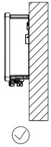
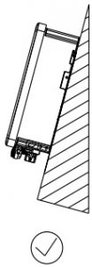
- Themounting condition must be suitable for the weight and size of the inverter. The inverter is suitable to be mounted on solid wall that is vertical or tilted backwards(Max. 15°). It is not recommended to install the inverter on wall made of plaster-boards or similar materials. The inverter may make noise when working.
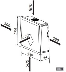
- To ensure adequate heat dissipation, the clearances between the inverter and other objects are recommended as follows:
Scope of delivery
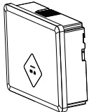
Inverter x1
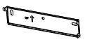
Wall mounting bracket x1
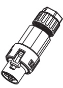
DC connector x2

Communication cover x1 (optional)

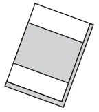
Documentation x1
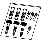
Screw accessory x1
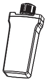
GPRS/WiFi stick x1 (optional)
AC connector x1
Smart meter terminal x1
Magnetic ring x1 (optional)
Inverter’smounting
Use a Φ10mm bit to drill 3 holes at a depth of about 70mm according to the location of the wall mounting bracket.
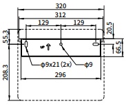 Insert wall plugs into the wall and fix the wall mounting bracket to the wall by screwing three self-tappingscrews(SW10).
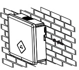
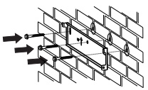 Hang the inverter to the wall mounting bracket.
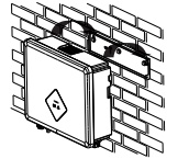 Secure the inverter to the wall mounting bracket using M4 screw.
V.ACconnection
![]() All electrical installations must be done in accordance with all local and national rules.
All electrical installations must be done in accordance with all local and national rules.
- Make sure that all DC switches and AC circuit breakers have been discon-nected before establishing electrical connection. Otherwise, the highvoltage within the inverter may lead to electrical shock.
- In accordance with safety regulations, the inverter need be grounded firmly. When poor groundconnection(PE) occurs, the inverter will report PEgrounding error. Please check and ensure that the inverter is grounded firmly or contact AISWEI service.
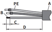
- AC cable requirements are as follows. Insert the conductor into a suitable ferrule acc. to DIN 46228-4 and crimp the contact .
Object
Description
Value
A
External diameter
9-14mm
B
Copper conductor cross-section
2.5-6mm 2
C
Stripping length of the insulated conductors
13mm
D
Stripping length of the cable outer sheath
53mm
The PE conductor must be 2 mm longer than the Land N conductors.
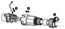
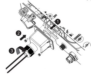
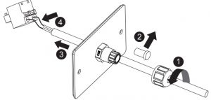
- Loosen the swivel nut of AC connector. Insert the crimped conductors into correspondingterminalsandtighten screws with the accompanied Allen key. Torque: 2.0Nm
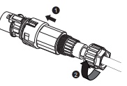
- Insert the adapter to the socket element, stuff the seal ring into the adapter and tighten the swivel nut.
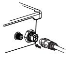
- Plug the AC connector into the socket for the AC connection.
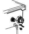
- If required, you can connect a second protective conductor as potentiality bonding.
|
Object |
Explanation |
|
M4×10 screw |
Screwdriver type: PH2,torque: 1.6Nm |
|
OT terminal lug |
Customer provided,type :M4 |
|
Grounding cable |
Copper conductor cross-section: 2.5-6mm 2 |
VI.DC connection
- Make sure PV modules have good insulation against ground.
- On the coldest day based on statistical records, the Max. open-circuit volt- age of the PV modules must not exceed the Max. input voltage of the inverter.
- Check the polarit of DC cables.
- Ensure that DC switch has been disconnected.
- Do not disconnect DC connectors under load.
- Please refer to “DC Connector Installation Guide”.
- Before DC connection, insert the DC plug connectors with sealing plugs into DC input connectors of the inverter toensureprotectiondegree.
VII.Communication setup

- Separate communication cables from power cables and serious interference sources.
- The communication cables must be CAT-5E or higher-level shield cables. Pinassignment complies with EIA/TIA 568B standard. For outdoor use, the communication cables must be UV-resistant. The total length of communicationcable cannot exceed 1000m.
- If only one communication cable is connected, insert a sealing plug into theunused hole of sealingringofthecablegland.
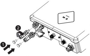
- Beforeconnecting communication cables, ensure the protective film or communication plate attached to the communication opening on the inverter is sealed tightly.
- COM1: RS485(optional)RS485 cable pin assignment as below.
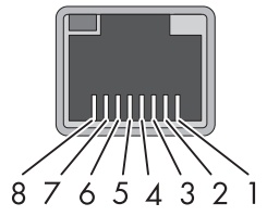
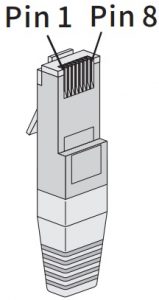 Pin 1=TX_RS485APin 2=TX_RS485BPin 3=NCPin 4=GNDPin 5=GNDPin 6=NCPin 7=+7VPin 8=+7V
2.Loosen the swivel nut of the cable glandon the communication cover, removesealing plugs and lead the cable throughthe swivel nut, sealing ring, communicationcover and magnetic ring.
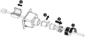
3.Insert the cable into the socket, attach the communication cover to inverter with M4 screws and tighten the swivel nut. Screwdriver type: PH2, torque: 1.6Nm.
COM2:GPRS/WiFi
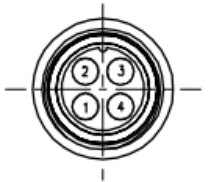
|
PIN |
PIN1 |
PIN2 |
PIN3 |
PIN4 |
|
Assignment |
VCC |
GND |
RS485A |
RS485B |
Theconnectionrefersto“GPRS/WiFi-stickUserManual”
Smart meter
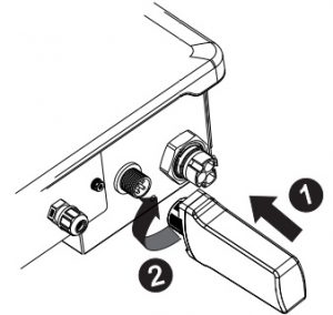
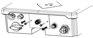
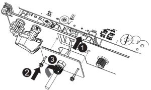
- Remove the communication plate from the inverter.
- Loosen the swivel nut of the cable gland on thecommunication plate, remove the sealing plug and lead the strippedcable through the cable gland and communication plate, press the latch of the smart meter terminaland insert thestripped cable accordingly. Make sure the cableis connected firmly.
- Insert the smart meter terminal to the socket, attach communication plate tithe inverter with M4 screws, and tighten the swivelnut.Screwdrivertype: PH2, torque: 1.6Nm
- If communication cover used, remove only one sealing plug of the cable gland to thread the cable.Detailed installation process follows above steps.
VIII.Commissioning

- Check that the inverter is grounded reliably.
- Check that the ventilationcondition surrounding the inverter is good.
- Check that the grid voltage at the point of connection of the inverter is withinthepermittedrange.
- Check that the sealing plugs in DC connectors and the communication cable glandare sealed tightly.
- Check that grid connection regulations and other parameter settings meetsafety requirements.
- Switch on AC circuit breaker between the inverter and the grid.
- Switch on DC switch.
- When there is sufficient DC power applied and the grid conditions are met, the inverter will start to operate automatically.
IX.EU Declaration of Conformity
Within the scope of the EU directives: – Electromagnetic compatibility 2014/30/EU (L 96/79-106 ,March 29, 2014 (EMC)- Low voltagedirective 2014/35/EU (L 96/357-374 ,March 29, 2014 (LVD)- Radio equipment directive 2014/53/EU (L 153/62-106,May 22, 2014)(RED)AISWEI New Energy Technology Jiangsu Co., Ltd. confirms here with that the
inerternmentionedin this document are in compliance with the fundamental requirements and other relevant provisions of the above mentioned directives. The entire EU Declaration of Conformity can be found at www.aiswei-tech.com.
X.Technical Data
|
Technical Data |
ASW1000S-S |
ASW1500S-S |
ASW2000S-S |
ASW3000S-S |
|
DC Input |
||||
|
Max. PV modules power(STC) |
1500W |
2250W |
3000W |
4500W |
|
Max. DC input voltage |
580V |
|||
|
MPP voltage range |
80-550V |
|||
|
Max. DC input current |
12A |
|||
|
Max. DC input short current |
18A |
|||
|
Max. DC input current, per MPPT |
12A |
|||
| Number of MPPT/strings per MPPT
AC Output |
1/1 |
|||
|
Rated active power |
1000W | 1500W |
2000W |
3000W |
|
Max. apparent power |
1000VA | 1500VA |
2000VA |
3000VA |
|
Rated grid voltage |
220/230V | |||
|
Rated grid frequency |
50/60Hz | |||
|
Max. AC output current |
5A | 7.5A |
10A |
13.6A |
| Adjustable displacement power factor | 0.8 ind 0.8 cap | |||
| Harmonic distortion (THD) at Pac.r
General Data |
< 3% | |||
|
Dimensions (W x H x D) |
320×264×94mm |
|||
| Weight |
6.5kg < 25dB(A)@1m |
|||
|
Noise emission (typical) |
||||
|
DC connection |
Plug-in DC connector |
|||
|
AC connection |
Plug-in AC connector |
|||
|
Communication |
GPRS/WiFi , RS485(Optional) |
|||
|
Display |
LED |
|||
|
Mounting |
Wall mounting |
|||
|
Cooling |
Convection |
|||
|
Operating temperature range |
-25…+60℃ |
|||
|
Relative humidity (non-condensing) |
4000m( 0…100% ) |
|||
|
Max. operating altitude |
Derating above 3000m |
|||
|
Degree of protection |
IP65 |
|||
|
Climate Category |
4K4H |
|||
|
Topology |
Transformerless |
XI.Contact
If you have any technical problems with our products, please contact our service. We require the following information in order to provide you with the necessary assistance:
-Inverterdevice type-InverterserialnumberType and number of connected PV modules-Error code-Mounting location-WarrantycardAISWEI New Energy Technology(Jiangsu)Co., Ltd. Tel.: +865126937 0998Fax: +86 5126937 3159Web: [email protected] tech.comAdd.: Building 9, No. 198 Xiangyang Road, Suzhou, China
AISWEI Pty Ltd.
Tel.: +61 3909 88674 Add.: Level 40, 140 William Street, Melbourne VIC 3000
AISWEI B.V. Add.: Muiderstraat 9/G, 1011 PZ Amsterdam North Holland, Netherlands

http://www.aisweicloud.com/data/download.jsp
References
[xyz-ips snippet=”download-snippet”]