
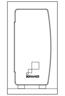
SONANCE SOUNDBARSSB46 M AND SB46 L
INSTALLATION MANUAL
Introduction
Thank you for purchasing the Sonance Soundbar SB46 M or SB46 L. When properly installed your new Soundbar will give you years of entertainment pleasure. The Sonance SB46 M & SB46 L Soundbar is a high performance Left, Center, & Right 3-way speaker system housed in a sealed aircraft grade aluminum enclosure. The SB46 M will align with displays from 50” to 65” diagonal. The SB46 L will align with displays from 70” to 80” diagonal.
Box Contents
Sonance Soundbar Box contains: (1) Soundbar, (2) Flat Soundbar connectors, (2) Display attachment rails, (2) Recessed Soundbar connectors, (1) Key hole wall mount template, (2) Key hole wall mounts, (2) Display spacers and (2) Black opaque strips.
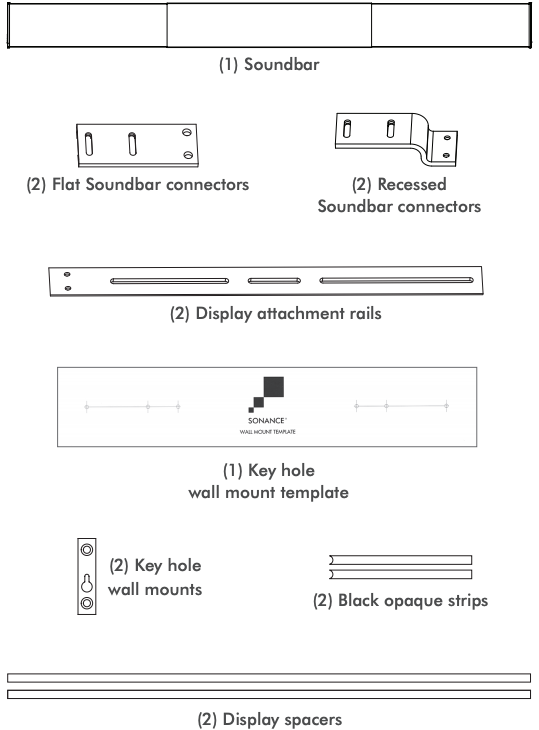
The Hardware Pack contains: A. (4) M8 10mm screws for display attachment rails, B. (4) M8 14mm screws for flat Soundbar connector, C. (4) M8 23mm short screws for recessed Soundbar connector, D. (4) M8 38mm long screws for recessed Soundbar connector, E. (4) M6 25mm screws, F. (4) M8 25mm screws, G. (8) M8 nuts, H. (8) M6 washers, I. (8) M8 washers and J. (4) Rubber feet.

Wall Mount Installations
![]()
Verify the wall mount will support the combined weight of the display and Soundbar.
SB46 M weighs 24 lbs. (10.88 kg) installed. Suitable for displays 50” to 65” (1270mm to 1651mm).
SB46 L weighs 29 lbs. (13.15 kg) installed. Suitable for displays 70” to 80” (1778mm to 2032mm).
NOTE: CAREFULLY FOLLOW INSTALLATION DIRECTIONS FOR THE THIRD PARTY DISPLAY WALL MOUNT.
Before any installation carefully plan where wiring will pass through walls. Perform an obstruction survey using a stud finder to be certain there are no studs, conduit, pipes, heating ducts, pocket doors or air returns in the wall cavity. If you are unsure about obstructions, drill a small hole near where the Soundbar wire terminals will be located and insert a coat hanger wire into the hole to feel around for possible obstructions.
Run three sets of speaker wires: Left channel, Center channel, Right channel as well as the necessary video cable from the amplifier to the display location. Whenever possible leave extra wire to make it easy to connect the wire to the Soundbar spring terminals prior to hanging the display. Extra wire can then be pushed back into the wall.
NOTE: CONSULT LOCAL BUILDING CODES BEFORE RUNNING SPEAKER AND ELECTRICAL WIRES THROUGH WALLS.
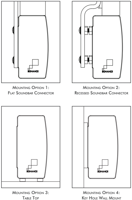
Soundbar Placement and Options Overview
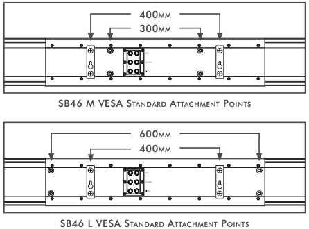
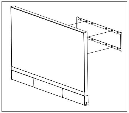
Soundbar SB46 M and SB46 L are designed to attach directly to most flat panel display wall mounts using VESA mounting points with the included attachment rails, connectors, and hardware.
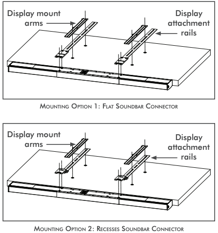
Mounting Option 1 – Flat Soundbar Connector
The Flat Soundbar Connector will align with displays 2 5/8” (65mm) deep.
Mounting Option 2 – Recessed Soundbar Connector
The Recessed Soundbar Connector will align with displays from 1 7/32” – 2 3/32” (31.74mm – 53mm) deep.
Mounting Option 3 – Table Top
Soundbars can additionally be cabinet or table top mounted using the rubber feet included in your box contents.
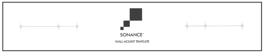
Mounting Option 4 – Key Hole Wall Mount
Key hole wall mounting is an alternative option accomplished by using the key hole wall mounts combined with the wall mount template.
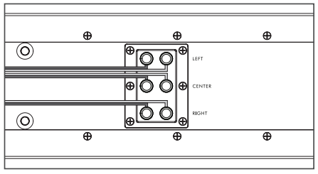
Soundbar Connectors for Wall Mount Brackets
Choose and attach the correct Soundbar connector to the display attachment rails for your desired depth.
The flat Soundbar connector will align with 2 5/8” (65mm) deep displays. The recessed Soundbar connector will align with displays from 1 7/32” – 2 3/32” (31.74mm – 53mm) deep.

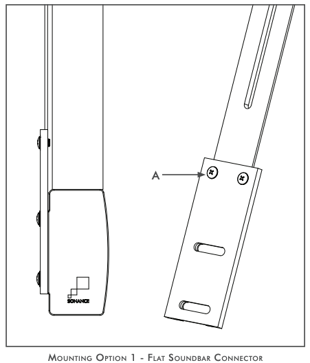
Step 1
Mounting Option 1 – Flat Soundbar Connector
The flat Soundbar connector will align with 2 5/8” (65mm) displays. Use the A screws to connect to the display attachment rails.
Display Spacers
Included with your Soundbar are two 8mm thick wood display spacers. The spacers allow the front surface of the display to be in line with the flat surface on the top edge of the Soundbar.
When using the spacers carefully place the display on top of the spacers. This will require two people. Be careful not to scratch the display. Spacers do not go under the Soundbar.
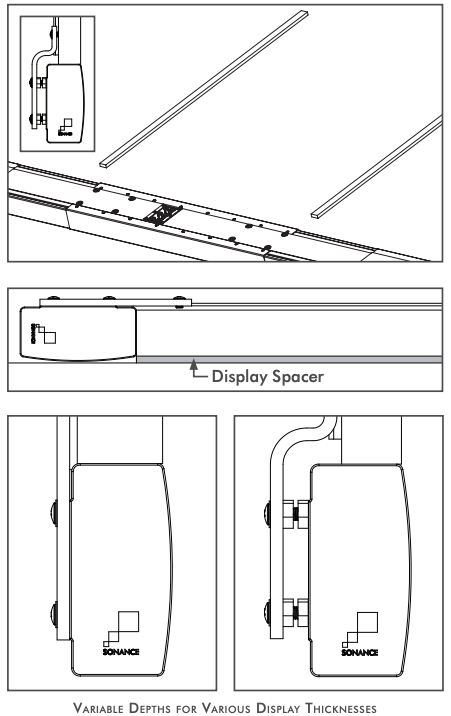
![]() If the spacers are not used the front surface of the display will be in line with the front radius of the Soundbar grille. This is dependent on the display thickness and installation preference.
If the spacers are not used the front surface of the display will be in line with the front radius of the Soundbar grille. This is dependent on the display thickness and installation preference.
Proceed to Step 2
Mounting Option 2 – Recessed Soundbar Connector
The recessed Soundbar connector will align with displays from 1 7/32” (31.74mm) to 2 3/32” (53mm) deep displays.
Various depths can be accomplished by using C or D screws accompanied by I washers and G nuts. Use the A screws to attached the connector to the display attachment rails.
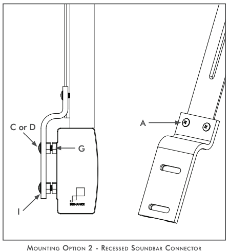

Proceed to Step 2
Step 2
Carefully place the display face down on a soft flat surface. This will require two people. Place the Soundbar face down and position it as close to the display as possible.

Assembly
Position the Soundbar display attachment rails on the back of the display mounting points. Place the display mount arms on top of the display attachment rails. The bottom end of the display attachment rails should be flush with the bottom of your display. Make sure that the screw inserts on the display and attachment rails are aligned.
Position the Soundbar as close to display as possible. Firmly fasten B screws with I washers to connect Soundbar to the Soundbar connectors.

Secure the wall bracket and attachment rails to the display using spacers and screws supplied with the wall mount or E / F screws with H / I washers (depending on the size of the display’s threaded Inserts. E & H are M6 F & I are M8). Hardware will vary. It is recommended to keep spacers and hardware provided with display or display mount. Refer to your display manual for the proper torque to be applied to the screws.

Proceed to Step 3
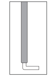
Mounting Option 3 – Key Hole Wall Mount
The SB46 M and SB46 L can be mounted directly to the wall surface.
Choose the Soundbar location and locate the studs with a stud finder. Use a level and the supplied cardboard key hole wall mount template to mark the locations on the wall where the screws should be located. Temporarily tape the template up once it is level and mark the holes with a pencil. Make sure the template is perfectly aligned with the display location then pre drill the pilot-hole locations. The 400mm mounting points corresponds to the spacing of 16” on center studs.
Place Soundbar face down on a soft surface. Attach the two supplied key hole wall mounts to the back of the Soundbar using the supplied A screws. You can use any of the mounting points on the back of the Soundbar.
To hang key hole wall mount use only #10 – #12 pan head or flat head screws (Not supplied). The screws must be firmly attached to the studs to support the weight of the Soundbar. Mate the screw heads into the large round portion of the key hole and gently slide into place.
NOTE: PUTTING SCREWS DIRECTLY INTO THE DRYWALL WILL NOT SUPPORT THE WEIGHT OF THE SOUNDBAR!
If attaching directly to drywall, we recommend self drilling drywall anchors that can easily accommodate the weight of the Soundbars. Also highly recommended are the Toggler® highperformance heavy duty toggle bolts.
Rubber feet can be added to the left and right rear top and bottom edges of the Soundbar to rest against the wall.

NOTE: ADJUST GRILLE AND CONNECT WIRING PRIOR TO HANGING – SEE STEP 3 & 4.

Proceed to Step 6
Mounting Option 4 – Cabinet or Table Top Installation
SB46 M and SB46 L can be mounted in a cabinet or placed on a table top using the included four rubber feet.
Remove the adhesive backing and place the rubber feet on the outer corners on the bottom of the Soundbar.
When using the Soundbar in a cabinet make sure the Soundbar is placed forward near the cabinet front edge, not in the rear of the cabinet. This will ensure best audio quality.
Proceed to Step 3
Step 3
Adjusting Grille Width
Be sure to complete this step prior to attaching the display and Soundbar to wall mount bracket. Adjust the side grilles of the Soundbar to achieve perfect symmetry with the display. Loosen the rear lock screw on each side grille and slide the grille out to match the width of the display. No tool required. Once the width is set tighten the lock screws finger tight.

Included with your Soundbar is a pair of black textured opaque strips. These are used to cover the remaining open area where the lock screw slides through. In some conditions light may pass through this area into the grille. Peel off the adhesive backing and place the strip over the open area and cut to size. The radius side fits against the lock screw.

Proceed to Step 4
Step 4
Soundbar Wiring
We suggest leaving extra wire length to make it easy to connect the wire to the Soundbar spring terminals prior to mounting the display. The extra wire can then be pushed back into the wall.
A. Strip 1/4” – 1/2” (6mm – 12mm) of insulation from each speaker lead. Twist the strands or tin the exposed wire with solder to ensure that there are no stray strands.
NOTE: STRAY STRANDS THAT TOUCH EACH OTHER CAN CAUSE A SHORT-CIRCUIT THAT CAN DAMAGE THE AMPLIFIER.
B. Bend the speaker wires into an L for easy connections to the spring terminals.
C. Soundbar’s six terminals are spring-loaded. Push the top of each terminal down to open the connector and insert the exposed wires into the holes in the spring terminals. The speaker’s positive spring terminals are labeled with a red dot; the negative spring terminals are labeled with a black dot. Double-check that you connected amplifier “+” to speaker “+” and amplifier “–” to speaker “–”on all three channels.
Stereo Wiring
If you are using a 2 channel amp or stereo receiver only hook up the left and right channels of Soundbar.
Connect AC power and video cable to display.
Proceed to Step 5 for mounting options 1 & 2
Proceed to Step 6 for mounting options 3 & 4
Step 5
Mounting the display
Carefully mount the display and Soundbar to wall mount. This will require two people. When lifting be careful not to place too much pressure on, or twist, the Soundbar. This could bend the attachment rails.
NOTE: WHEN LIFTING THE DISPLAY AND SOUNDBAR TOGETHER BE CAREFUL NOT TO PUT TOO MUCH PRESSURE ON THE SOUNDBAR ALONE.
Step 6
Calibration
Soundbar installation is now complete and ready for audio system calibration. Using a subwoofer is recommended. The subwoofer crossover frequency should be set to 100Hz. We recommend the VP10SUB & Amplifier or our Cabinet Subwoofers. The Sonance VP46R SST/SUR, VP66R SST/SUR, and VP66 SST/SUR are perfect surround speakers to mate with the Soundbar.
Use tests tones in the surround processor to verify Left/Center/ Right channels have been properly connected and to set levels.
Your Soundbar will sound great out of the box. However with any high performance loudspeaker a 40 hour play period will “break in” the drivers and enhance the overall listening experience. This only needs to be done once.
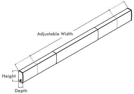
Dimensions
SB46 M
Height: 5 9/32” (134mm)Depth: 2 9/16” (65mm)Adjustable Width: 43 7/8” to 59 5/8” (1114mm to 1514mm)Display Size Range: 50” to 65” diagonal (127cm to 165cm)
SB46 L
Height: 5 9/32” (134mm)Depth: 2 9/16” (65mm)Adjustable Width: 61 1/2” to 77 5/16” (1562mm to 1964mm)Display Size Range: 70” to 80” diagonal (178cm to 203cm)
Sonance Soundbars SB46M AND SB46L Installation Manual – Sonance Soundbars SB46M AND SB46L Installation Manual –
[xyz-ips snippet=”download-snippet”]