
SOUNDSTREAM Car Audio System
Owner's Manual

WARNINGMake sure you choose a suitable place to mount the unit. The position should be completely dry with a good circulation of air, and from a mechanical point of view very stable .
System Planning
Proper system planning is the best way to maximize your amplifier performance. By planning your installation carefully you can avoid situations where the performance of the reliability of your system is compromised. Your authorized dealer has been trained to maximize your system’s sonic potential. Your dealer is a valuable resource in helping you with your system design and installation.
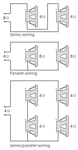
Speaker RequirementsEach channel of your amplifier can easily drive 4Q speaker loads when used in the stereo mode. When a channel-pair is bridged, the recommended minimum load impedance is 3Q for subwoofer use, and 4Q for full range operation. Although operation with lower impedances is not likely to cause immediate damage to the internal circuitry, the unit will most likely overheat, causing the thermal protection circuitry to shut down the amplifier. When the chassis cools down, normal operation will resume. Continuing to operate the amplifier under these conditions is not recommended and will reduce its life expectancy.
Most speakers designed for car audio operation are 4Q impedance. Connecting two such speakers in parallel will result in a 2Q impedance load as seen by the amplifier. Some subwoofer models feature a dual 4Q voice coil design. Connecting these voice coils in parallel will result in a 2Q nominal impedance, which is not recommended for use with bridged channels of your amplifier.
Power Connection Leads
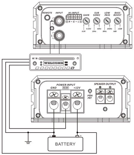
Notes on the power supply
Connect the + 12V power input lead only after all other leads have been connected.
Be sure to connect the ground wire of the unit securely to a metal part of the car.
A lose connection may cause a malfunction of the amplifier.
REMOTE: The unit is turned on by applying + 12Volts to this terminal This terminal dose not draw heavy current like the two power terminal so a thinner connecting wire is acceptable. Standard 18 GAUGE is fine and the standard colour is yellow. If the radio is equipped with a power antenna control wire, it can drive this terminal. If the power antenna wire is already in use, you can still splice into it. With this method, the unit will turn on automatically with the radio. Use the power supply lead with a fuse attached whose value is the same as original fuse.
Place the fuse in the power supply lead as close as possible to the car battery.
During a full power operation, Maximum current will run through the system. Therefore,
Make sure the that the leads to be connected to the + 12v and GND terminals of the unit respectively must be larger than 10-Gauge (AWG.10).
System 1 connection subwoofer
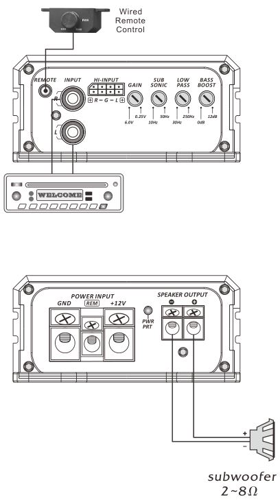
System 2 connection subwoofer

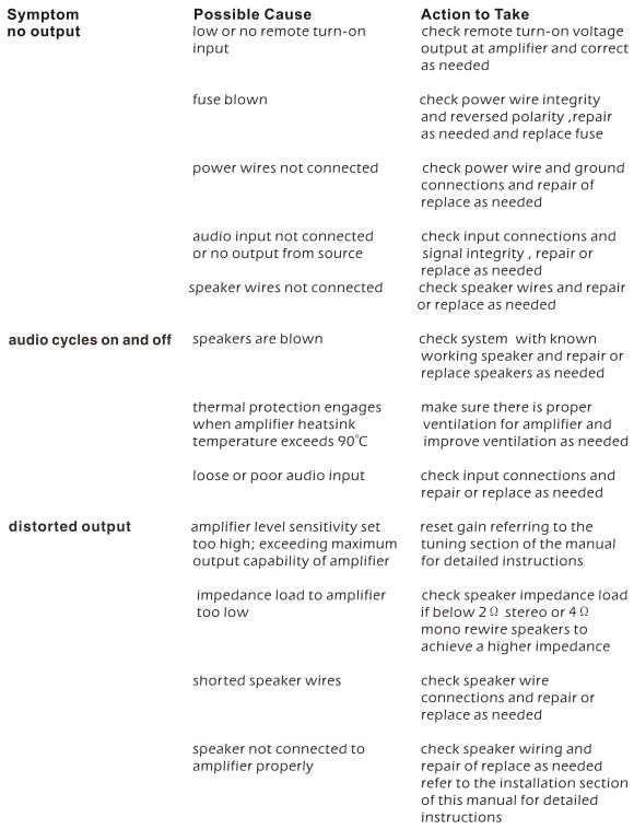
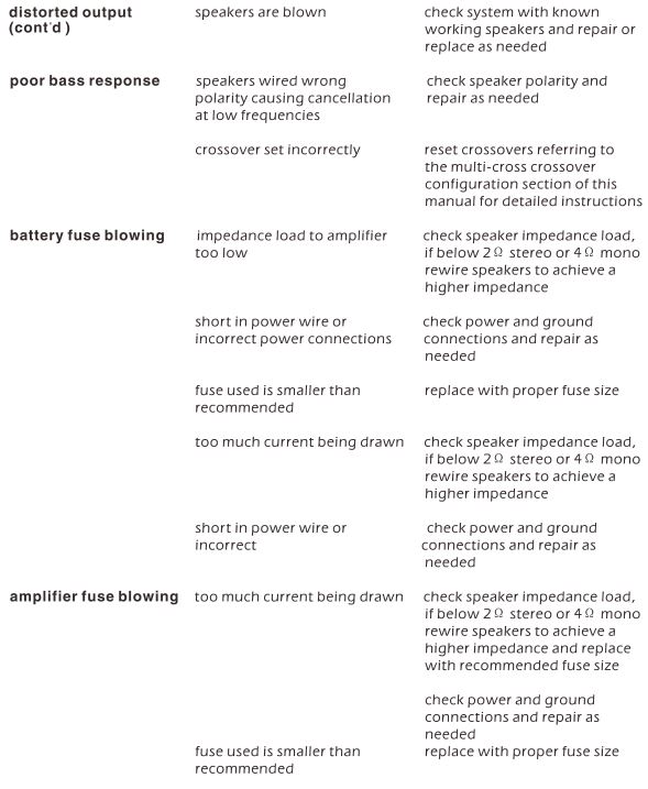
Trouble Shooting
Specifications
RSM1.2000D
Mono Mono Mono2000w MAX PowerVariable 30-250Hz 12dB Low Pass CrossoverVariable 10-50Hz 12dB Subsonic CrossoverVariable 0-12dB 45Hz Bass BoostTotal Harmonic Distortion: 0.5%@4-ohmFrequency Response: 10-250HzSignal-to-noise Ratio: 70dBInput Sensitivity: 250mV-6VDimensions. 3.75″wx1.75″hx7.50″l
RSM1.4000D
Mono Mono Mono4000w MAX PowerVariable 30-250Hz 12dB Low Pass CrossoverVariable 10-50Hz 12dB Subsonic CrossoverVariable 0-12dB 45Hz Bass BoostTotal Harmonic Distortion: 0.5%@4-ohmFrequency Response: 10-250HzSignal-to-noise Ratio: 70dBInput Sensitivity: 250mV-6VDimensions. 3.75″wx1.75″hx9.25″l
[xyz-ips snippet=”download-snippet”]