
SOUNDSTREAM SR4-1300/ SR4-1800 4-Channel Amplifier Owner Manual
PANEL DEFINITION
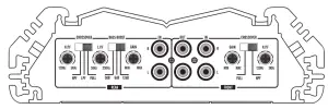
- SR 4-1300

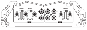
- SR 4-1800

Features & Functions
Position H.P.FHigh pass (frequency response is limited downwards. )
Position L.P.FLow pass (frequency response is limited upwards. )Position FULLProvide a full range signal to the speakers ( whole frequency response).
Input-RCA Input (Rear)Full range line input to connect with the source unit RCA output.H.P.FSet high pass frequency : from 120HZ-3kHZ
Input-RCA Input (Front)Full range line input to connect with the source unit RCA output.Line out-RCA OutputRCA Ouțput to send the line signal to additional amplifiers.
Position H.P.FHigh pass (frequency response is limited downwards. )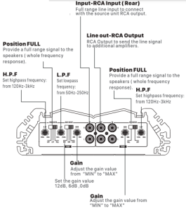
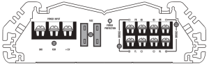
FuseThe integrated amplifier fuses protect the units from short circuit and overload.
Speaker Terminals:T he speaker terminals are Gold Plated for high conductivity and minimum impedance loss. Be sure to strip just enough insulation off your speaker wires that will fit under the screw plate to help ensure against speaker wire short circuits.The unit can support an impedance load as low as 2ohms per channel or 4 ohms in the bridged mode.Bridged mode is designed for 4 -8 ohm loads and will not supports a 2 ohm load.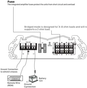
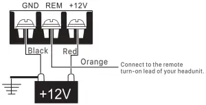
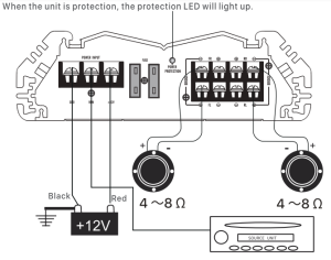
Power Terminals:B+/+12V. Connect the +12V pole of power supply directly to the battery(+) position.GND. Connect the GND pole of power supply directly to the (-) negative ground battery terminal of car chassis.
REM. Connect the “Remote” pole to external switch for positive12V ON/OFF. This may e connected to the power antenna of turnon lead of the headunit.
Power Connection:For your convenience, high current barrier strip terminals are provided which allow the use of heavy gauge terminals and wire without splicing.B+/+12V. Connect the +12V pole of battery.GND. Connect the chassis ground of auto.REM. Connect to the remote turn-on lead of your headunit.Note:Improper wiring connections can seriously damage amplifiers, accessories, or speakers, please follow instructions carefully. Disconnect the battery positive (+) before making any power connections to the amplifier.Make sure all connections are clean and secure, and use gromments when going through the firewall and other metal bodywork. Always use the proper size fusing, with a fuse at the battery and the amplifier.(not supplied)
Input Connection:Connect the pre-amp( low-level) outputs from your source unit or crossover to the RCA jacks labeled ”input” on the amplifier. Be sure to route all signal cable away from power lines and use high quality RCA cables to insure good signal transfer and to avoid noise from entering the system.In the Stereo mode, connect the left and right RCA plugs from the source unit to their appropriate input jacks.In the Mono/Bridged mode, connections may be made to right , left of both input jacks.If you are using a pre-amp device, such as the G & Designs Aa4X, connect the outputs of the front-end unit to the inputs of the pre-amp, then the outputs of the pre-amp to the inputs of the amplifier as per above.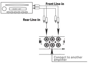
Output connection:Again, high current barrier strip terminals are provide for connection to the loud speaker system.In the stereo mode, connect the left speaker lead to the left terminal and the right speaker leads to the right terminal. Be sure to observe polarity.In the Bridged/Mono mode, connect the speaker (+) lead to the R+ terminal and the speaker(-) lead to the L- terminal.Stereo/Mono configuration may be used bu utilizing the above wiring simultaneously.(For satellite subwoofer or satellite / center).
Note: Mono mode Is designed for 4-8 ohm load and will not support a 2 ohm load.
Stereo Amplifier System
Connect the two pairs of output terminals to corresponding Left/Right speakers:
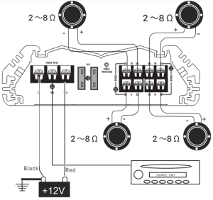
Mono Amplifier System:This unit bridgeable from a 2 channel amplifier to a one channel amplifier. The ideal speaker impedance for optimum operation is 4 ohms. The amplifier will provide stable operation between 2 and 8 ohms loads.
The minimum recommended speaker load is 2 ohm s for each channel in stereo mode. When operating in the bridged mode, the minimum recommended speaker load is 4 ohms for each bridge channel. Operation of the amplifier below this impedance load can damage both the amplifier and you speaker, and will void your warranty.
Power OnLed-PowerWhen the unit is properly grounded, have proper power, and is receiving remoter power sign al, the red LED will light up indicating power conditions are correct.
Pretection Led-PowerWhen the unit is protection, the protection LED will light up.
TROUBLE SHOOTING
No Audio
- Low or no remote turn-on voltage: check remote connections at the amplifier and source unit.
- Blown amplifier fuse: replace with a new fast-blow fuse (same rating).
- Power wires not connected: check battery and ground wiring at the amplifier and check the battery connections.
- Speaker leads shorted: check speaker continuity to ground; it should not show acommon ground.
- Speakers not connected or are blown: check speaker connections at the amplifier; measure coil impedance.
Distorted audio
- Gain is not properly set or the speaker cones are damaged.
- Review the instructions for setting the gain. Inspect each speaker cone for signs of damage, such as a frozen cone, burning smell, etc.
Features
- Digital pulse-width -modulated regulated power supply.
- Mosfet power supply devices.
- Fully complementary discrete audio stages .
- Direct coupled output stage.
- Discrete output transistors.
- Low overall negative feedback.
- bridgeable to Mono operation.
- Stereo /Mono setup simultaneously.
- 4 way protection circuit-thermal, current, D.C. Moffset, and over voltage.
- Soft start delay turn-on.
- Increased surface area and mass for continuous heat dissipation.
- LED power on indicator.
Specification
|
Output Power: |
SR4-1300 : 4xJ00W(4G RMS) / 4x16ow‹zn nMs › Bridged:2x320W(4£I RMS) |
|
SR4-1800 : 4x14Ow‹4n RMsj / 4x225W(2Ci RMS ) Bridged:2x45OW(4G RMS) |
|
|
THD: <O. 396 |
|
|
Frequency RESP: 10Hz 20kHz 12dB |
|
|
S/N Ratio: 90dB |
|
|
Input Sensitivity: 2OOmV 8V |
|
|
Bass Boost: 12dB |
|
|
Speaker Impedance: 2 8 CI |
|
|
Power Fuse: 35Ax2 ( Refer flank text) |
|
|
Dimension (HxWxL): |
SR4-1300 2.3”H x 7.25”W x 12.2”L |
|
SR4-1800 2.3”H x 7.25”W x 13.78″L |
|
|
Accessory: |
Screws Set & Spare Fuse |
![]()
[xyz-ips snippet=”download-snippet”]