![]()
![]() SR5-3500D5 Channel Amplifier(Analog and Digital System)Owner’s Manual
SR5-3500D5 Channel Amplifier(Analog and Digital System)Owner’s Manual
Features & Functions
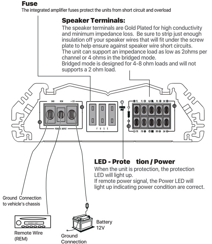
Power Terminals:B+I+12V. Connect the +12V pole of the power supply directly to the battery(+) position.GND. Connect the GND pole of the power supply directly to the (-) negative ground battery terminal of the car chassis.REM. Connect the “Remote” pole to the external switch for positive 12V ON/OFF. This may e connected to the power antenna of the turn-on lead of the head unit.Power Connection:For your convenience, high current barrier strip terminals are provided which allow the use of heavy gauge terminals and wire without splicing.B+1+12V Connect the +12V pole of the battery.GND. Connect the chassis ground of auto.REM. Connect to the remote turn-on lead of your head unit.
Note:Improper wiring connections can seriously damage amplifiers, accessories, or speakers, please follow instructions carefully. Disconnect the battery positive (+) before making any power connections to the amplifier.Make sure all connections are clean and secure and use grommets when going through the firewall and other metal bodywork.Always use the proper size fusing, with a fuse at the battery and the amplifier.(not supplied)
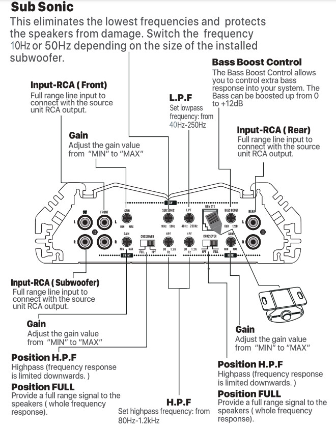
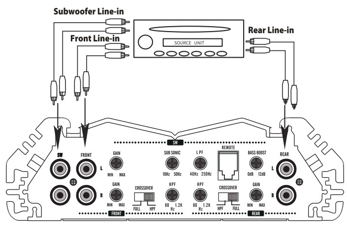
Input Connection:
Connect the pre-amp( low-level) outputs from your source unit or crossover to the RCA jacks labeled “input” on the amplifier. Be sure to route all signal cables away from power lines and use high-quality RCA cables to insure good signal transfer and to avoid noise from entering the system. In the Stereo mode, connect the left and right RCA plugs from the source unit to their appropriate input jacks. In the Mono/Bridged mode, connections may be made to right, left of both input jacks. If you are using a pre-amp device, such as the G & Designs Aa4X, connect the outputs of the front-end unit to the inputs of the pre-amp, then the outputs of the pre-amp to the inputs of the amplifier as per above.
Output connection: Again, high current barrier strip terminals are provided for connection to the loudspeaker system. In the stereo mode, connect the left speaker lead to the left terminal and the right speaker leads to the right terminal. Be sure to observe polarity. In the BridgedlMono mode, connect the speaker (+) lead to the R+ terminal and the speaker(-) lead to the L- terminal. StereolMono configuration may be used by utilizing the above wiring simultaneously. (For satellite subwoofer or satellite/center).Note: Mono mode is designed for 4-8 ohm load and will not support a 2-ohm load.
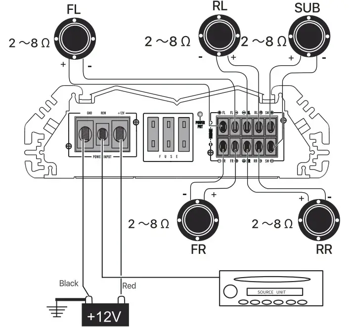
5 Channel Amplifier System:
Connect the two pairs of output and subwoofer terminals to corresponding Left/Right/subwoofer speakers:
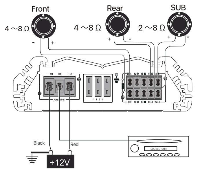
 2 Channel Amplifier System:
This unit is bridgeable from a 4.1 channel amplifier to a 2.1 channel amplifier. The ideal speaker impedance for optimum operation is 4 ohms. The amplifier will provide stable operation between 2 and 8 ohms loads. When operating in the bridged mode, the minimum recommended speaker load is 4 ohms for each bridge channel. Operation of the amplifier below this impedance load can damage both the amplifier and your speaker and will void your warranty.
TROUBLESHOOTING
No Audio
- Low or no remote turn-on voltage: check remote connections at the amplifier and source unit.
- Blown amplifier fuse: replace with a new fast-blow fuse (same rating).
- Power wires not connected: check battery and ground wiring at the amplifier and check the battery connections.
- Speaker leads shorted: check speaker continuity to the ground; it should not show common ground.
- Speakers not connected or are blown: check speaker connections at the amplifier; measure coil impedance.
Distorted audio
- Gain is not properly set or the speaker cones are damaged.
- Review the instructions for setting the gain. Inspect each speaker cone for signs of damage, such as a frozen cone, burning smell, etc.
Features:
- Full Range 2 ohm Stable 5-Channel Amplifier
- RMS Power Rating:4 ohms:100 watts x 4 charts, 350W x Sub than.2 ohms:150 watts x 4 chans., 500W x Sub than.Bridged, 4 ohms: 300 watts x 2 then., 500W x Sub than.
- Total power output: 2200 watts
- Pulse Width Modulated MOSFET power supply
- Wired remote bass level control included
- LEI) power (green) and protect (red) indicators
- Soft start turn-on
- 5/3 channel operation
- 3-way protection circuitry (thermal, overload, and speaker short protection)
- Dual speaker terminals simplify the hookup of multiple speakers
- Heavy-duty aluminum alloy heat-silk
- Input sensitivity: 200mV – 6V
- Variable high-pass filter. 80-1200 Hz, 12 dB/octave
- Variable low-pass filter:40 – 250 Hz, 12 dB/octave
- Variable Bass Boost: 0 to +12 dB bass boost
Specification:
| Output Power: | 4x140W +1x300W(40 RMS)4x220W +1X500W(20 RMS )Bridged:2x440W(40 RMS) +1x500W(20 RMS ) |
| THD: | <0.3% |
| Frequency RESP: | 10Hz — 20kHz ±2dB |
| S/N Ratio: | ≥90 |
| Input Sensitivity: | 200mV ∼8V |
| Bass Boost: | 12dB |
| Speaker Impedance: | 2 ∼8 0 |
| Power Fuse: | 40Ax2 ( Refer flank text) |
| Dimension (FixWxL): | SRS-3500D 2.2″H x 8.5″W x16.1″L |
| Accessory: | Screws Set & Spare Fuse |
[xyz-ips snippet=”download-snippet”]