Quick Start GuideO2BLP1M
Warning and Caution
- If the product does not work properly, please contact your dealer or the nearest service center. Never attempt to disassemble the camera yourself. Any unauthorized changes or modifications could void the warranty.
- Do not allow water or liquid intrusion into the camera.
- All installation and operation here should conform to local electrical safety codes. Make sure the device is firmly installed on the wall or ceiling.
- Do not use a camera beyond the specified voltage range.
- Do not drop the camera or subject it to physical shock.
- Avoid touching the camera lens.
- If cleaning is necessary, please use a cleaning cloth to wipe it gently.
- Do not aim the camera at the sun or extremely bright light sources.
- Do not place the camera in extremely hot or cold environments and dusty and damp locations. Do not expose it to high electromagnetic radiation.
- Do not block any ventilation.
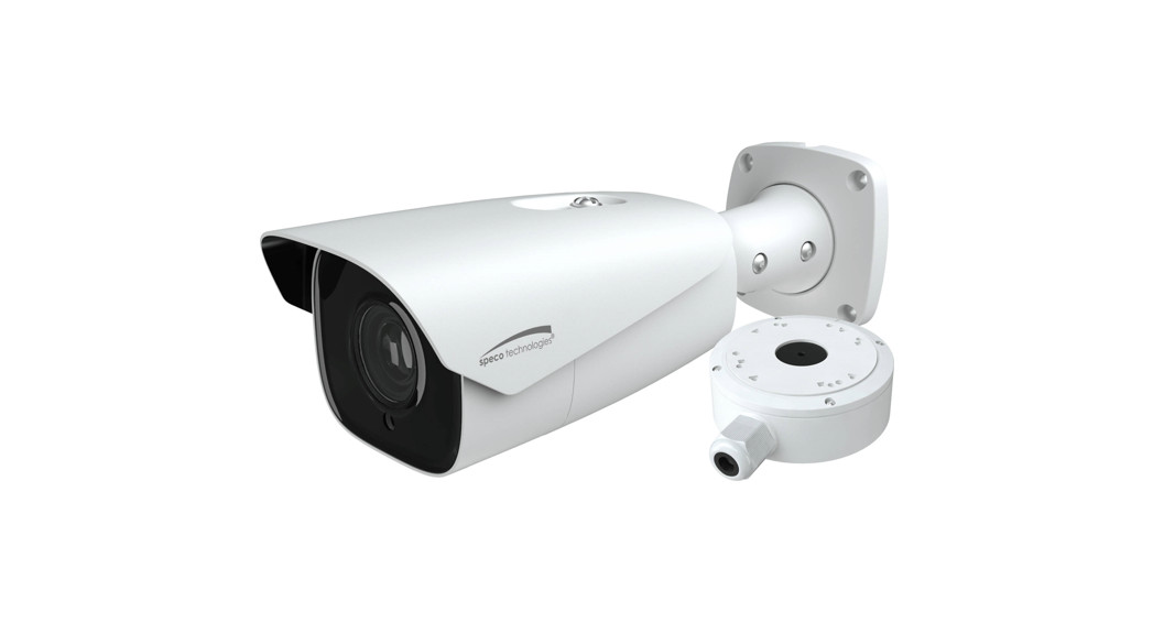
Package

Overview
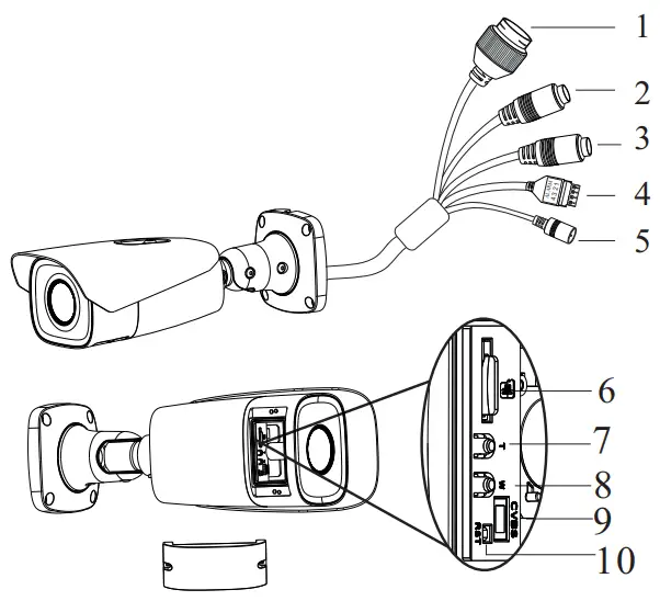
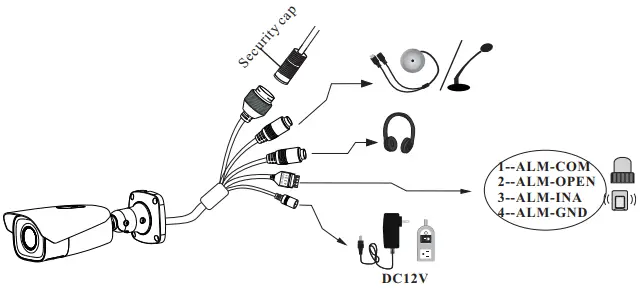
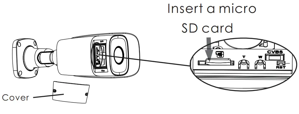
| 1 Ethernet Connector2 MIC-Audio Input3 HP-Audio Output4 Alarm Output/Input5 Power Connector * | 6 Micro SD Card Slot7 Zoom +*8 Zoom -*9 CVBS output (unavailable)10 Reset |
* 1It is recommended to install the security cap for outdoor installation.* 2 If the PoE switch is used to power the camera, a DC12V power supply is not required.
 * 1 It is recommended to install the security cap for outdoor installations.* 2 DC 12V power supply is not required if a PoE switch or injector is used to power the camera.
Connecting Network Cable
① Loosen the nut from the main element.② Run the network cable (without RJ 45 connector) through both elements.Then crimp the cable with RJ 45 connector.③ Connect the cable to the hermetic connector. Then tighten the nut and the main cover.
Installation
- SD Card InstallationOpen the cover of the camera as shown in the following figure and then insert a micro SD card. After that, install the cover back to the camera (Note that the cover shouldn’t be installed unevenly).
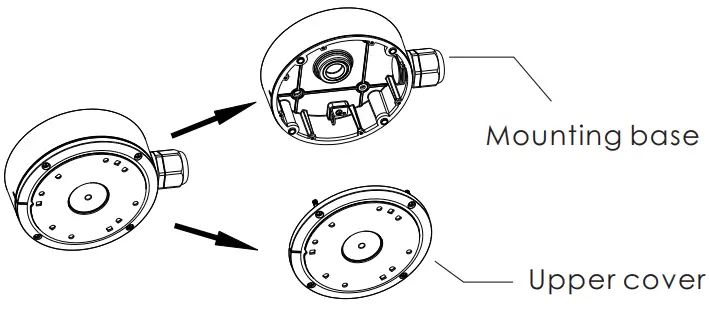
- Camera Installation with a Junction Box* Before you start, please make sure that the wall or ceiling is strong enough to withstand three times the weight of the camera and junction box.① Open the mounting base and the upper cover of the junction box.② Install the mounting base of the junction box onto the wall by using the screws provided.③ Fix the mounting base of the camera to the upper cover of the junction box.④ Route the cables through the cable hole and connect the camera. Then install the camera onto the mounting base of the junction box. ⑤Three-axis Adjustment-Before adjustment, preview the image of the camera on a monitor and then loosen the fixed screws to adjust the camera according to the figure below to get an optimum angle.
 ② Install the mounting base of the junction box onto the wall by using the screws provided.③ Fix the mounting base of the camera to the upper cover of the junction box.
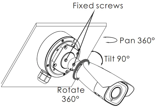
Configuration requirements of the camera and surrounding area
Note: The following installation requirements are based on optimum conditions, your license capture rate may vary depending on speed, lighting, position, license plate designs, and other factors.
- The monitoring image shall try to cover the lane, entering/exiting vehicles and these vehicles’ plate numbers shall be always seen in the video.
- Try to avoid the objects that will block the camera, such as pillars, obstacles, doors, etc.
- Avoid scenes with many trees or other moving objects (like humans, non-motor vehicles).
- The monitoring road shall be straight within 165ft in front of/behind the location of the camera installation and make sure the camera points at the front or rear of the vehicle.
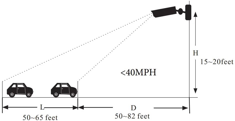
Overhead Monitoring
- The installation height (H) shall range from 15 ~ 20ft.
- The distance D (between the location of the camera installation and the captured area) shall range from 50 ~ 82ft. This distance (D) depends on the installation height, usually 3 or 4 times as far as the installation height (H)
- The distance of the captured area (L) shall be from 50 ~ 65ft.
- The depression angle of the camera shall range from 10° to 15°.
- If the camera is installed on the side of the road, the pan angle of the camera shall range from 0° to 20°.
- If the camera is installed right above the middle of the road, the pan angle of the camera shall range from -10° to 10°.
 The depression angle of the camera shall range from 10° to 15°.
Entrance & Exit Monitoring
- The installation height (H) shall range from 4.2ft to 5ft.
- The distance D (between the location of the camera installation and the captured area) shall range from 8.2ft to 10ft.
- The distance of the captured area (L) shall be from 5ft to 6.5ft.
- The depression angle of the camera shall range from 0° to 5°.
- The pan angle of the camera shall range from 5° to 20°.
The tilt angle of the license plateAfter the camera is installed, you can log in to the web client and view whether the license plate tilts in the video. The tilt angle shall range from -5° to 5°.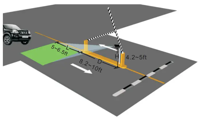 If the captured license plate doesn’t meet the above requirement, you can adjust the pan angle of the camera to correct it.
Web Operation and Login
 report this ad
IP Scanner can search for the device on the local network.
- Operation① Make sure that the camera and the PC are connected to the same local network.The camera is set to DHCP by default.② Install IP Scanner from the CD and run it after installation.③ In the device list, you can view the IP address, model number, and MAC address of each device. Select the applicable device and double-click to open up the web viewer. You can also manually enter the IP address in the address bar of the web browser.
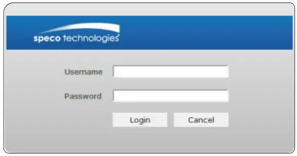
The login interface is shown above. The default user name is admin and the password is 1234. After logging in, follow the directions to install applicable plugins.
[xyz-ips snippet=”download-snippet”]