![]()
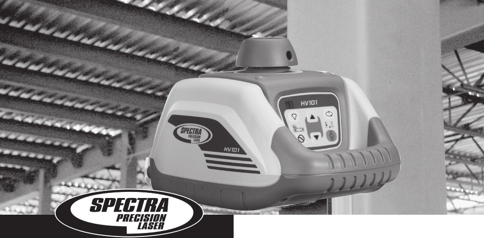
HV101User Guide
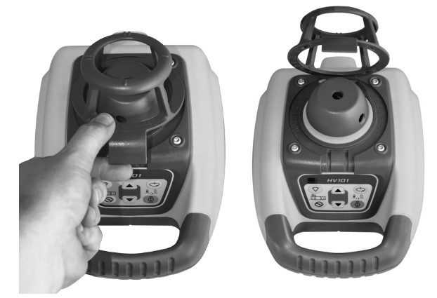
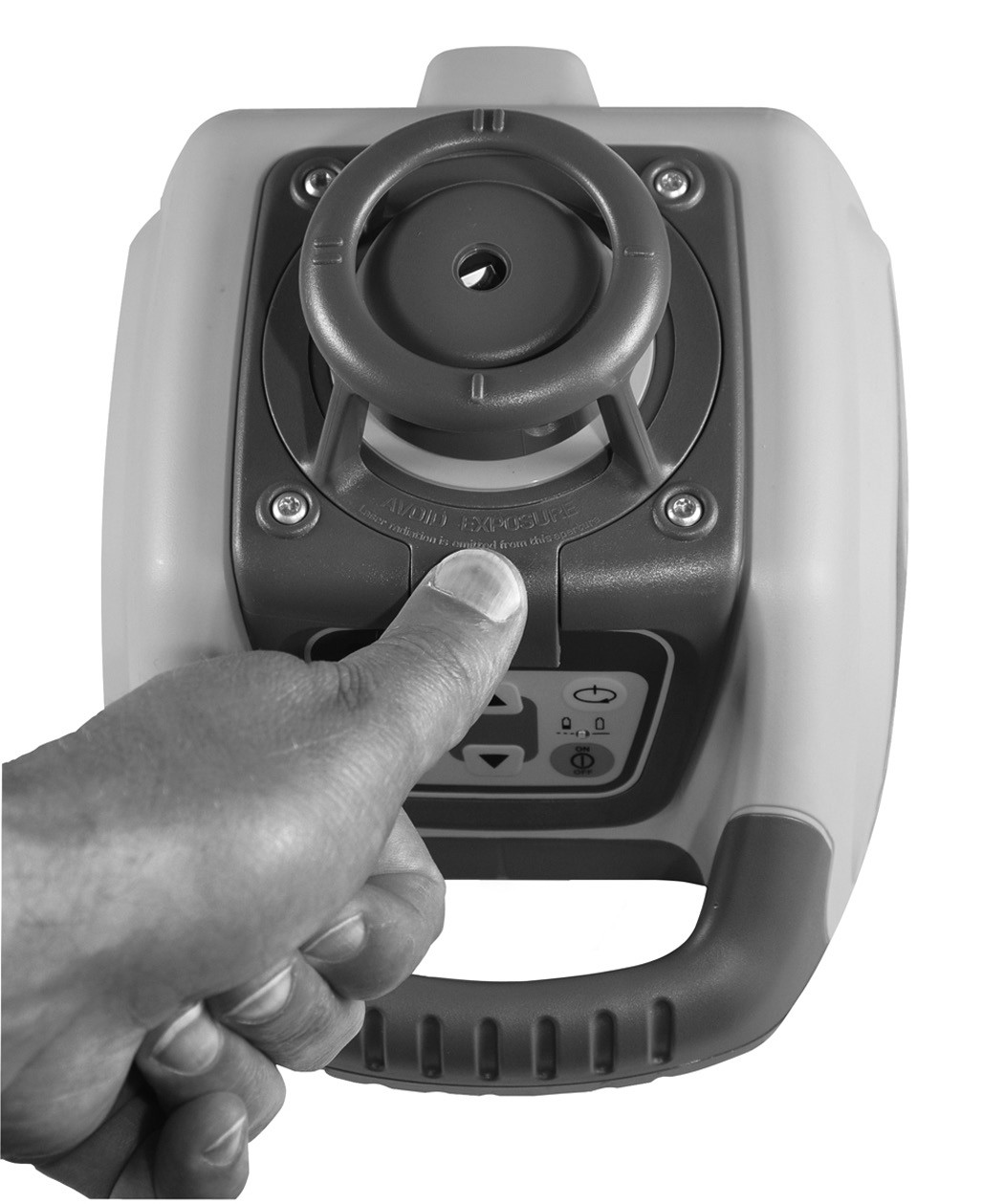
The protective rotor cage is removable for a full 360-degree coverage
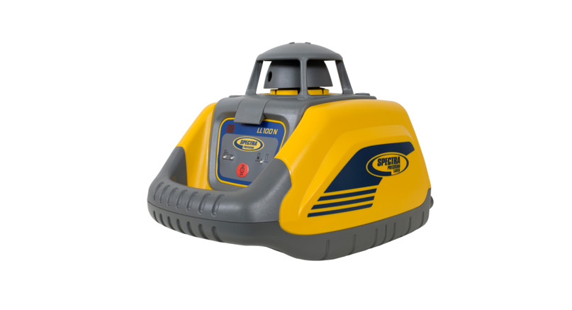
Thank you for choosing one of the Spectra Precision Lasers from the Trimble family of precision horizontal/vertical lasers.The HV101 is a simple-to-use laser that allows you to take accurate horizontal/vertical measurements, 90°-and plumb point transfer.
FOR YOUR SAFETY
 For hazardless and safe operation, read all the user guide instructions.
- Use of this product by people other than those trained on this product may result in exposure to hazardous laser light.
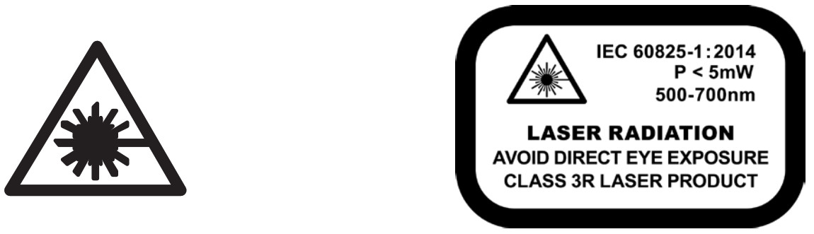
- Do not remove warning labels from the unit.
- The HV101 is Class 3A/3R (< 5mW, 600 … 680 nm).
- Never look into the laser beam or direct it to the eyes of other people.
- Always operate the unit in a way that prevents the beam from getting into people‘s eyes.
- If initial service is required, which results in the removal of the outer protective cover, removal must only be performed by factory-trained personnel.
Caution: Use of other than the described user and calibration tools or other procedures may result in exposure to hazardous laser light.Caution: Using different than described at the HV101 user guide, may result in unsafe operation.
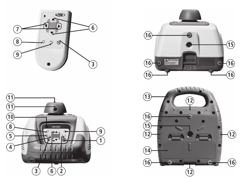
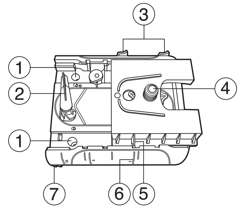
COMPONENTS
1 Power Button2 Battery LED3 Manual/Standby Button4 Leveling LED5 Manual/HI-Warning LED6 Up and Down Arrow Buttons7 Left and Right arrow Buttons8 Zone-Scan Button9 Rotation Control Button10 Infrared-receiver for remote control11 Rotor/Beam Exit12 Cross Mark Notches13 Handle14 Battery compartment/door15 5/8x 11 Tripod Mounts16 Rubber feet
How to Use the Laser SystemPowering the LaserBatteriesInstalling BatteriesOpen the battery door using your fingers, a coin or a screwdriver.Insert batteries into the housing so that the negative poles are on the bigger battery spiral spring.Push down on the battery door until the latch “clicks” into position.
Laser SetupPosition the laser horizontally or vertically (tripod mount and rubber feet downward!) on a stable platform, wall mount or tripod at the desired elevation. The laser recognizes automatically whether it is used horizontally or vertically when switched on.Turning On/Off the LaserPress the power button 1 to turn on the laser.Note: The laser always powers up in the automatic self-leveling mode. The LEDs (2, 4, and 5) are turned on for 2 seconds.
The laser is level when the leveling indicator 4 is no longer flashing (once every second).For the first five minutes after the laser self-levels, the LED 4 lights solid then flashes every four seconds to let you know the laser is still level.After turning on the laser and after self-leveling, the laser starts in the last chosen mode. The „set and forget“ function turns on the laser beam while scan size, beam position, and rotation speed are adjusted.If the laser is positioned beyond its a self-leveling range of ±8%, the laser beam, and manual and leveling indicators flash simultaneously. Turn the unit off, reposition the laser within the self-leveling range and turn it on again.
Note: If the laser is out of its self-leveling range and remains out of it for more than 10 minutes, the unit shuts down completely.Note: After the laser has been level for more than 5 minutes in horizontal mode and the rotor is rotating at 600 rpm, the HI (height of instrument) alert activates. If the laser is disturbed (tripod bumped, etc.) so that when it re-levels the laser beam elevation changes by more than 3 mm (1/8 in.), the HI alert shuts down the laser and rotor, and the red LED flashes two times per second (twice the manual-mode rate). To restore level, turn the laser off and on. After the laser has re-leveled, check your initial reference elevation. In order to switch the laser off, press the power button again.
Activating/Deactivating Standby ModeStandby mode is a power-saving feature that conserves laser battery life.Press and hold the laser’s or remote control’s manual button for 3 seconds to activate standby mode.Note: When standby mode is activated, the laser beam, rotor, self-leveling system, and LEDs shut down, but the HI alert remains activated.To let you know that the laser is in standby mode, the battery LED flashes every 4 seconds.To deactivate standby mode and restore full operation of the laser, press and hold the laser’s or remote control’s manual button for 3 seconds.The laser and all other functions turn on again.
Using the Rotation ModeThe rotation control button 9 sets the laser into rotation mode. Scan mode is stopped.Repeatedly pressing the button toggles the laser through 0, 50, 200, 600 RPM.The laser always powers up in the last selected rotation speed.Note: The zone-scan button can be used to stop the beam’s rotation.
Using the Pointing ModeLaserIf the beam’s rotation is stopped during horizontal operation, the up and down arrow buttons at the laser can be pressed to move the beam (small line) gradually counterclockwise or clockwise (360°).During vertical operation, the up /down arrow buttons can be used to move the small line left/right.Remote ControlIf the beam’s rotation is stopped during horizontal operation, the remote control’s left and right arrow buttons can be pressed to move the beam gradually counterclockwise or clockwise (360°).During vertical operation, the left /right arrow buttons can be used to move the beam counterclockwise/clockwise.By pressing and holding either button, the movement of the small line will be accelerated.Note: The first 4 seconds, the beam moves in fine pointing speed, then it moves in course speed.
Using the Scan ModePressing and releasing the zone-scan button at the laser or remote control sets the laser to scan mode. Rotation mode is stopped.The unit starts at an opening angle of approx. 3 degrees. Repeatedly pressing the zone-scan button increases the angle to approx. 8, 45, 90, 180 and 0 degrees.Pressing the up or down button at the laser or the right or left arrow button at the remote control moves the scan zone clockwise or counterclockwise until the desired position is reached.Note: In self-leveling mode (horizontal), the up arrow button increases the zone-scan size (up to 180º), and the down arrow button decreases the size (down to 3º).Note: The rotation control button can be used to stop the scan mode.
Using the Manual ModePressing the manual button on the laser or the remote control changes the laser from automatic self-leveling mode to Manual mode. Manual mode is indicated by the flashing (once every second) red LED 5.In Manual mode (horizontal), the Y-axis can be sloped by pressing the Up- and Down-Arrow-buttons on the laser‘s keypad or the remote control. Additionally, the X-axis can be sloped by pressing the Left- and right arrow-buttons on the remote control.In vertical mode, the up and down arrow buttons align the laser beam to the right/left side, and the left and right arrow buttons at the remote control adjust the slope of the laser beam.To resume automatic self-leveling mode, press the manual button again.
Using the Y- or X-Axis Single Slope ModeTo activate the Y-axis single slope mode, press the manual button (1 second) after the up arrow button at the laser or remote control has been pressed and released. This is indicated by the simultaneously flashing red 5 and green 4 LEDs (once every second).
In Y-axis single slope mode, the Y-axis can be sloped by pressing the Up- and Down-Arrow-buttons on the laser or the remote control, while the X-axis remains in automatic self-leveling mode (e.g. when setting up sloped ceilings or driveways).To activate the X-axis single slope mode, press the manual button (1 second) after the right arrow button at the remote control has been pressed and released. This is indicated by the simultaneously flashing red 5 and green 4 LEDs (every 3 seconds).In X-axis single slope mode, the X-axis can be sloped by pressing the right- and left-Arrow-buttons on the remote control, while the Y-axis remains in automatic self-leveling modeTo resume automatic self-leveling mode, press the manual button again.
APPLICATIONS
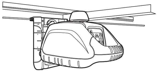
InteriorAcoustical Ceilings
- Determine and mark the finished ceiling height and securely install the first piece of wall molding to this height.
- Attach the laser onto the wall molding by sliding the wall mount clamp over the wall molding and pulling down the locking lever.
- To adjust the elevation, release the elevation clamp, slide the laser to the zero (0) mark on the scale (wall molding elevation), and lock the elevation clamp.Note: To minimize accidental dropping, insert a ceiling wire through one of the holes and twist the wire.
Drywall and Partitions
- Attach the laser to the sliding bracket.
- Place the laser over the near wall-control point.
- Use the up/down arrow button to point the beam towards the far wall-control point.
- Go to the far wall-control point and use the remote control to adjust the line of the laser until the laser beam is aligned to the mark.
- Install the track or mark the track line on both the floor and ceiling for future track installation.
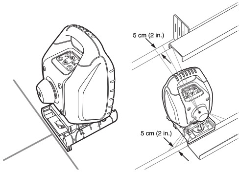
Transferring Plumb Points to the CeilingThe origin of the laser beam is located directly above the horizontal tripod mount and the height of the vertical tripod mount.In order to transfer a marked point from the bottom to the ceiling, there are cross center marks 12 at the lower part of the unit‘s bottom housing. Using these marks, the unit may be set up with the two axes X and Y above two crossed chalk marks, for example.For better installation of the unit above a mark on the floor, just mark 2 rectangular lines through this point.
General ConstructionDetermining the Height of Instrument (HI)The height of instrument (HI) is the elevation of the laser’s beam.The HI is determined by adding the grade-rod reading to a benchmark or known elevation.
- Set up the laser and place the grade rod on a job-site benchmark (BM) or known elevation.
- Slide the receiver up/down the grade rod until it shows an on-grade reading.
- Add the grade-rod reading to the benchmark to determine the height of the instrument.
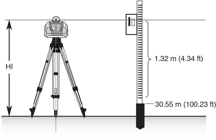
Example: Benchmark = 30.55 m (100.23 ft)Rod reading = +1.32 m (+4.34 ft)Height of instrument = 31.87 m (104.57 ft)Use this HI as a reference for all other elevations.
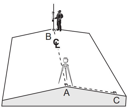
Using the Y-Axis Single Slope Mode
- Set up the laser over the reference point (A).
- Look over the rotor to align the laser to the desired direction hub in the axis that is supposed to be used in automatic self-leveling mode. Turn the laser on the tripod until it is properly aligned.
- Attach a receiver to a grade rod. Set the grade rod on the self-leveling axis direction hub to check the laser’s elevation (B).Note: Use this HI as a reference for checking the alignment of the laser after setting the slope for the other axis.
- Activate the Y-axis single slope mode by pressing the manual button (1 second) after the up arrow button at the laser or remote control has been pressed and released.
- Check the laser’s elevation on the slope axis directly in front of the laser.

- Set the grade rod on the slope axis direction hub to adjust the laser’s elevation without changing the height of the receiver on the grade rod (C).
- Press the up and down arrow buttons until you get an on-grade reading on the receiver.
- Recheck the laser’s elevation in automatic self-leveling axis using the HI in step 3 (B).If the HI has been changed, rotate the laser on the tripod until you get an on-grade reading again. Make sure, you DON’T change the height of the receiver on the grade rod.
CALIBRATION
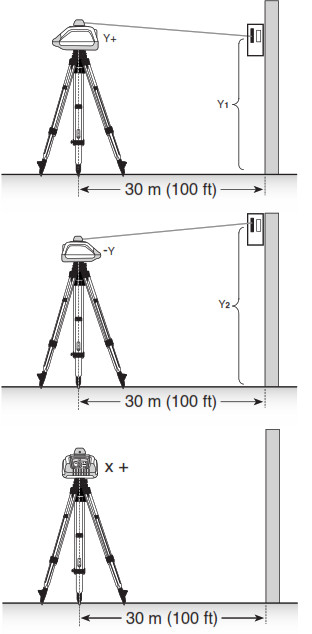
Checking Calibration of the Y- and X-Axes
- Set up the laser 30 m (100 ft) from a wall and allow it to level.
- Raise/lower the receiver until you get an on-grade reading for the +Y/axis. Using the on-grade marking notch as a reference, make a mark on the wall.Note: For increased precision, use the fine-sensitivity setting (1.5 mm/1/16 in.) on the receiver.
- Rotate the laser 180° (-Y axis toward the wall) and allow the laser to re-level.
- Raise/lower the receiver until you get an on-grade reading for the –Y/axis. Using the on-grade marking notch as a reference, make a mark on the wall.
- Measure the difference between the two marks. If they differ more than 6 mm at 30 m (1/4 inch at 100 feet), the laser needs calibrating.
- After checking the Y-axis, rotate the laser 90°. Repeat the above starting with the + X axis facing the wall.
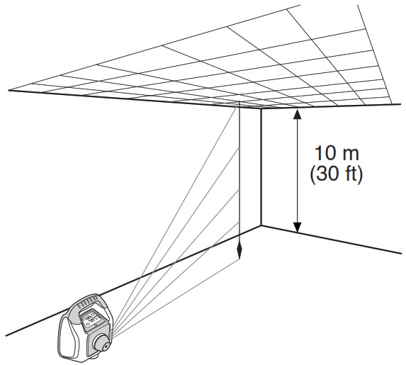
Z (Vertical) AxisChecking Calibration of the Z (Vertical) AxisTo check vertical calibration, you need a plumb bob with at least 10 m (30 ft) of string.
- Suspend the plumb bob from the ceiling of a room whose ceiling height is at least 10 m (30 ft).
- Stop the beam’s rotation and set up the laser in vertical so that the laser beam strikes the top of the string.
- Using the left/right arrow button at the remote control, guide the beam from the top of the string to the bottom of it.
- Look for any deviation in the beam from the top of the string to the bottom of it.If the deviation is more than 2 mm (3/32 in.), the vertical axis needs calibrating.
Note: If calibration is required, please, refer to the calibration instructions on our Trimble website www.trimble.com/support.shtml
M101 WALL MOUNT
- Nail Hole – allows you to hang the wall mount onto a nail or screw.
- Locking Lever – opens/closes the wall mount clamp.
- Latches for elevation clamp– opens/closes so that the sliding bracket can be attached to the wall mount.
- Sliding bracket with 5/8“ –11 Laser Mount – lets you connect the laser to the wall mount and holds the sliding bracket in place after it has been positioned along the elevation scale.
- Reading Edge – allows you to adjust the laser position appropriately for your application needs.
- Elevation Scale – provides graduated marks that indicate the position of the laser relative to the wall molding height. The adjustment range on the scale is from 3 cm (1 ¼ in.) above wall-molding height to 5 cm (2 in.) below it. (The „–2“ position is aligned with the horizontal centerline at the ceiling target.)
- Clamp – opens/closes so that the wall mount can be attached to wall molding or floor track.
PROTECTING THE UNIT
Do not expose the unit to extreme temperatures or temperature changes (do not leave inside the car).The unit is very robust and can resist damage if dropped even from tripod height. Before continuing your work, always check the leveling accuracy. See Checking Calibration section.The laser is water protected and can be used indoors and outdoors.
CLEANING AND MAINTENANCE
Dirt and water on the beam exits of laser or prism will influence beam quality and operating range considerably.Remove dirt on the housing with a lint-free, warm, wet and smooth cloth. Do not use harsh cleansers or solvents.Allow the unit to air dry after cleaning it.
PROTECTING THE ENVIRONMENT
The unit, accessories and packaging ought to be recycled. All plastic parts are marked for recycling according to material type.Do not throw used batteries into the garbage, water or fire. Remove them in compliance with environmental requirements.Notice to Our European Union CustomersFor product recycling instructions and more information, please go to: http://www.trimble.com/Corporate/Environmental_Compliance.aspx
Instructions for Return to ERFC:
- WEEE is to be shipped to the ERFC, clearly stating WEEE on the delivery note and/or packaging
- Specific product number and serial number information is not required
- Additional return authorization from Trimble Support is not required
- Delivery Address:Trimble Europe B.V. WEEE RecyclingC/O Menlo logisticsGate 19 to 26Meerheide 435521 DZEerselThe Netherlands
Confirmation of receipt of the returned WEEE will not be provided by the ERFC
Warranty
Trimble warrants the HV101 to be free of defects in material and workmanship for a period of 2 years. Trimble or its authorized service center will repair or replace, at its option, any defective part, or the entire product, for which notice has been given during the warranty period. If required, travel and per diem expenses to and from the place where repairs are made will be charged to the customer at the prevailing rates. Customers should send the product to Trimble Inc. or the nearest authorized service center for warranty repairs or exchange, freight prepaid. Any evidence of negligent, abnormal use, accident, or any attempt to repair the product by other than factory-authorized personnel using Trimble certified or recommended parts, automatically voids the warranty. Special precautions have been taken to ensure the calibration of the laser; however, calibration is not covered by this warranty. Maintenance of the calibration is the responsibility of the user. The foregoing states the entire liability of Trimble regarding the purchase and use of its equipment. Trimble will not be held responsible for any consequential loss or damage of any kind. This warranty is in lieu of all other warranties, except as set forth above, including any implied warranty merchantability or fitness for a particular purpose, are hereby disclaimed. This warranty is in lieu of all other warranties, expressed or implied.
TECHNICAL DATA
| Leveling accuracy 1,3: | ± 1 mm/10 m, 1/8“ @ 100 ft, 20 arc seconds |
| Rotation: | 4 speed levels, appr. 0/50/200/600 rpm |
| Operational area1,2: | appr. 150 m (500 feet) radius with detector |
| Laser type: | red diode laser 635 nm |
| Laser class: | Class 3R, <5mW |
| Self-leveling range: | appr. ± 5° |
| Leveling time: | appr. 30 sec |
| Leveling indicators: | LED flashes |
| Laser beam diameter1: | appr. 5 mm |
| Operating range using remote control: | up to 30m (100 ft) |
| Power supply: | 2 x 1.5V Mono cells type D (LR20) |
| Battery life1: | alkaline: 50 hours; NiMH: 45 hours |
| Dust- and waterproof: | IP54 |
| Operating temp.: | 23°F…113°F (-5°C … 45°C) |
| Storage temp.: | -4°F…158°F (-20°C … 70°C) |
| Tripod attachments: | 5/8 x 11 horizontally and vertically |
| Weight: | 1.5 kg (3.3 lbs) |
| Low voltage indication: | flashing/shining of the battery indicator |
| Low voltage disconnection: | unit shuts off |
1) at 21° Celsius2) under optimal atmospheric circumstances3) along the axis
DECLARATION OF CONFORMITY
WeTrimble Kaiserslautern GmbH declare under our sole responsibility that the product HV101 to which this declaration relates is in conformity with the following standards IEC/EN/UL 61010; IEC/EN 60825; EN 61000-4-2, 2001; EN 61000-6-3:2001; EN 55022, 2003; EN 61000-6-2:2005; EN 61000-4-3, 2003 following the provisions of directive Electromagnetic compatibility 89/336/EEC.The managing director
Electro-Magnetic CompatibilityDeclaration of ConformityThis digital apparatus does not exceed the Class B Limits for radio noise for digital apparatus set out in the Radio Interference Regulations of the Canadian Department of Communications.This device complies with part 15 off the FCC rules. Operation is subject to the condition that this device does not cause harmful interference.
Note: The product been tested and found to comply with the limits for a Class B digital device, pursuant to part 15 of the FCC rules. These limits are designed to provide reasonable protection against harmful interference in a residential installation. The product generates, uses and can radiate radio frequency energy and, if not installed and used in accordance with the instructions, may cause harmful interference to radio or television reception, which can be determined by turning the product off and on. The user is encouraged to try to eliminate the interference by one or more of the following measures:
• Reorient or relocate the receiving antenna.• Increase the separation between the product and the receiver.• For more information, consult your dealer or an experienced radio/television technician.Caution: Changes or modifications to the product that are not expressly approved by Trimble could void authority to use the equipment.
Service and Customer Advice
North AmericaTrimble Construction Division5475 Kellenburger RoadDayton, Ohio 45424-1099U.S.A.(800) 538-7800 (Toll Free)+1-937-245-5600 Phone+1-937-233-9004 Fax
EuropeTrimble GmbHAm Prime Parc 1165479 RaunheimGERMANY+49-6142-2100-0 Phone+49-6142-2100-550 Fax
Latin AmericaTrimble Navigation Limited6505 Blue Lagoon DriveSuite 120Miami, FL 33126U.S.A.+1-305-263-9033 Phone+1-305-263-8975 Fax
Africa & Middle EastTrimble Export Middle-EastP.O. Box 17760Jebel Ali Free Zone, DubaiUAE+971-4-881-3005 Phone+971-4-881-3007 Fax
Asia-PacificTrimble NavigationAustralia PTY LimitedLevel 1/120 Wickham StreetFortitude Valley, QLD 4006AUSTRALIA+61-7-3216-0044 Phone+61-7-3216-0088 Fax
ChinaTrimble BeijingRoom 2805-07, Tengda Plaza,No. 168 Xiwai StreetHaidian DistrictBeijing, China 100044+86 10 8857 7575 Phone+86 10 8857 7161 Faxwww.trimble.com.cn
![]()
Trimble Construction Division5475 Kellenburger RoadDayton, Ohio 45424U.S.A.+1-937-245-5600 Phone
© 2017, Trimble Inc. All rights reservedPN Q103740 (Rev. E) (10/17)
[xyz-ips snippet=”download-snippet”]