![]()

https://www.horizonhobby.com/product/SPMAR10100T.html
SPMAR10100T
AR10100T 10 Channel Telemetry Receiver User Guide
NOTICEAll instructions, warranties, and other collateral documents are subject to change at the sole discretion of Horizon Hobby, LLC. For up-to-date product literature, visit horizonhobby.com or towerhobbies.com and click on the support or resources tab for this product.
MEANING OF SPECIAL LANGUAGEThe following terms are used throughout the product literature to indicate various levels of potential harm when operating this product:WARNING: Procedures, which if not properly followed, create the probability of property damage, collateral damage, and serious injury OR create a high probability of superficial injury.AUCTION: Procedures, which if not properly followed, create the probability of physical property damage AND a possibility of serious injury.NOTICE: Procedures, which if not properly followed, create a possibility of physical property damage AND a little or no possibility of injury.
Age Recommendation: Not for children under 14 years. This is not a toy.
![]() WARNING: Read the ENTIRE instruction manual to become familiar with the features of the product before operating. Failure to operate the product correctly can result in damage to the product, personal property and cause serious injury.This is a sophisticated hobby product. It must be operated with caution and common sense and requires some basic mechanical ability. Failure to operate this Product in a safe and responsible manner could result in injury or damage to the product or other property. This product is not intended for use by children without direct adult supervision. Do not attempt disassembly, use with Incompatible components, or augment product in any way without the approval of Horizon Hobby, LLC. This manual contains instructions for safety, operation, and maintenance. It is essential to read and follow all the instructions and warnings in the manual, prior to assembly, setup or use, in order to operate correctly and avoid damage or serious injury.
WARNING: Read the ENTIRE instruction manual to become familiar with the features of the product before operating. Failure to operate the product correctly can result in damage to the product, personal property and cause serious injury.This is a sophisticated hobby product. It must be operated with caution and common sense and requires some basic mechanical ability. Failure to operate this Product in a safe and responsible manner could result in injury or damage to the product or other property. This product is not intended for use by children without direct adult supervision. Do not attempt disassembly, use with Incompatible components, or augment product in any way without the approval of Horizon Hobby, LLC. This manual contains instructions for safety, operation, and maintenance. It is essential to read and follow all the instructions and warnings in the manual, prior to assembly, setup or use, in order to operate correctly and avoid damage or serious injury.
![]() WARNING AGAINST COUNTERFEIT PRODUCTS. Always purchase from a Horizon Hobby, LLC authorized dealer to ensure authentic high-quality Spektrum product. Horizon Hobby, LLC disclaims all support and warranty with regards to, but not limited to, compatibility and performance of counterfeit products or products claiming compatibility with DSM or Spektrum technology.NOTICE: This product is only intended for use with unmanned, hobby-grade, remote-controlled vehicles. Horizon Hobby disclaims all liability outside of the intended purpose and will not provide warranty service related thereto.
WARNING AGAINST COUNTERFEIT PRODUCTS. Always purchase from a Horizon Hobby, LLC authorized dealer to ensure authentic high-quality Spektrum product. Horizon Hobby, LLC disclaims all support and warranty with regards to, but not limited to, compatibility and performance of counterfeit products or products claiming compatibility with DSM or Spektrum technology.NOTICE: This product is only intended for use with unmanned, hobby-grade, remote-controlled vehicles. Horizon Hobby disclaims all liability outside of the intended purpose and will not provide warranty service related thereto.
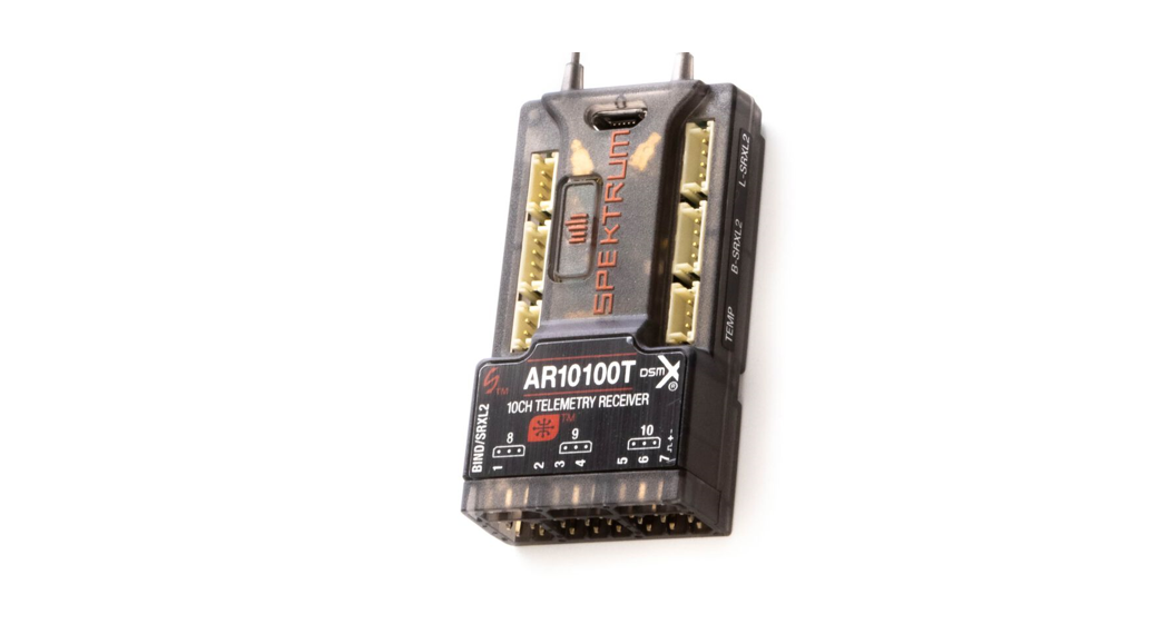
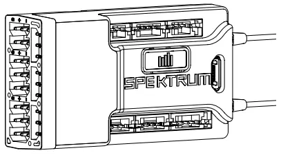
AR10100T Telemetry Receiver
The Spektrum ™ AR10100T receiver is a full-range telemetry receiver featuring DSM® technology. It is compatible with all Spektrum ™ aircraft radios that support DSM2® and DSMX® technology.
Perform the failsafe setup for the AR10100T receiver through a compatible Spektrum Transmitter with forwarding Programming. The Spektrum PC Programmer can be used for firmware updates.
|
SPECIFICATIONS |
AR10100T |
| Type | DSM2/DSMX 10 CH Telemetry Receiver |
| Application | Air |
| Channels | 10 |
| Receivers | 1 |
| Remote Receiver (not included) | SRXL2™ Optional Remote Receiver (SPM9747, SPM4651T) |
| Modulation | DSM2/DSMX |
| Data Flight Log Compatible | No |
| Telemetry | Integrated |
| Bind Method | Bind Button |
| Failsafe | Yes |
| Band | 2.4GHz |
| Dimensions (LxWxH) | 55 x 30 x 15mm |
| Weight | 0.6 oz (18g) |
| Input Voltage | 3.5–9V |
| Resolution | 2048 |
| Antenna Length | 155mm and 186mm |
| Connector | Micro USB |
Smart Throttle
The AR10100T receiver throttle port includes Smart Throttle. When equipped with Smart Throttle the normal servo connector delivers the throttle signal to the ESC, plus the ESC can send telemetry data like voltage and current back to the receiver. The AR10100T receiver throttle port will automatically detect when a Smart Throttle compatible ESC is plugged in and the throttle port will begin to operate in Smart Throttle mode.ESCs with Smart Throttle and IC3® and IC5® connectors can also pass along battery data from compatible Spektrum Smart batteries.If a standard ESC or servo is plugged into the throttle port on the AR10100T receiver, the throttle port will operate normally (PWM signal) like any conventional RC system. The AR10100T receiver is compatible with the Spektrum Avian line of ESCs for Smart Throttle.
For Smart Throttle to function you must have a Smart Throttle ESC paired with a Smart Throttle telemetry receiver, and a Spektrum DSMX transmitter with telemetry. An update for your transmitter may be required or Smart features. Visit www.spektrumrc.com to register and update your transmitter.
AR10100T Receiver Installation
For optimum RF link performance, mount the antennas for optimal signal reception accounting for all possible aircraft attitudes and positions. Orient the antennas perpendicular to each other; typically vertical and horizontal and at different angles.
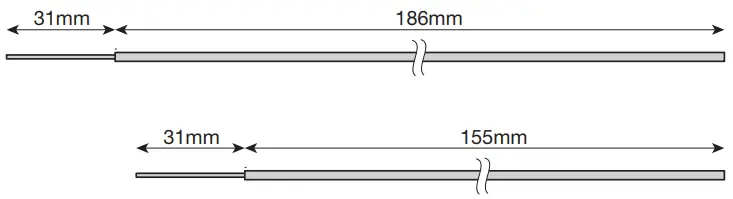
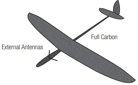
Optional SRXL2 Remote Receiver (not included): If using an optional SRXL2 remote receiver, apply double-sided foam tape and mount it perpendicular to and at least 2 inches away from the main receiver’s antenna.Airplanes with significant carbon fiber construction can create an RF shielding effect, reducing range. The AR10100T is designed to overcome these critical RF issues in carbon airplanes by outfitting the aircraft with two external antennas at specific points that will ensure secure RF coverage from all angles of the aircraft.The AR10100T incorporates two feeder antennas; one antenna is 6.10 inches (155 mm) and the second antenna is 7.32 inches (186 mm). They are designed to be easily mounted through the fuselage in carbon airplanes. Each feeder antenna includes a coaxial portion and an exposed 31mm tip antenna. The last 31mm is the active portion of the antenna.
Installing the ReceiverInstall the receiver in the normal position recommended by the airplane’s manufacturer. Double-sided tape or foam can be used to secure the receiver in place.TIP: The hard case can be removed to help the AR10100T fit into a slim, carbon fuselage. It is recommended to cover the bare receiver in heat shrink.Mounting the AntennasTo install the antennas, drill two 1/16-inch holes in the desired antenna mounting positions.
Slide the feeder antennas through the holes until the 31mm tip, and about 2mm of coaxial, completely exit the fuselage. Use a drop of CA or tape to fix the antenna to the fuselage.IMPORTANT: Ensure that the 31mm active portion of each antenna tip is fully exposed.TIP: Use the optional (sold separately) Antenna Exit Guides to safely mount the antennas outside of the fuselage.IMPORTANT: If the antenna is to be mounted internally (in the front of a 2.4GHz fuse), the coaxial can be taped into position. Ensure the 31mm tip is located at least 2 inches from any significant metal or carbon structure.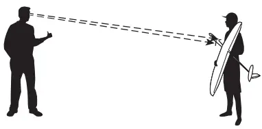
Check that at least one antenna will always be in the RF visual line of sight of the transmitter (e.g. not blocked by carbon fiber structures) in all attitudes. This can easily be visualized by having a helper stand about 20 feet away and rotate the airplane in all attitudes, confirming that there is a direct line between you and at least one receiver antenna that isn’t blocked by carbon fiber structure.
Binding
The AR10100T receiver must be bound to your transmitter before it will operate. Binding is the process of teaching the receiver the specific code of the transmitter so it will only connect to that specific transmitter. When new out of the package, the AR10100T will automatically go into bind mode the first time it is poweredon.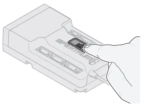
- Connect up to two optional SRXL2 remote receivers (SPM9747 or SPM4651T) and any telemetry sensors to the main receiver.
- Push and hold the bind button on the receiver while turning the receiver on. Release the bind button once the orange LED starts to flash continuously, indicating that the receiver is in bind mode.TIP: It is still possible to use a bind plug in the BIND port if desired. This can come in handy if the receiver needs to be mounted in a location that is difficult to access, in which case a servo extension may be used for finding. If using a bind plug, remove after binding to prevent the system from entering bind mode the next time the power is turned on.
- Put your transmitter in bind mode.
- The binding process is complete when the orange LED on the receiver is solid.
Failsafe
In the unlikely event that the radio link is lost during use, the receiver will enable the selected failsafe mode. Smart Safe + Hold Last is the default setting on the AR10100T. Preset Failsafe and SAFE Failsafe are only available through forwarding programming.SmartSafe + Hold LastIf loss of signal occurs, SmartSafe™ technology moves the throttle channel to its preset failsafe position (low throttle) that was set during binding. All other channels will hold their last position. When the receiver detects the signal from the transmitter, normal aircraft operation resumes.
Preset FailsafeWith preset failsafe, you can set the specific control surface positions you want to use if the signal is lost. When the receiver detects the signal from the transmitter, normal aircraft operation resumes. Only available through forwarding ProgrammingTesting FailsafeSecure the aircraft on the ground and remove the propeller. Test Failsafe settings by turning the transmitter RF output off and noting how the receiver drives the control surfaces.
Receiver Power Only
- If the receiver is turned when no transmitter signal is present, the throttle channel will not have a control signal to avoid operating or arming the electronic speed control.
- All other channels have no output until the receiver has linked to the transmitter.
Forward Programming
Verify your transmitter is updated your transmitter to the latest Spektrum AirWare™ software to take advantage of forwarding Programming. See your transmitter manual for updating instructions.In your transmitter menu select Forward Programming -> Settings ->
- Select Failsafe -> Select each channel and assign it to Preset or Hold Last. When you select a different channel for Output, a new group of settings appears.Capture Failsafe Positions ->Hold the control sticks in the desired failsafe positions and select Apply. Channel selections must be individually set in forwarding Programming to apply for the preset positions or each channel will default to Hold Last. The value captured will be reflected in the position shown for each channel.
- Initiate Receiver Bind ModeGives you the option of putting the receiver into Bind Mode from this menu.
Receiver Power System Requirements
Inadequate power systems that are unable to provide the necessary minimum voltage to the receiver during light have become the number one cause of in-flight failures. Some of the power system components that affect the ability to properly deliver adequate power include:
- Receiver battery pack (number of cells, capacity, cell type, state of charge)
- The ESC’s capability to deliver current to the receiver in electric aircraft
- The switch harness, battery leads, servo leads, regulators, etc.The AR10100T has a minimum operational voltage of 3.5 volts; it is highly recommended the power system be tested per the guidelines below.
Recommended Power System Test GuidelinesIf a questionable power system is being used (e.g. small or old battery, ESC that may not have a BEC that will support high-current draw, etc.), it is recommended that a voltmeter be used to perform the following tests.View the receiver voltage during this test on your transmitter’s telemetry screen, load the control surfaces (apply pressure with your hand) while monitoring the voltage at the receiver. The voltage should remain above 4.8 volts even when all servos are heavily loaded.
How QuickConnect ™ Technology Work
- When the receiver voltage drops below 3.5 volts, the system ceases to operate.
- When power is restored, the receiver immediately attempts to reconnect.
- If the transmitter was left on, the system reconnects typically in about 4/100 a second.QuickConnect is designed to allow you to fly safely through most short-duration power interruptions, however, the root cause of these interruptions must be corrected before the next flight to prevent a crash.
NOTICE: If a brownout occurs in flight it is vital that the cause of the brownout be determined and corrected.IMPORTANT: When using Y-harness or servo extensions with Spektrum equipment, do not use reversing harnesses. Using reversing Y-harnesses or servo extensions may cause servos to operate erratically or not function at all.
Flight Log
Flight Log data can help you optimize the control link for your aircraft. Flight Log data is displayed on elementary capable Spektrum transmitters.Using the Flight Log
| A – Fades on the main receiver | B – Fades on the remote receiver |
| L – Fades on the remote receiver | R – Not available on AR10100T |
| F – Frame losses | H – Holds |
FadesRepresents the loss of one bit of information on one receiver. Fades are used to evaluate the performance of each individual receiver. If any single receiver displays higher fade values it should be inspected and the antenna repositioned to optimize the RF link.
Frame LossA-frame loss occurs when one complete data packet is missed. A single frame loss does not represent a loss of control, but frame losses should be monitored. In the air, it’s normal to experience as many as 100 frame losses per minute of flight. On the ground, the number of frame losses will be higher because the signal is hampered by earth and moisture.
HoldA Hold occurs when 45 consecutive frame losses occur. This takes about one second, and in this event, the receiver moves the channel outputs to the failsafe settings. If a hold ever occurs, it’s important to re-evaluate the system and check every component. If your system displays a hold taking place, diagnose the cause and resolve the issue before flying again.It is normal to see a hold logged if you power OFF your transmitter and back ON.IMPORTANT: The Spektrum Flight Log (SPM9540) is not compatible with the AR10100T receiver.
Range Testing
Before each flying session, and especially with a new model, it’s important to perform a range check. All Spektrum aircraft transmitters incorporate a range testing system, which reduces the output power to allow a range check.
- With the model resting on the ground, stand approximately 100 feet (30 meters) away from the model.
- Face the model with the transmitter in your normal flying position and put your transmitter into range test mode.
- You should have total control of the model in range test mode at 100 feet.
If control issues exist, call Horizon Product Support for further assistance.
Advanced Range TestingThe Standard Range Testing procedure is recommended for most sport aircraft. For sophisticated aircraft that contain significant amounts of conductive materials (e.g. turbine powered jets, scale aircraft with metalized finishes, aircraft with carbon fuselages, etc.), the following advanced range check will confirm that all receivers in the system are operating optimally as installed. This advanced range check allows the RF performance of each receiver to be evaluated independently. A telemetry-equipped Spektrum Transmitter is required for the advanced range test.
- Stand approximately 100 feet away from the model.
- Face the model with the transmitter in your normal flying position and put your transmitter into range test mode.
- Have a helper position the model in various orientations (nose up, nose down, nose toward the transmitter, nose away from the transmitter, etc.).
- Observe the telemetry on your transmitter. Note any orientations that cause higher fades or frame loss values. Perform this step for at least one minute.
- Re-position any antennas related to higher fades as necessary.
- Re-test to verify satisfactory results.
- Repeat as necessary.
After one minute, advanced testing should yield:H − 0 holdsF – less than 10 frame lossesA, B, L – Fades will typically be less than 100. It is important to compare the relative frame losses. If an articular receiver has a significantly higher frame loss value (2 to 3X) then the test should be redone. If the same results occur, move the offending receiver to a different location.TIP: Use the fade values for A to investigate the telemetry link performance.
Telemetry
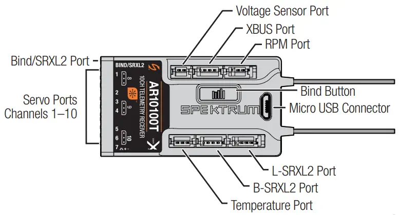
The AR10100T features full-range telemetry and will provide receiver battery voltage, flight log data, and various and altitude data without any additional sensors. The altitude and vertical speed (variometer) sensor (SPMA9589) functions are already integrated into the AR10100T. Additional telemetry devices such as voltage sensors can be connected to the volt port, a temperature sensor can be added in the temp port, an RPM sensor can be added in the RPM port, and XBUS telemetry sensors can be connected through the XBUS connector. Every XBUS telemetry device has two XBUS ports, and XBUS telemetry sensors can be connected in a daisy chain in any order.See www.spektrumrc.com for more information about telemetry accessories.
|
Optional Accessories |
|
| SPMA3065 | USB Programming Cable |
|
Telemetry Sensors and Accessories |
|
| SPMA9571 | DSMX/DSMR Telemetry Temperature Sensor |
| SPMA9574 | Aircraft Telemetry Airspeed Indicator |
| SPMA9589 | Aircraft Telemetry Altitude and Variometer Sensor |
| SPMA9587 | Aircraft Telemetry GPS Sensor |
| SPMA9604 | Aircraft Telemetry Receiver Battery Energy Sensor |
| SPMA9605* | Aircraft Telemetry Flight Pack Batt Energy Sensor |
| SPMA9551 | 12″ Aircraft Telemetry Extension |
| SPMA9552 | 24″ Aircraft Telemetry Extension |
*For use with electric power system batteries that are separate from the receiver battery(s).
Troubleshooting Guide
| Problem | Possible Cause | Solution |
|
Aircraft will not respond to throttle but responds to other controls |
Throttle not at idle and/or throttle trim too high | Reset controls with throttle stick and throttle trim at low- est setting |
| Throttle servo travel is lower than 100% | Make sure throttle servo travel is 100% or greater | |
|
The throttle channel is reversed |
(With battery disconnected from aircraft) Reverse throttle channel on the transmitter | |
| Motor disconnected from ESC | Make sure the motor is connected to the ESC | |
|
Aircraft will not Bind (during binding) to the transmitter |
Transmitter too near aircraft during the binding process |
Move powered transmitter a few feet from aircraft, disconnect and reconnect flight battery to aircraft |
| Aircraft or transmitter is too close to a large metal object, wireless source, or another transmitter | Move aircraft and transmitter to another location and at- tempt binding again | |
| The bind plug is not in- stalled correctly in the bind port | Install bind plugin bind port and bind the aircraft to the transmitter | |
| Flight battery/transmitter battery charge is too low | Replace/recharge batteries | |
| Bind button not held long enough during the binding process | Power off and repeat bind process |
| Problem | Possible Cause | Solution |
|
Aircraft will not connect (after binding) to the transmitter |
Transmitter too near aircraft during the connecting process |
Move powered transmitter a few feet from aircraft, disconnect and reconnect flight battery to aircraft |
| Aircraft or transmitter is too close to a large metal object, wireless source or another transmitter | Move aircraft and transmitter to another location and attempt connecting again | |
| Bind plug left installed in bind port | Rebind transmitter to the aircraft and remove the bind plug before cycling power | |
| Aircraft bound to different model memory (ModelMatchTM radios only) | Select correct model memory on the transmitter | |
| Flight battery/Transmitter battery charge is too low | Replace/recharge batteries | |
| The transmitter may have been bound to a different aircraft using a different DSM protocol |
Bind aircraft to the transmitter |
|
|
The control surface does not move |
The control surface, control horn, linkage, or servo damage | Replace or repair damaged parts and adjust controls |
| Wire damaged or connections lose | Do a check of wires and connections, connect or replace as needed | |
| The transmitter is not bound correctly or the incorrect airplanes were selected | Re-bind or select correct airplanes in the transmitter | |
| Flight battery charge is low | Fully recharge flight battery | |
| BEC (Battery Elimination Circuit) of the ESC is damaged | Replace ESC |
1-Year Limited Warranty
What this Warranty Covers—Horizon Hobby, LLC, (Horizon) warrants to the original purchaser that the product purchased (the “Product”) will be free from defects in materials and workmanship for a period of 1 year from the date of purchase.What is Not Covered—This warranty is not transferable and does not cover (I) cosmetic damage, (ii) damage due to acts of God, accident, misuse, abuse, negligence, commercial use, or due to improper use, installation, operation or maintenance, (iii) modification of or to any part of the Product, (iv) attempted service by anyone other than a Horizon Hobby authorized service center, (v) Product not purchased from an authorized Horizon dealer, (vi) Product not compliant with applicable technical regulations, or (vii) use that violates any applicable laws, rules, or regulations.OTHER THAN THE EXPRESS WARRANTY ABOVE, HORIZON MAKES NO OTHER WARRANTY OR REPRESENTATION, AND HEREBY DISCLAIMS ANY AND ALL IMPLIED WARRANTIES, INCLUDING, WITHOUT LIMITATION, THE IMPLIED WARRANTIES OF NON-INFRINGEMENT, MERCHANTABILITY, AND FITNESS FOR A PARTICULAR PURPOSE. THE PURCHASER ACKNOWLEDGES THAT THEY ALONE HAVE DETERMINED THAT THE PRODUCT WILL SUITABLY MEET THE REQUIREMENTS OF THE PURCHASER’S INTENDED USE.
Purchaser’s Remedy—Horizon’s sole obligation and purchaser’s sole and exclusive remedy shall be that Horizon will, at its option, either (i) service, or (ii) replace, any Product determined by Horizon to be effective. Horizon reserves the right to inspect any and all Product(s) involved in a warranty claim. Service or replacement decisions are at the sole discretion of Horizon. Proof of purchase is required for all warranty claims. SERVICE OR REPLACEMENT AS PROVIDED UNDER THIS WARRANTY IS THE PURCHASER’S SOLE AND EXCLUSIVE REMEDY.Limitation of Liability—HORIZON SHALL NOT BE LIABLE FOR SPECIAL, INDIRECT, INCIDENTAL OR CONSEQUENTIAL DAMAGES, LOSS OF PROFITS OR PRODUCTION OR COMMERCIAL LOSS IN ANY WAY, REGARDLESS OF WHETHER SUCH CLAIM IS BASED IN CONTRACT, WARRANTY, TORT, NEGLIGENCE, STRICT LIABILITY OR ANY OTHER THEORY F LIABILITY, EVEN IF HORIZON HAS BEEN ADVISED OF THE POSSIBILITY OF SUCH DAMAGES. further, in no event, shall the liability of Horizon exceed the individual price of the Product on which liability is asserted. As Horizon has no control over use, setup, final assembly, modification, or misuse, no liability shall be assumed nor accepted for any resulting damage or injury. By the act of use, setup, or assembly, the user accepts all resulting liability. If you as the purchaser or user are not prepared to accept the liability associated with the use of the Product, the purchaser is advised to return the Product immediately in new and unused condition to the place of purchase.Law—These terms are governed by Illinois law (without regard to conflict of law principles). This warranty gives you specific legal rights, and you may also have other rights which vary from state to state. Horizon reserves the right to change or modify this warranty at any time without notice.
WARRANTY SERVICESQuestions, Assistance, and Services—Your local hobby store and/or place of purchase cannot provide warranty support or service. Once assembly, setup, or use of the Product has been started, you must contact your local distributor or Horizon directly. This will enable Horizon to better answer your questions and service you in the event that you may need any assistance. For questions or assistance, please visit our website at www.horizonhobby.com, submit a Product Support Inquiry, or call the toll-free telephone number referenced in the Warranty and Service Contact Information section to speak with a Product Support representative.Inspection or Services—If this Product needs to be inspected or serviced and is compliant in the country you live and use the Product in, please use the Horizon Online Service Request submission process found on our website or call Horizon to obtain a Return Merchandise Authorization (RMA) number. Pack the Product securely using a shipping carton. Please note that original boxes may be included, but are not designed to withstand the rigors of shipping without additional protection. Ship via a carrier that provides tracking and insurance for lost or damaged parcels, as Horizon is not responsible for merchandise until it arrives and is accepted at our facility. An Online Service Request is available at http://www.horizonhobby.com/content/ service-center_render-service-center. If you do not have internet access, please contact Horizon Product Support to obtain an RMA number along with instructions for submitting your product for service. When calling Horizon, you will be asked to provide your complete name, street address, email address, and phone number where you can be reached during business hours. When sending products into Horizon, please include your RMA number, a list of the included items, and a brief summary of the problem. A copy of your original sales receipt must be included for warranty consideration. Be sure your name, address, and RMA number are clearly written on the outside of the shipping carton.
NOTICE: Do not ship LiPo batteries to Horizon. If you have any issues with a LiPo battery, please contact the appropriate Horizon Product Support office.
Warranty Requirements—For Warranty consideration, you must include your original sales receipt verifying the proof-of-purchase date. Provided warranty conditions have been met, your Product will be serviced or replaced free of charge. Service or replacement decisions are at the sole discretion of Horizon.Non-Warranty Service—Should your service not be covered by warranty, service will be completed and payment will be required without notification or estimate of the expense unless the expense exceeds 50% of the retail purchase cost. By submitting the item for service you are agreeing to payment of the service without notification. Service estimates are available upon request. You must include this request with your item submitted for service. Non-warranty service estimates will be billed a minimum of ½ hour of labor. In addition, you will be billed for return freight. Horizon accepts money orders and cashier’s checks, as well as Visa, MasterCard, American Express, and Discover cards. By submitting any item to Horizon for service, you’re agreeing to Horizon’s Terms and Conditions are found on our websitehttp://www.horizonhobby.com/content/service-center_render-service-center.
ATTENTION: Horizon service is limited to Product compliant in the country of use and ownership. If received, a non-compliant Product will not be serviced. Further, the sender will be responsible for arranging return shipment of the un-serviced Product, through a carrier of the sender’s choice and at the sender’s expense. Horizon will hold non-compliant Products for a period of 60 days from notification, after which they will be discarded.
Warranty and Service Contact Information
| Country of Purchase | Horizon Hobby | Contact Information | Address |
|
United States of America |
Horizon Service Center (Repairs and Repair Requests) | servicecenter.horizonhobby.com/RequestForm/ |
2904 Research Rd Champaign, Illinois, 61822 USA |
| Horizon Product Support
(Product Technical Assistance) |
[email protected]. | ||
| 877-504-0233 | |||
| Sales | [email protected] | ||
| 800-338-4639 | |||
|
EU |
Horizon Technischer Service | [email protected] | Hanskampring 9
D 22885 Barsbüttel, Germany |
| Sales: Horizon Hobby GmbH | +49 (0) 4121 2655 100 |
FCC Information
CONTAINS FCC ID: BRWSPMAR10100T Supplier’s Declaration of ConformitySpektrum AR10100T Telemetry Receiver (SPMAR10100T)
This device complies with part 15 of the FCC Rules. Operation is subject to the following two conditions: (1) This device may not cause harmful interference, and (2) this device must accept any interference received, including interference that may cause undesired operation.
![]() CAUTION: Changes or modifications not expressly approved by the party responsible for compliance could void the user’s authority to operate the equipment.
CAUTION: Changes or modifications not expressly approved by the party responsible for compliance could void the user’s authority to operate the equipment.
NOTE: This equipment has been tested and found to comply with the limits for a Class B digital device, pursuant to part 15 of the FCC Rules. These limits are designed to provide reasonable protection against harmful interference in a residential installation. This equipment generates, uses, and can radiate radio frequency energy and, if not installed and used in accordance with the instructions, may cause harmful interference to radio communications. However, there is no guarantee that interference will not occur in a particular installation. If this equipment does cause harmful interference to radio or television reception, which can be determined by turning the equipment off and on, the user is encouraged to try to correct the interference by one or more of the following measures:
- Reorient or relocate the receiving antenna.
- Increase the separation between the equipment and receiver.
- Connect the equipment into an outlet on a circuit different from that to which the receiver is connected.
- Consult the dealer or an experienced radio/TV technician for help.Horizon Hobby, LLC2904 Research Rd., Champaign, IL 61822Email: [email protected]Web: HorizonHobby.com
IC Information
CONTAINS IC: 6157A-SPMAR10100T CAN ICES-3 (B)/NMB-3(B)This device contains license-exempt transmitter(s)/receivers(s) that comply with Innovation, Science, and Economic Development Canada’s license-exempt RSS(s). Operation is subject to the following 2 conditions:This device may not cause interference.This device must accept any interference, including interference that may cause undesired operation of the device.
Compliance Information for the European Union

EU Compliance Statement:Spektrum AR10100T Telemetry Receiver (SPMAR10100T)Hereby, Horizon Hobby, LLC declares that the device is in compliance with the following: EU Radio Equipment Directive 2014/53/EU; RoHS 2 Directive 2011/65/EU; RoHS 3 Directive – Amending 2011/65/EU Annex II 2015/863.The full text of the EU declaration of conformity is available at the following internet address: https://www.horizonhobby.com/content/support-rendercompliance.
Wireless Frequency Range and Wireless Output Power:2404 – 2476 MHz 18.99dBmEU Manufacturer of Record:Horizon Hobby, LLC 2904 Research Road Champaign, IL 61822 USAEU Importer of Record:Horizon Hobby, GmbH Hanskampring 9 22885 Barsbüttel Germany
WEEE NOTICE:

This appliance is labeled in accordance with European Directive 2012/19/EU concerning waste of electrical and electronic equipment (WEEE). This label indicates that this product should not be disposed of with household waste. It should be deposited at an appropriate facility to enable recovery and recycling.

 report this ad
© 2021 Horizon Hobby, LLC.DSM, DSM2, DSMX, AS3X, SAFE, SRXL2, Spektrum AirWare, QuickConnect, ModelMatch, SmartSafe, Hangar 9, and the Horizon Hobby logo are trademarks registered trademarks of Horizon Hobby,LLC.The Spektrum trademark is used with permission of Bachmann Industries, Inc. All other trademarks, service marks and logos are property of their respective owners. US 9,930,567. US 10,419,970. US 10,849,013. Other patents are pending
References
RC Airplanes and Helicopters, RC Cars and Trucks, RC Boats, RC Radios | Horizon Hobby
RC Airplanes and Helicopters, RC Cars and Trucks, RC Boats, RC Radios | Horizon Hobby
RC Airplanes and Helicopters, RC Cars and Trucks, RC Boats, RC Radios | Horizon Hobby
RC Cars, RC Trucks, RC Airplanes, Model Trains, and Slot Cars at Tower Hobbies
RC Airplanes and Helicopters, RC Cars and Trucks, RC Boats, RC Radios | Horizon Hobby
RC Airplanes and Helicopters, RC Cars and Trucks, RC Boats, RC Radios | Horizon Hobby
Spektrum RC Transmitters and RC Electronics | Spektrum
Ferngesteuerte Flugmodelle, Autos, Trucks, Hubschrauber, Boote und Fernsteuerungen | Horizon Hobby
RC Airplanes & Helicopters, RC Cars & Trucks, RC Boats, RC Radios | Horizon Hobby
RC Cars, RC Trucks, RC Airplanes, Model Trains, and Slot Cars at Tower Hobbies
RC Airplanes and Helicopters, RC Cars and Trucks, RC Boats, RC Radios | Horizon Hobby
RC Airplanes and Helicopters, RC Cars and Trucks, RC Boats, RC Radios | Horizon Hobby
RC Cars, RC Trucks, RC Airplanes, Model Trains, and Slot Cars at Tower Hobbies
Spektrum RC Transmitters and RC Electronics | Spektrum
RC Airplanes and Helicopters, RC Cars and Trucks, RC Boats, RC Radios | Horizon Hobby
RC Airplanes and Helicopters, RC Cars and Trucks, RC Boats, RC Radios | Horizon Hobby
RC Airplanes and Helicopters, RC Cars and Trucks, RC Boats, RC Radios | Horizon Hobby
[xyz-ips snippet=”download-snippet”]