
![]()
SPEKTRUM AR8360T AS3X and SAFE Telemetry Receiver User Manual

NOTICEAll instructions, warranties and other collateral documents are subject to change at the sole discretion of Horizon Hobby, LLC. For up-to-date product literature, visit horizonhobby.com or towerhobbies.com and click on the support or resources tab for this product.
Meaning of Special Language
The following terms are used throughout the product literature to indicate various levels of potential harm when operating this product:
WARNING: Procedures, which if not properly followed, create the probability of property damage, collateral damage, and serious injury OR create a high probability of superficial injury.
CAUTION: Procedures, which if not properly followed, create the probability of physical property damage AND a possibility of serious injury.
NOTICE: Procedures, which if not properly followed, create a possibility of physical property damage AND a little or no possibility of injury.
 WARNING: Read the ENTIRE instruction manual to become familiar with the features of the product before operating. Failure to operate the product correctly can result in damage to the product, personal property and cause serious injury.
This is a sophisticated hobby product. It must be operated with caution and common sense and requires some basic mechanical ability. Failure to operate this Product in a safe and responsible manner could result in injury or damage to the product or other property. This product is not intended for use by children without direct adult supervision. Do not attempt disassembly, use with incompatible components or alter product in any way without the approval of Horizon Hobby, LLC. This manual contains instructions for safety, operation and maintenance. It is essential to read and follow all the instructions and warnings in the manual, prior to assembly, setup or use, in order to operate correctly and avoid damage or serious injury.
Age Recommendation: Not for children under 14 years. This is not a toy.
WARNING AGAINST COUNTERFEIT PRODUCTSAlways purchase from a Horizon Hobby, LLC authorized dealer to ensure authentic high-quality Spektrum product. Horizon Hobby, LLC disclaims all support and warranty with regards, but not limited to, compatibility and performance of counterfeit products or products claiming compatibility with DSM or Spektrum technology.
NOTICE: This product is only intended for use with unmanned, hobby-grade, remote-controlled vehicles and aircraft. Horizon Hobby disclaims all liability outside of the intended purpose and will not provide warranty service related thereto.
WARRANTY REGISTRATIONVisit www.spektrumrc.com/registration today to register your product.
AR8360T AS3X and SAFE Telemetry Receiver
The Spektrum™ AR8360T Receiver is full range with telemetry, and is compatible with all Spektrum™ DSM2® and DSMX® technology transmitters.
Perform the setup for the AR8360T receiver through a compatible Spektrum Transmitter with Forward Programming. The Spektrum PC Programmer can be used for firmware updates.
IMPORTANT: The AR8360T receiver only uses forward programming for the configuration, do not use the AS3X menu in the main transmitter menu.
WARNING: If equipped, the propeller should not be installed on the motor during the setup procedure. Only install the propeller once the throttle has been confirmed to operate correctly and the failsafe has been set. As an additional safety feature, we recommend the throttle cut is enabled. Throttle cut should be engaged any time the aircraft is powered on and not in operation. The motor will not rotate when throttle cut is in the ON position.
Specifications


Smart Throttle
With Smart Technology the normal servo connector delivers the throttle signal to the ESC, plus the ESC can send telemetry data like voltage and current back to the receiver. The AR8360T receiver throttle port (Channel 1 port only) will automatically detect when a Smart compatible ESC is connected. ESCs with Smart and IC series connectors can also pass along battery data from compatible Spektrum Smart batteries. Spektrum Avian™ ESCs are compatible with the AR8360T receiver for Smart Technology features.
For Smart to function you must have a Smart ESC paired with a Smart telemetry receiver, and a Spektrum DSMX transmitter with telemetry. An update for your transmitter may be required for Smart features. See www.spektrumrc.com to register and update your transmitter.
If a standard ESC or servo is plugged into the throttle port on the AR8360T receiver, the throttle port will operate normally (PWM signal) like any conventional RC system.
Telemetry
The AR8360T features full range telemetry and will provide receiver battery voltage, flight log data, vertical speed, and altitude data without any additional sensors. Additional telemetry devices such as voltage sensors can be connected to the volt port, and XBus telemetry sensors can be connected through the XBus connector. Every XBus telemetry device has two XBus ports, and XBus telemetry sensors can be connected in a daisy chain in any order.
The AR8360T is not compatible with the Spektrum Temperature Sensor (SPMA9571) See www.spektrumrc.com for more information about telemetry accessories
Installing the AR8360T Receiver
- Mount the receiver using double-sided servo tape. The receiver may be mounted upright, upside down or on its side, but it should be square with the fuselage in its mounting position. The receiver cannot be mounted at an odd angle.TIP: For SAFE setups, install the receiver as close to the center of gravity of the aircraft as practical.
- Connect the servos to their respective ports on the receiver using the chart below.
CAUTION: Incorrect installation of the receiver could cause a crash. Always perform a control surface check and AS3X control surface response test before flying a new setup, or after any setup changes.
DEFAULT CHANNEL ASSIGNMENTS
AR8360T Port AssignmentsBind/Prog/SRXL2= Bind, Aux Device Support, Program
- Throttle (Smart Throttle)
- Aileron
- Elevator
- Rudder
- Gear
- Aux 1
- Aux 2
- Aux 3
IMPORTANT: When using Y-harness or servo extensions with Spektrum equipment, do not use reversing harnesses. Using reversing Y-harnesses or servo extensions may cause servos to operate erratically or not function at all.
ANTENNA INSTALLATIONThe AR8360T receiver has coaxial style antennas. We recommend installing the antennas oriented 90º from each other and as far as possible from metal, batteries, carbon fiber or fuel tanks to maximize signal reception performance.
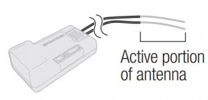
NOTICE: Do not cut, kink, or modify the antennas. Damage to the coaxial portion of an antenna will reduce the performance of the antenna. Shortening or cutting off the 31mm tip will reduce the range.
Transmitter and Receiver Binding
Programming the AR8360T receiver requires a Spektrum™ DSM2®/DSMX® compatible transmitter with Forward Programming.
The AR8360T receiver must be bound to your transmitter before it will operate. Binding is the process of teaching the receiver the specific code of the transmitter so it will only connect to that specific transmitter.
![]()
- Connect the optional SRXL2 remote receiver (SPM9747 or SPM4651T) if desired and any telemetry sensors to the main receiver.
- Push and hold the bind button on the receiver while turning the receiver on. Release the bind button once the orange LED starts to flash continuously, indicating the receiver is in bind mode.TIP: It is still possible to use a bind plug in the bind port if desired. This can come in handy if the receiver needs to be mounted in a location that is difficult to access, in which case a servo extension may be used for binding. If using a bind plug, remove after binding to prevent the system from entering bind mode the next time the power is turned on.
- Put your transmitter in bind mode
- The bind process is complete when the orange LED on the receiver is solid.
Failsafe
In the unlikely event the radio link is lost during use, the receiver will enable the selected failsafe mode. Smart Safe + Hold Last is the default failsafe mode on the AR8360T. Preset Failsafe and SAFE Failsafe modes are only available through Forward Programming.
SmartSafe + Hold LastIf loss of signal occurs, SmartSafe™ technology moves the throttle channel to the failsafe position (low throttle) set during binding. All other channels will hold their last position. When the receiver detects the signal from the transmitter, normal aircraft operation resumes.
Preset FailsafeWith preset failsafe, you can set the specific control surface positions you want to use if the signal is lost. When the receiver detects the signal from the transmitter, normal aircraft operation resumes.
Preset failsafe mode is only available through Forward Programming.
SAFE FailsafeSAFE Failsafe mode will work to automatically level your aircraft if the signal is lost. In the forward programming menu you can select the bank and pitch angles the aircraft will attempt to maintain during failsafe. We recommend setting bank and pitch angles so the aircraft flies a gentle gliding turn, preventing a flyaway. You must complete First Time SAFE Setup before this option is available.
SAFE Failsafe mode is only available through Forward Programming.
Testing FailsafeSecure the aircraft on the ground and remove the propeller. Test Failsafe settings by turning the transmitter RF output off and noting how the receiver drives the control surfaces.
Receiver Power Only
- The servo ports will not have a control signal if the receiver is turned on when no transmitter signal is present.
- All channels have no output until the receiver has linked to the transmitter.
Initial Setup
- Verify your transmitter is updated to the latest Spektrum AirWare™ software to take advantage of Forward Programming. See your transmitter manual for updating instructions.
- Install the receiver in your airplane.
- Bind the receiver to your transmitter.
- Complete the airplane setup on your transmitter including wing type, tail type, channelassignments, mixing, sub trim and travel the same as you would for any other aircraft without AS3X. Verify the center of gravity is correct and test fly your aircraft.
IMPORTANT: Do not use open mixes for flight control surfaces when setting up a model with the AR8360T for AS3X and SAFE. Only use wing and tail type options to configure flight controls, refer to your transmitter manual for more information about wing and tail type features.
AR8360T Receiver- Basic AS3X Setup
To use AS3X technology with the Spektrum AR8360T Receiver, the receiver needs to be set up with a compatible Spektrum transmitter.
1. Verify the basic setup and trim is accurate before attempting AS3X setup.
2. Forward Programming Setup: The receiver is directly configured through the Forward Programming menu.
- Low throttle is required to enter Forward Programming, we recommend enabling throttle cut and verify it prevents motor operation. The transmitter will not allow you to enter the Forward Programming menu unless throttle is low or throttle cut is activated.
- In your transmitter’s menu, select:Forward Programming -> Gyro Settings -> First Time SetupThe transmitter will prompt you for all setup steps.IMPORTANT: Before proceeding with setup, read every information screen that appears on your transmitter Select NEXT at the bottom of each page to continue.
- Follow the on-screen prompts to set the orientation. Select Continue to complete the two-step auto detection process, or select Set Orientation Manually. Verify the orientation is correct.
- You can assign any open channel to a switch (trimmer, knob, etc) for gain, and assign that channel for gain. You can assign a switch to a channel from the Forward Programming menu so you don’t have to exit the menu. We recommend using a trimmer, knob, or slider for gain, which will enable you to change the gain value on the fly. When the setup screens are complete select Apply.
3. AS3X Tuning Basics:
- Perform a control surface direction test, and AS3X reaction test.
- Test fly the airplane to verify the configuration. In-flight trim changes do not require any further updates. If the airplane needs sub-trim, travel or other setup changes in the transmitter programming, select Forward Programming -> Gyro Settings -> System Settings -> Relearn Servo Settings after making the needed changes.
- Oscillation occurs because the system is overshooting the correction, and will usually occur at higher speeds. If the airplane oscillates, immediately reduce speed and lower the gain value. Take note of which axis the aircraft oscillates around; you can increase or decrease the base gain values of each axis separately within the Forward Programming menu after landing.
- Increase the gain values until you find oscillation, and then reduce the gain to the highest setting that will not cause oscillation at any speed. This value will help the airplane track accurately and fly smoothly in wind and turbulence.
AS3X Reaction Test
This test ensures that the AS3X control system is functioning properly.
- Assemble the aircraft, bind your transmitter to the receiver, and complete the AS3X First Time Setup in the Forward Programming menu before performing this test.
- Raise the throttle above 25% to activate AS3X, then lower the throttle. Once the AS3X system is active, control surfaces move in response to aircraft movement. AS3X remains active until the battery is disconnected.
 CAUTION: Activate throttle cut to prevent motor operation during this test.
 - Move the aircraft as shown and ensure the control surfaces move in the direction indicated in the graphic. If the control surfaces do not respond as shown, do not fly the aircraft.
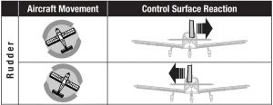
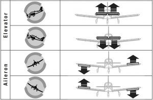
4. If the control surfaces do not respond as shown, review the receiver mounting orientation.
- In your transmitter’s menu selectForward Programming -> Gyro Settings -> System Setup -> Orientation
- Verify the receiver orientation matches the selected diagram. The image of the airplane is from the top. If your access to the receiver is from the bottom, remember the images on the screen need to match the way the receiver sits in the model when it is upright.
AR8360T Receiver- SAFE Setup
Setting up SAFE Technology on the AR8360T Receiver takes place in Forward Programming.
- Complete the AS3X setup and verify operation in flight.
- Forward Programming Setup: To add SAFE flight stabilization the Flight Modes on the receiver need to be configured.
- In your transmitter’s menu selectForward Programming -> Gyro Settings -> First Time SAFE SetupIMPORTANT: Before proceeding with setup, read every information screen that will appear on your transmitter screen.Select NEXT at the bottom of each page to continue.
- Select FM Channel-> Select the channel and switch you want to use for Flight Mode selection. You can select any channel that is not a control surface, throttle or gain. Select Continue.
- Position the model in a level flight attitude, then select Level Model and Capture Attitude to teach the receiver the baseline setting. For taildragger aircraft be sure to raise the tail so the fuselage is level.
- Assign SAFE to the desired flight modes. You can enable or disable SAFE for each flight mode. Take into account your flight mode switch position, and set the SAFE Mode as desired for the first switch position.• Envelope (Intermediate) mode does not use self leveling. The aircraft will fly like a normal AS3X setup, but it will be bank and pitch angle limited.• Self Leveling/Angle Demand will make the airplane return to level flight when the control stick is centered.
- Set the Angle Limits as desired for the first switch position. These values determine how far the aircraft will be allowed to pitch or bank.
- Move the Flight Mode switch to the other positions, a setup screen for SAFE Mode and Angle Limits will appear for each mode. Set the SAFE Mode and Angle Limits as desired for every mode.
- After all the Flight Modes are configured as desired for SAFE Modes and Angle Limits, press Apply.
- Test fly the airplane to verify the configuration.
3. Tuning SAFE Basics:
- Perform a control surface direction test, and AS3X reaction test. You can verify which modes have SAFE enabled by performing the AS3X test, starting at the level flight attitude.• AS3X reaction will move the control surfaces in response to rotational movement, and then return to center when the rotation stops.• SAFE (Self Leveling) will cause the control surfaces to stay deflected as long as the aircraft is banked or pitched.
- Test fly the airplane to verify the configuration in every flight mode.
- If the airplane oscillates, immediately slow it down and reduce gain. Take note of which flight mode you are in and which axis the aircraft oscillates around. You can increase or decrease the base gain values of each axis separately for each flight mode within the Forward Programming menu after landing.
- Tune gain values for each axis within each flight mode.
Advanced Tuning
Basic gain tuning can be as simple as using a slider, but to fine tune the AS3X system there are many setup and tuning options.
AS3X Gain tuning options
1. In your transmitter’s menu selectForward Programming -> Gyro Settings -> AS3X Settings
- AS3X Gains can be changed for each axis, you can increase the gain values for roll, pitch and yaw separately to maximize the performance without oscillation. We recommend making small changes on one axis at a time.
- Priority tells the receiver how much to reduce gain when you move the control stick away from center. If the Priority is set high (200) the receiver will lower gain to zero with any movement on the control stick. Low priority values will dampen more throughout the control input range. The default value of 160 provides a well balanced feel for most pilots.
- If your aircraft is over or under sensitive to the range of gain available, adjust the Gain Sensitivity. Agile aircraft with extreme control surface deflections or high speed aircraft should use 1X. Moderate sport airplanes should use 2X. Slow and inherently stable aircraft with mild performance should use 4X.
2. Test fly your airplane to verify the configuration, land, and make adjustments as necessary.
Flight Mode tuning options within Forward Programming (in the receiver)
- Flight Modes in Forward Programming are set up in the receiver and are separate from Flight Modes set up outside of Forward Programming. You can set base gain values, and enable or inhibit AS3X and SAFE for each Flight Mode. Select `Forward Programming -> Gyro Settings -> F-Mode Setup
- Select FM Channel, assign a channel and switch to use for Flight Modes. Select any channel that is not a control surface, throttle or gain.TIP: If you have completed the First Time SAFE Setup, your Flight Modes will already be assigned to a switch.
- Each Flight Mode within Forward Programming can have AS3X and SAFEenabled or disabled. For all flight modes with SAFE enabled, AS3X shouldbe enabled as well. Take into account your flight mode switch position,then set the AS3X and SAFE Modes as desired for that switch position.TIP: If you have not completed the First Time SAFE Setup, you will not see anySAFE related options on the F-Mode Setup Screens.
- SAFE Flight Modes have an AS3X gain and a SAFE gain for pitch and roll axis.Both of these values are used for SAFE and may be tuned independently.
- Enable the Panic function if you want to be able to trigger Panic (bailout) from that flight mode. This setting only defines if Panic is accessible from the selected Flight Mode. Complete Panic Mode Setup under Forward Programming -> System Setup -> SAFE/Panic Mode Setup
- For Modes with SAFE self leveling/angle demand, you can choose to enable High Thr to Pitch and/or Low Thr to Pitch or not.
- Move the Flight Mode switch to the other positions; a setup screen will appear for each mode. If Panic is not enabled on a selected mode, you will not be able to trigger Panic when you are in that Flight Mode. Set the SAFE Mode and Angle Limits as desired for every mode.
2. When you add Flight Modes within Forward Programming, additional tuning options are added in the AS3X Setting menu. Be sure to change through all the flight modes with your assigned switch and verify values for each feature for every flight mode. Select Forward Programming -> Gyro Settings -> AS3X Settings
- AS3X Gains can be adjusted for each axis and each mode. Change the flight mode switch position when this option is selected and a separate screen will appear for AS3X gains on each flight mode. Adjust the values in each mode and each axis as needed.
- Priority screens will also appear for each flight mode, adjust the values as desired.
- Heading screens will appear for each flight mode and are defaulted to zero. You can increase this value to make the aircraft hold its attitude when control input is neutral. Heading gain on the yaw axis is generally not recommended because it will require the pilot to steer the aircraft through any heading changes.
- Fixed/Adjustable Gain will let you use fixed values or adjust the gain from the assigned Gain channel. Each Flight Mode has a separate screen with a separate set of values so each axis can be set to Fixed or Adjustable in each Flight Mode.
- Capture Gyro Gains lets you easily set your base gain setting. If you are using a slider, knob or trimmer to adjust gain when test flying, you can set the value you arrive at as the base gain setting in the flight modes using this function. Select this option from the AS3X Settings menu, verify flight mode, verify the slider, knob or trimmer is in the desired position, and select Capture Gyro Gains to set the values for the chosen Flight Mode.
Adding Flight Modes outside of Forward Programming (in the transmitter)
Flight Modes outside of forward programming are set up in the main transmitter menu and are separate from Flight Modes set up within forward programming. Flight Modes in the transmitter tie together transmitter-based features like dual rates and expo, selected channels and positions, trim, and voice/sound features.
- Select Model Setup -> Flight Mode SetupAssign a switch for the flight mode selection. See your transmitter manual for more information about setting up Flight Modes on your transmitter.
- Select Model Setup -> Channel AssignLink the functions by assigning the Flight Mode channel. Select the same Flight Mode channel you picked within forward programming, set the switch to Flight Mode.
- Select Model Setup -> Digital Switch SetupMatch the Flight Mode functions. Select Flight Mode in the switch selection, a set of values appears for each flight mode.Set Flight Mode 1 to 100%, Flight Mode 2 to 0%, and Flight Mode 3 to -100%.
- Select Forward Programming -> Gyro Settings -> F-Mode Setup Verify the flight modes change as expected when moving the Flight Mode Switch.
- (Only applies to transmitter with trimmer switches, DX9 and higher)If you wish to be able to run a trimmer for gain independent for each flight mode, Select Model Setup -> Trim SetupSelect F-Mode for the trimmer that is assigned to gain.
SAFE Setting menu.The First Time SAFE Setup should be sufficient to fly your airplane, but to fine tune the SAFE system there are many setup and tuning options.
Select Forward Programming -> Gyro Settings -> SAFE Settings ->
- SAFE Gains can be fine tuned for each axis within each Flight Mode.
- Angle Limits can be changed for each flight mode
- Fixed/ Adjustable Gain operates the same as this feature in AS3X, but applies to SAFE gain. You can assign a separate SAFE gain channel for roll and pitch if you have enough free channels. Use a different gain channel for SAFE gain than what you have assigned for AS3X. It is possible to have up to five different channels assigned for fine tuning gain. AS3X roll, pitch and yaw, and SAFE roll and pitch. If you are limited by channels, make your gain changes within Forward Programming.
- Capture Gyro Gains operates the same as this feature in AS3X, but applies to SAFE operation
(AS3X) System Setup
Select Forward Programming -> Gyro Settings -> System Settings ->
- Relearn Servo Settings can be accessed if any changes are made to the model configuration outside of Forward Programming. If any changes are made to servo reversing, travel, sub-trim, wing type or tail type, you can execute this function instead of restoring factory defaults and redoing the entire setup.
- Orientation can be changed from this menu if the receiver mounting is changed.
- Gain Channel enables you to change the channel you are using to manage gain.
- SAFE/Panic Mode Setup
- PanicSelect a channel to trigger Panic mode. Chose any channel that is not used for a control surface, throttle, flight modes, or gain. We recommend assigning the momentary I button for Panic.Delay will cause a two second delay when exiting panic modePanic Flight Mode selects a Flight Mode to pull the gain values from for Panic operation; select a Flight Mode that is setup with SAFERoll and Pitch values on this page represent angle limits while in Panic mode.
- Throttle To PitchLow Thr to Pitch Threshold determines the trigger point below which the airplane will descend nose down at the chosen angle.High Thr to Pitch Threshold determines the trigger point above which the airplane climbs at the chosen angle.
- Attitude Trim allows you to redo the Capture Level Flight Attitude, and/or manually fine tune the values based on flight testing.
- SAFE Failsafe Flight Mode allows you to select a flight mode (with SAFE configured) to act as a failsafe mode. Making this selection enables SAFE Failsafe.
- Failsafe Angles determine the attitude the aircraft will maintain in the event of a failsafe. Set pitch and bank angles to hold the aircraft in a gentle gliding turn, preventing a flyaway.
- Utilities -> Copy Flight Mode SettingsSelect a Source and Target Flight Mode to transfer all Flight Mode settings from one Flight Mode to another. All settings in the Target Flight Mode will be overwritten.
Other Settings (Forward Programming)
System SetupSelect Forward Programming -> Other Settings ->
- Select Failsafe -> Select each channel and assign it to Preset or Hold Last. When you select a different channel for Output, a new group of settings appears. Capture Failsafe Positions ->Hold the control sticks in the desired failsafe positions and select Apply.Channel selections must be individually set in Forward Programming to apply the preset positions or each channel will default to Hold Last. The value captured will be reflected in the position shown for each channel.
- Initiate Receiver Bind ModeGives you the option of putting the receiver into Bind Mode from this menu.
- Factory ResetSelect this option to put the receiver back to factory defaults.All settings will be wiped with this selection.
- Restore From BackupSelect this option to re-instate the model file saved into backup.
- Save to BackupThe AR8360T can store a second model setup file for backup. Use this option if you want to store the settings you have while you test setup changes.
SAFE (Self Leveling) Flying Tips
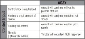
When flying in SAFE Self Leveling/Angle Demand mode, the aircraft will return to level flight any time the aileron and elevator controls are at neutral. Applying aileron or elevator control will cause the airplane to bank, climb or dive. The amount the stick is moved will determine the attitude the airplane flies. Holding full control will push the aircraft to the pre-determined bank and roll limits, but it will not go past those angles.
When flying with Self Leveling/Angle Demand, it is normal to hold the control stick deflected with moderate to full aileron input when flying through a turn. To fly smoothly with Self Leveling/Angle Demand, avoid making frequent control changes and don’t attempt to correct for minor deviations. Holding deliberate control inputs will command the aircraft to fly at a specific angle, and the model will make all corrections to maintain that flight attitude.
When flying with Self Leveling/Angle Demand, you have the option to enable throttle to pitch angle demand. Throttle to pitch will make throttle dictate climb angle. Full throttle will cause the aircraft to pitch up and climb slightly. Mid throttle will keep the airplane flying level. Low throttle will cause the airplane to descend slightly nose-down.
Return the elevator and aileron controls to neutral before switching from Self Leveling/Angle Demand mode to AS3X mode. If you do not neutralize controls when switching into AS3X mode, the control inputs used for Self Leveling/Angle Demand mode will be excessive for AS3X mode and the aircraft will react immediately.
Differences between Self Leveling/Angle Demand and AS3X modesThis section is generally accurate but does not take into account flight speed, battery charge status, and other limiting factors.

Channel Limitations
The AR8360T can use up to seven extra channels for AS3X and SAFE functions; one for Flight Mode selection, one for Panic Mode, and up to five for Gain. You may use any channel up to 20 that is not a control surface or throttle for these functions, and you do not need to use channels 5 and 6, keeping those channels and ports on the receiver open for normal servo operation. However, you may run into channel limitations depending on the number of channels on your transmitter and the number of channels you are using on the receiver.
TIP: If you are experiencing limitations because of channel count, here are a few options;
- You can operate the AR8360T without a channel assigned to Flight Mode, but you will only have access to AS3X options, not SAFE.
- You can set up one self-leveling mode to serve as Panic Mode so you don’t need to dedicate a separate channel for Panic Mode.
- You can operate the AR8360T without a gain channel assigned, and just use fixed gain values throughout the configuration. To do this, first assign flight mode to a channel, then change all gain values to fixed for flight mode 1, then you can unassign the flight mode channel and it will remain in fixed.
Flight Log
Flight Log data can help you optimize the control link for your aircraft. Flight Log data is displayed on telemetry capable Spektrum transmitters.
Using the Flight Log
- A – Fades on main receiver
- B – Fades on remote receiver
- L – Not available on AR8360T
- R – Not available on AR8360T
- F – Frame losses
- H – Holds
FadesRepresents the loss of one bit of information on one receiver. Fades are used to evaluate the performance of each individual receiver. If a fade value is showing higher than the others, inspect or reposition the antenna to optimize the RF link.
Frame LossA frame loss occurs when one complete data packet is missed. A single frame loss does not represent a loss of control, but frame losses should be monitored. In the air it’s normal to experience as many as 100 frame losses per minute of flight. On the ground the number of frame losses will be higher because the signal is hampered by the dirt and moisture.
HoldA hold occurs when 45 consecutive frame losses occur. This takes about one second, and in this event the receiver moves the channel outputs to the failsafe settings. If a hold ever occurs, it’s important to re-evaluate the system and check every component. If your system displays a hold, diagnose the cause and resolve the issue before flying again.
It is normal to see a hold logged if you power OFF your transmitter and back ON.IMPORTANT: The Spektrum Flight Log (SPM9540) is not compatible with the AR8360T receiver.
Range Testing
Before each flying session, and especially with a new model, it’s important to perform a range check. All Spektrum aircraft transmitters incorporate a range testing system, which reduces the output power to allow a range check.
- With the model resting on the ground, stand approximately 100 feet (30 meters) away from the model.
- Face the model with the transmitter in your normal flying position and put your transmitter into range test mode.
- You should have total control of the model in range test mode at 100 feet.
- If you have control issues, review the flight log data to help reposition your antenna(s), and repeat the range test.
- If control issues persist, call Horizon Product Support for further assistance.
Advanced Range TestingThe standard range testing procedure is recommended for most sport aircraft.For sophisticated aircraft that contain significant amounts of conductive materials (e.g. turbine powered jets, scale aircraft with metalized finishes, aircraft with carbon fuselages, etc.), the following advanced range check will confirm that all receivers in the system are operating optimally as installed. This advanced range check allows the RF performance of each receiver to be evaluated independently. A telemetry-equipped Spektrum Transmitter is required for the advanced range test.
- Stand approximately 100 feet away from the model.
- Face the model with the transmitter in your normal flying position and put your transmitter into range test mode.
- Have a helper position the model in various orientations (nose up, nose down, nose toward the transmitter, nose away from the transmitter, etc.).
- Observe the telemetry on your transmitter. Note any orientations that cause higher fades or frame loss values. Perform this step for at least one minute.
- Reposition any remote receivers showing higher fades as necessary.
- Retest to verify satisfactory results.
- Repeat as necessary.
After one minute, advanced testing should yield:H – 0 holdsF – Fewer than 10 frame lossesA, B – Fades will typically be fewer than 100. It’s important to compare the relative fades. If a particular receiver has a significantly higher number of fades (2 to 3X) then the test should be redone. If the same results occur, move the offending receiver to a different location.TIP: Use the fade values for A to investigate the performance of the telemetry link.
Receiver Power System Requirements
Some of the power system components that affect the power supply to the receiver include:
- Receiver battery pack (number of cells, capacity, cell type, state of charge).
- The ESC’s capability to deliver adequate voltage to the receiver when the servos demand high current
- The switch harness, battery leads, servo leads, regulators etc.
The AR8360T has a minimum operational voltage of 3.5 volts; it is highly recommended the power system be tested per the guidelines below.
Recommended Power System Test GuidelinesWe recommend performing the following tests on any new setup to verify power system performance:
- View the receiver voltage during this test on your transmitter’s telemetry screen
- Load the control surfaces (apply pressure with your hand) while monitoring the voltage at the receiver.
- The voltage should remain above 4.8 volts even when all servos are loaded.
How QuickConnect™ Technology Works
- When the receiver voltage drops below 3.5 volts, the system ceases to operate.
- When power is restored, the receiver immediately attempts to reconnect.
- If the transmitter was left on, the system reconnects typically in about 4/100 of a second.
QuickConnect is designed to allow you to fly safely through most short duration power interruptions, however, the root cause of these interruptions must be corrected before the next flight to prevent a crash.
NOTICE: If a brownout occurs in flight it is vital that the cause of the brownout be determined and corrected.
Glossary
AS3X– Stabilization technology that dampens wind and turbulence. Designed to support advanced fliers, AS3X does not include self-leveling technology.
SAFE Envelope– (Intermediate Mode) Stabilization technology that uses AS3X to deliver normal flight performance, but with limited bank and pitch angles to prevent the airplane from getting into extreme attitudes.
SAFE Self Level/Angle Demand– Stabilization technology that will make the airplane return to level flight when the control stick is centered.
Panic Mode– Sometimes called a bailout mode, Panic is a SAFE stabilization mode that can return an airplane to level flight from any attitude. It is usually assigned to a momentary button.
Flight Modes in Receiver– Determine what stabilization modes the aircraft operates in. All the associated stabilization features to tune the flight stabilization can be adjusted per Flight Mode in the receiver (Base Gain, Priority, Heading, etc).
Flight Modes in Transmitter– Manage rates, expo, voice/sound output, and other transmitter based configurations.
Heading- An optional feature of AS3X, heading will make the airplane try to hold its attitude when the control is relaxed. This is not a self-leveling feature, it only makes the aircraft track accurately.
Gain– Tells the stabilization system the level of damping it should provide.
SRXL2– A Bi-Directional data communication protocol that enables digital devices to communicate over a single signal wire.
Forward Programming– Programming directly on the receiver from the transmitter. The receiver has all screens, menus and settings in its internal memory. The receiver is using the telemetry link to the transmitter for the interface, the screen and buttons.
Throttle Cut– Disables throttle function
Oscillation– Sometimes called a wag, this is a back and forth movement similar to a vibration that may appear like a wobble. It may occur around any axis, roll, pitch or yaw. It is most likely to occur on one axis, not all three.
Overshoot– When the stability system makes corrections it is a balancing act, if the response is too strong the system will go past where it should stop, this is called an overshoot.
Angle Limits– Only available in SAFE modes, these values define the limits for the bank and pitch angles.
High Thr to Pitch– This setting defines the angle the airplane will climb at whenthe throttle is raised above half. This is only available in Self Leveling modes.
Low Thr to Pitch– This setting defines the angle the airplane will descend at when the throttle is lowered below half. This is only available in Self Leveling modes.
Brownout– If the receiver power supply drops below 3.5volts, the receiver will not have sufficient power for operation and the resulting loss of control is call a brownout. A brownout results from an inadequate power supply to the receiver, it is a failure outside of the receiver.
Optional Accessories
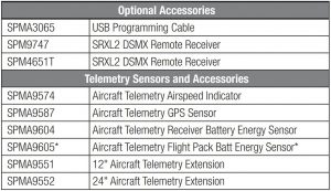
*For use with electric power system batteries that are separate from the receiver battery(s).
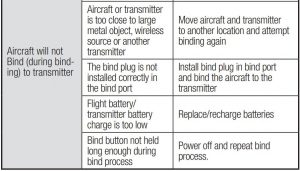
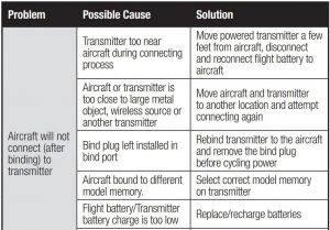
Troubleshooting Guide AS3X
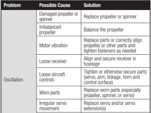
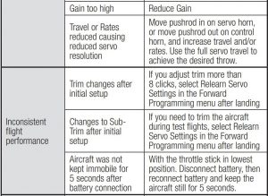

Troubleshooting Guide


1-YEAR LIMITED WARRANTY
What this Warranty Covers – Horizon Hobby, LLC, (Horizon) warrants to the original purchaser that the product purchased (the “Product”) will be free from defects in materials and workmanship for a period of 1 year from the date of purchase.
What is Not Covered – This warranty is not transferable and does not cover (i) cosmetic damage, (ii) damage due to acts of God, accident, misuse, abuse, negligence, commercial use, or due to improper use, installation, operation or maintenance, (iii) modification of or to any part of the Product, (iv) attempted service by anyone other than a Horizon Hobby authorized service center, (v) Product not purchased from an authorized Horizon dealer, (vi) Product not compliant with applicable technical regulations, or (vii) use that violates any applicable laws, rules, or regulations.
OTHER THAN THE EXPRESS WARRANTY ABOVE, HORIZON MAKES NO OTHERWARRANTY OR REPRESENTATION, AND HEREBY DISCLAIMS ANY AND ALLIMPLIED WARRANTIES, INCLUDING, WITHOUT LIMITATION, THE IMPLIEDWARRANTIES OF NON-INFRINGEMENT, MERCHANTABILITY AND FITNESS FORA PARTICULAR PURPOSE. THE PURCHASER ACKNOWLEDGES THAT THEYALONE HAVE DETERMINED THAT THE PRODUCT WILL SUITABLY MEET THEREQUIREMENTS OF THE PURCHASER’S INTENDED USE.
Purchaser’s Remedy – Horizon’s sole obligation and purchaser’s sole and exclusive remedy shall be that Horizon will, at its option, either (i) service, or (ii) replace, any Product determined by Horizon to be defective. Horizon reserves the right to inspect any and all Product(s) involved in a warranty claim. Service or replacement decisions are at the sole discretion of Horizon. Proof of purchase is required for all warranty claims. SERVICE OR REPLACEMENT AS PROVIDED UNDER THIS WARRANTY IS THE PURCHASER’S SOLE AND EXCLUSIVE REMEDY. Limitation of Liability – HORIZON SHALL NOT BE LIABLE FOR SPECIAL, INDIRECT, INCIDENTAL OR CONSEQUENTIAL DAMAGES, LOSS OF PROFITS OR PRODUCTION OR COMMERCIAL LOSS IN ANY WAY, REGARDLESS OF WHETHER SUCH CLAIM IS BASED IN CONTRACT, WARRANTY, TORT, NEGLIGENCE, STRICT LIABILITY OR ANY OTHER THEORY OF LIABILITY, EVEN IF HORIZON HAS BEEN ADVISED OF THE POSSIBILITY OF SUCH DAMAGES. Further, in no event shall the liability of Horizon exceed the individual price of the Product on which liability is asserted. As Horizon has no control over use, setup, final assembly, modification or misuse, no liability shall be assumed nor accepted for any resulting damage or injury. By the act of use, setup or assembly, the user accepts all resulting liability. If you as the purchaser or user are not prepared to accept the liability associated with the use of the Product, purchaser is advised to return the Product immediately in new and unused condition to the place of purchase.
Law – These terms are governed by Illinois law (without regard to conflict of law principals). This warranty gives you specific legal rights, and you may also have other rights which vary from state to state. Horizon reserves the right to change or modify this warranty at any time without notice.
WARRANTY SERVICESQuestions, Assistance, and Services – Your local hobby store and/or place of purchase cannot provide warranty support or service. Once assembly, setup or use of the Product has been started, you must contact your local distributor or Horizon directly. This will enable Horizon to better answer your questions and service you in the event that you may need any assistance. For questions or assistance, please visit our website at www.horizonhobby.com, submit a Product Support Inquiry at https://www.horizonhobby.com/content/service-center-render-service-center or call the toll free telephone number referenced in the Warranty and Service ContactInformation section to speak with a Product Support representative.
Inspection or Services – If this Product needs to be inspected or serviced and is compliant in the country you live and use the Product in, please use the Horizon Online Service Request submission process found on our website or call Horizon to obtain a Return Merchandise Authorization (RMA) number. Pack the Product securely using a shipping carton. Please note that original boxes may be included, but are not designed to withstand the rigors of shipping without additional protection. Ship via a carrier that provides tracking and insurance for lost or damaged parcels, as Horizon is not responsible for merchandise until it arrives and is accepted at our facility. An Online Service Request is available at http://www.horizonhobby.com/content/_service-center_render-service-center. If you do not have internet access, please contact Horizon Product Support to obtain a RMA number along with instructions for submitting your product for service. When calling Horizon, you will be asked to provide your complete name, street address, email address and phone number where you can be reached during business hours. When sending product into Horizon, please include your RMA number, a list of the included items, and a brief summary of the problem. A copy of your original sales receipt must be included for warranty consideration. Be sure your name, address, and RMA number are clearly written on the outside of the shipping carton. Provided warranty conditions have been met, your Product will be serviced or replaced free of charge. Service or replacement decisions are at the sole discretion of Horizon.
NOTICE: Do not ship LiPo batteries to Horizon. If you have any issue with a LiPo battery, please contact the appropriate Horizon Product Support office. Warranty Requirements – For Warranty consideration, you must include your original sales receipt verifying the proof-ofpurchase date.
Non-Warranty Service – Should your service not be covered by warranty, service will be completed and payment will be required without notification or estimate of the expense unless the expense exceeds 50% of the retail purchase cost. By submitting the item for service you are agreeing to payment of the service without notification. Service estimates are available upon request. You must include this request with your item submitted for service. Non-warranty service estimates will be billed a minimum of ½ hour of labor. In addition you will be billed for return freight. Horizon accepts money orders and cashier’s checks, as well as Visa, MasterCard, American Express, and Discover cards. By submitting any item to Horizon for service, you are agreeing to Horizon’s Terms and Conditions found on our websitehttp://www.horizonhobby.com/content/_service-center_render-service-center.
ATTENTION: Horizon service is limited to Product compliant in the country of use and ownership. If received, a non-compliant Product will not be serviced. Further, the sender will be responsible for arranging return shipment of the un-serviced Product, through a carrier of the sender’s choice and at the sender’s expense. Horizon will hold noncompliant Product for a period of 60 days from notification, after which it will be discarded.
Warranty and Service Contact Information

FCC Information
FCC ID: BRWSPMAR8360TSupplier’s Declaration of ConformityAR8360T 8CH Telemetry Receiver (SPMAR8360T)
![]() This device complies with part 15 of the FCC Rules. Operation is subject to the following two conditions: (1) This device may not cause harmful interference, and (2) this device must accept any interference received, including interference that may cause undesired operation.
This device complies with part 15 of the FCC Rules. Operation is subject to the following two conditions: (1) This device may not cause harmful interference, and (2) this device must accept any interference received, including interference that may cause undesired operation.
CAUTION: Changes or modifications not expressly approved by the party responsible for compliance could void the user’s authority to operate the equipment.
NOTE: This equipment has been tested and found to comply with the limits for a Class B digital device, pursuant to part 15 of the FCC Rules. These limits are designed to provide reasonable protection against harmful interference in a residential installation.
This equipment generates, uses and can radiate radio frequency energy and, if not installed and used in accordance with the instructions, may cause harmful interference to radio communications.
However, there is no guarantee that interference will not occur in a particular installation. If this equipment does cause harmful interference to radio or television reception, which can be determined by turning the equipment off and on, the user is encouraged to try to correct the interference by one or more of the following measures:
- Reorient or relocate the receiving antenna.
- Increase the separation between the equipment and receiver.
- Connect the equipment into an outlet on a circuit different from that to which the receiver is connected.
- Consult the dealer or an experienced radio/TV technician for help.
Horizon Hobby, LLC2904 Research Rd.,Champaign, IL 61822Email: Web: HorizonHobby.com
IC Information
CAN ICES-3 (B)/NMB-3(B)IC: 6157A-SPMAR8360TThis device contains license-exempt transmitter(s)/receivers(s) that comply with Innovation, Science, and Economic Development Canada’s license-exempt RSS(s). Operation is subject to the following 2 conditions:
- This device may not cause interference.
- This device must accept any interference, including interference that may cause undesired operation of the device.
Compliance Information for the European Union
 EU Compliance Statement:AR8360T 8CH Telemetry Receiver (SPMAR8360T); Hereby, Horizon Hobby, LLC declares that the device is in compliance with the following: EU Radio Equipment Directive 2014/53/EU; RoHS 2 Directive 2011/65/EU; RoHS 3 Directive – Amending 2011/65/EU Annex II 2015/863.
The full text of the EU declaration of conformity is available at the following internet address: https://www.horizonhobby.com/content/support-rendercompliance.
Wireless Frequency Range and Wireless Output Power:Frequency Band: 2404 – 2476 MHzMax EIRP: 19.42dBm
EU Manufacturer of Record:Horizon Hobby, LLC2904 Research RoadChampaign, IL 61822 USA
EU Importer of Record:Horizon Hobby, GmbHHanskampring 922885 Barsbüttel Germany
WEEE NOTICE:
![]() This appliance is labeled in accordance with European Directive 2012/19/EU concerning waste of electrical and electronic equipment (WEEE). This label indicates that this product should not be disposed of with household waste. It should be deposited at an appropriate facility to enable recovery and recycling.
This appliance is labeled in accordance with European Directive 2012/19/EU concerning waste of electrical and electronic equipment (WEEE). This label indicates that this product should not be disposed of with household waste. It should be deposited at an appropriate facility to enable recovery and recycling.
![]()
© 2021 Horizon Hobby, LLC.DSM, DSM2, DSMX, SAFE, AS3X, Spektrum Airware, SRXL2, SmartSafe, Avian, and the Horizon Hobby logo are trademarks or registered trademarks of Horizon Hobby, LLC.The Spektrum trademark is used with permission of Bachmann Industries, Inc.US 7,391,320. US 9,056,667. US 9,753,457. US 9,930,567. US 10,078,329. US 10,419,970. US 10,849,013.
References
Horizon Hobby Service Center
RC Airplanes and Helicopters, RC Cars and Trucks, RC Boats, RC Radios | Horizon Hobby
RC Cars, RC Trucks, RC Airplanes, Model Trains, and Slot Cars at Tower Hobbies
RC Airplanes and Helicopters, RC Cars and Trucks, RC Boats, RC Radios | Horizon Hobby
Spektrum RC Transmitters and RC Electronics | Spektrum
RC Airplanes and Helicopters, RC Cars and Trucks, RC Boats, RC Radios | Horizon Hobby
Product Serivce Center
RC Airplanes and Helicopters, RC Cars and Trucks, RC Boats, RC Radios | Horizon Hobby
[xyz-ips snippet=”download-snippet”]