SPEKTRUm SPMXSEMC08 Sensored 1/10th Scale Crawler ESC Instruction Manual
NOTICE
All instructions, warranties and other collateral documents are subject to change at the sole discretion of Horizon Hobby, LLC. For up-todate product literature, visit horizonhobby.com or towerhobbies.com and click on the support or resources tab for this product.
Meaning of Special Language
The following terms are used throughout the product literature to indicate various levels of potential harm when operating this product:
WARNING: Procedures, which if not properly followed, create the probability of property damage, collateral damage, and serious injury OR create a high probability of superficial injury.
CAUTION: Procedures, which if not properly followed, create the probability of physical property damage AND a possibility of serious injury.
NOTICE: Procedures, which if not properly followed, create a possibility of physical property damage AND a little or no possibility of injury.
WARNING: Read the ENTIRE instruction manual to become familiar with the features of the product before operating. Failure to operate the product correctly can result in damage to the product, personal property and cause serious injury.
This is a sophisticated hobby product. It must be operated with caution and common sense and requires some basic mechanical ability.Failure to operate this Product in a safe and responsible manner could result in injury or damage to the product or other property. This product is not intended for use by children without direct adult supervision. Do not attempt disassembly, use with incompatible components or augment product in any way without the approval of Horizon Hobby, LLC. This manual contains instructions for safety, operation and maintenance. It is essential to read and follow all the instructions and warnings in the manual, prior to assembly, setup or use, in order to operate correctly and avoid damage or serious injury.
Age Recommendation: Not for children under 14 years. This is not a toy.
NOTICE: This product is only intended for use with unmanned, hobby-grade, remote-controlled vehicles and aircraft. Horizon Hobby disclaims all liability outside of the intended purpose and will not provide warranty service related thereto.
ESC Specifications SPMXSE1060
- Cont./Peak Current: 60A/360A
- Motor Type: Only Spektrum Sensorless Motors
- Compatible Motors: SPMXSM3000, SPMXSM3001, SPMXSM3002,
- Applications: 1/10th Rock Crawler
- LiPo/NiMH Cells: 2-3S LiPo, 6-9S NiMH
- BEC Output: 6V/7.4V Switchable, Continuous Current of 3A (Switch-mode)
- Motor Connectors: 4mm Bullet
- Dimensions: 47.4mm x 36.2mm x 24.6mm
- Weight: 82g
- Programming: SPMXCA200 Programmer Box Required
Gearing
Improper gearing will cause excessive heat buildup in the motor and speed control. Use your vehicle’s kit manual in order to find the manufacturer’s recommended pinion size. It is best to monitor the system’s operating temperature when you are operating on new and different tracks or racing surfaces. Your system’s operating temperature should never exceed 160° F (71° C). The best place to monitor the system’s temperature is at the center of the end bell. If the temperature is higher than 160° F (71° C) after a 5 minute run, the gearing should be lowered (change to a smaller pinion gear).
CAUTION: Once the battery is connected to the system, stay clear of the rotating shaft and pinion gear. Failure to do so could result in personal injury.
Installation of the System
Always ensure the mounting screws are long enough to properly seat into the motor. However, ensure the screws do not enter into the motor too far, which could cause damage.The maximum depth that the mounting screws can enter into the motor is approximately 3/16 in (5mm). We suggest using the mounting hardware included with your vehicle. The use of screws that are too long will damage the system and void any warranty.When installing the motor into your vehicle, it is very important that the gear mesh is correct and smooth with no binding. The vehicle’s motor mounts usually feature adjustable slotted mounting holes so that you can adjust the gear mesh properly.
Proper gear mesh (how gear teeth meet) is important to the performance of the vehicle. When the gear mesh is too loose, the spur gear could be damaged by the pinion gear of the motor. If the mesh is too tight, speed could be limited and the system will overheat. Insert a small piece of paper in between the pinion and spur gears as you are installing them. Push the gears together while tightening the screws that mount the system. When the mesh is at the correct distance, remove the small piece of paper by rotating the spur gear until the paper comes out. Check the mesh at multiple points around the larger spur gear before finalizing the motor mounting position.
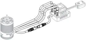
Connecting the Motor to the ESC
- The Firma 60a Sensored brushless ESC only supports the Spektrum Sensorless brushless motors. This ESC cannot be paired with any other type of motor. These Spektrum Motors cannot be used with any other type of ESC.
- There is strict wiring order from the ESC to the motor. The threeA/B/C ESC connections must connect to the three A/B/C motor wires correspondingly.Connect ESC Terminal A to Motor Terminal A; ESC Terminal B to Motor Terminal B; and ESC Terminal C to Motor Terminal C. Unlike sensorless ESCs and motors, you cannot change the wiring order with a sensored ESC and motor. Never change the order of your motor wires or damage will occur.
- Connect the ESC sensor wire to the motor sensor wire.

NOTICE: Always disconnect the battery from the system when you have finished operating your vehicle. The system’s switch only controls power to the receiver and servos. The system will continue to draw current when connected to the battery, resulting in possible damage to the battery through over-discharge.
Automatic Motor Pairing
When you first connect a motor, if you change to a different Kv motor, or if the motor has been subjected to severe impact or has abnormal heating and abnormal power output during operation, you will need follow these instructions for automatic motor pairing.
- Disconnect the throttle cable from the receiver, and remove the motor pinion.
- Connect the battery, press and hold the power button. The switch for the ESC will flash red, then a short double flash that repeats after about seconds, then you can release the power button.
- It will enter the automatic motor pairing process and the motor will automatically rotate (the greed light inside the ESC will flash at the same time).
- When the motor stops, the green led will turn on solid.
- After the automatic motor pairing is completed, the ESC will self-check (power-on tones). Reconnect the throttle line and restart/repower the ESC to operate normally.
IMPORTANT: Remove the motor pinion before performing the automatic motor pairing, if the drivetrain is connected it will prevent proper operation.
Throttle Signal
Smart Throttle:The Spektrum Firma™ ESC is compatible with Smart Throttle. Smart Throttle combines throttle signals with telemetry data from the ESC on one normal three wire servo connector. Smart Throttle compatible receivers will detect a Smart Throttle ESC and automatically begin to send telemetry information to your transmitter.
Using the Smart Throttle connection this ESC can send voltage, current, and other telemetry data. It can also pass along battery data from compatible Spektrum Smart batteries. A Spektrum Smart battery with IC3™ or IC5™ connector is required for battery data. EC3™ connectors are compatible for basic operation, but will not provide Smart battery data.
Only certain Spektrum telemetry receivers include Smart Throttle, check your receiver manual for more information. If the ESC is not connected to a SmartThrottle compatible receiver no telemetry data from the ESC will be available, but the ESC will operate normally with a common servo signal (PWM).Normal Servo Signal (PWM):
The Firma ESCs are fully compatible with common RC receivers and will use a conventional PWM signal for basic operation.
NOTICE: Do not connect a dedicated receiver battery to the receiver along with the ESC. When the ESC is turned On it will provide the receiver with 6V regulated power from the main battery through the throttle connection. The ESC may be damaged if the receiver is also connected to a dedicated receiver battery.
ESC Calibration
In order to make the ESC match the throttle range, you must calibrate it when you begin to use a new ESC. If you install a new radio system, or make changesto your throttle/brake values in your transmitter, you must redo the ESC Calibration Process. Failure to calibrate the ESC to your radio system will result in the ESC not working correctly. Set the Fail Safe on your radio to a neutral position to ensure the motor stops in the event of a signal loss.
- Power ON your transmitter, and begin with throttle values at 100% for dual rates and travel, and at neutral for trim and sub-trim. Verify there are no ABS braking functions activated before proceeding with calibration.For transmitters without an LCD, turn the D/R knob to the max setting, and center the throttle trim.
- Connect a battery to the ESC.
- Press and hold the power button. The red LED on the ESC will start to flash and the motor will beep, release the power button (The ESC will enter theprogramming mode if the SET button is not released within 8 seconds)
- With the throttle trigger and trim in the neutral position, press and release the power button. The Green LED will flash once and the motor will emit one tone.
- Pull the throttle trigger to full throttle, and press and release the power button. The Green LED will flash twice and the motor will emit two tones.
- Push the throttle trigger to full reverse, and press and release the SET button. The Green LED will flash three times and the motor will emit three tones.
- When calibration is complete the motor will operate normally.
Operation
- Power ON your transmitter.
- Connect a battery to the ESC.
- Press and release the ON/OFF button to Power ON the vehicle
- After operation, press and release the ON/OFF button to power OFF the vehicle, or unplug the battery.
IMPORTANT: Always unplug the battery after operation. If you leave the battery connected for an extended period of time, it will slowly drain the battery to zero volts and cause permanent damage to your battery.
Programming Options
| Item | Programmable Item | Option 1 | Option 2 | Option 3 | Option 4 | Option 5 | Option 6 | Option 7 | Option 8 | Option 9 | Option 10 |
| 1 | Cutoff Voltage | Disabled | 3.0V/Cell | 3.2V/Cell | 3.4V/Cell | ||||||
| 2 | Max. Forward Force | 25% | 37.5% | 50% | 62.5% | 75% | 87.5% | 100% | |||
| 3 | Max. Reverse Force | 25% | 37.5 | 50% | 62.5% | 75% | 87.5% | 100% | |||
| 4 | Turbo Timing | 0° – 10° Adjustable in 1° Increments (0° Default) | |||||||||
| 5 | Turbo Delay | Instant | 0.1s | 0.2s | 0.3s | 0.4s | 0.5s | ||||
| 6 | Drag Brake Force | 50% – 200% Adjustable in 5% Increments (Default: 80%) | |||||||||
| 7 | Drag Brake Rate | Level 1 | Level 2 | Level 3 | Level 4 | Level 5 | Level 6 | Level 7 | Level 8 | Level 9 | Auto |
| 8 | Neutral Range | 6% –17% Adjustable in 1% Increments (Default: 10%) | |||||||||
| 9 | Start Mode (/ Punch) | Level 1 | Level 2 | Level 3 | Level 4 | Level 5 | Level 6 | Level 7 | Level 8 | Level 9 | |
| 10 | BEC Voltage | 6.0V | 7.4V | ||||||||
| 11 | Motor Rotation | CW | CCW |
- Cutoff VoltageLow Voltage Cutoff (LVC) for Lipo Protection. This item is mainly for preventing LiPo packs from being over-discharged. If the LVC is enabled, the ESC will reduce the output to 50% and cut power 10 seconds later when the voltage goes below the cutoff threshold. The red LED will begin a repeating single flash when the ESC enters LVC.If the LVC is disabled, the ESC will not cut off the power when the voltage is low. We don’t recommend setting the LVC to “Disabled” when using a LiPo pack, Without LVC it is easy for a LiPo battery to be damaged due to over-discharge.
- NIMH – For a NiMH pack, we recommend setting this item to “Disabled.”
- Cutoff Voltage – The ESC will set the cutoff for the pack based on the voltage the battery is at when the battery is connected.
- Max. Forward ForceThe power applied to the motor when the throttle trigger is at the full throttle position. You can reduce the value for better driving feel/control when you drive a crawler over difficult terrain.
- Max. Reverse ForceThe power applied to the motor when the throttle trigger is at the full reverse position. We recommend using a low value for most drivers.
- Turbo TimingThis item is adjustable from 0 degree to 10 degrees, the value you select will initiate at full throttle. It’s usually activated on long straightaways and makes the motor unleash its maximum potential. Turbo timing adds a margin of power at full throttle.
- Turbo DelayWhen “Turbo Delay” is set to “Instant”, the Turbo Timing will be activated immediately when the throttle trigger is moved to the full throttle position. Turbo Delay values will delay the application of the selected Turbo Timing value.
- Drag Brake ForceBraking power when the throttle is at the neutral position. Higher drag brake values are used to provide a stronger hold or hill brakes.IMPORTANT: Drag brakes will consume more power and heat will be increased, start with small values and use with caution. Improve ventilation to ESC if heat is excessive.
- Drag Brake RateThis feature manages how rapidly the ESC applies drag brakes. Choose the drag brake rate from level 1 (very soft) to level 9 (very aggressive); lower values ramp the brakes slower and prevent sudden stops or jerky stopping movements.In Auto mode, the ESC adjusts the Drag Brake Rate automatically based on the current speed and can be helpful to prevent the vehicle from flipping over or from sustaining drivetrain damage from harsh braking, but also provides a sensitive braking feel at low speeds;
- The higher the current speed, the lower the drag brake rate.
- The lower the current speed, the higher the drag brake rate.
- Neutral RangeAdjust this parameter to your preference to account for deadband in the throttle response. If you notice inconsistent drag brakes, increase your Neutral Range value.
- Start Mode/(Punch)Set the punch from level 1 (very soft) to level 9 (very aggressive). This feature is very useful for preventing tires from spinning. Punch levels 7 and above require high discharge capable batteries. If the car stutters or suddenly loses power when accelerating it may indicate the battery does not have adequate discharge capabilities for the application. Reduce the punch value, pinion gear size, or change to a higher C rated battery.
- BEC Voltage
- Option 1: 6.0V Appropriate for most standard servos. Not recommended for High Voltage (HV) servos.
- Option 2: 7.4V Appropriate for high voltage servos. Do not use this option with standard servos; it’s possible a standard 5 – 6 Volt rated servo will be damaged at this voltage setting.
Programming with the SPMXCA200 Smart Programmer Box
- Connect the programming box to the switch.
- Connect a battery to the ESC.
- Power on the box and select the parameter with the SELECT button.
- Change the values of the selected parameter with the EDIT button
- Press the SAVE button to save the changes. The ESC requires a power cycle to implement the saved changes.
Factory Reset
It is possible to restore the default values if necessary.
- After connecting the ESC to the programming card, press “RESET” key and then press “SAVE” key to save, the factory settings can be restored.After applying a factory reset, you must perform the calibration procedure before operating your vehicle.
Status LEDs
- During the start up process;
- The red LED keeps flashing rapidly indicating the ESC doesn’t detect any throttle signal, or the neutral throttle value stored on your ESC may be different from the current value stored on the transmitter. Redo the ESC calibration process if your ESC is flashing and not working.
- The green LED flashes a number of times, indicating the number of LiPo cells you have plugged in.
- In Operation – What lights you should see.
- The red & green LEDs go out when the throttle trigger is in throttle neutral zone.
- The red LED illuminates when your vehicle runs forward. The green LED will also illuminate when pulling the throttle trigger to the full (100%) throttle endpoint and setting the “Max. Forward Force” to 100%.
- The red LED illuminates when you brake the vehicle, the green LED will also illuminate when pushing the throttle trigger to the full brake endpoint and setting the “Max. Reverse Force” to 100%.
- Error or Warning LED codes
- The red LED flashes a short, repeating single flash, indicating the low voltage cutoff protection is activated.
- The green LED flashes a short, repeating single flash, indicating the ESC thermal protection is activated.
- The green LED flashes a short, repeating double flash, indicating the motor thermal protection is activated.
- The green and red LEDs flash a short, repeating double flash, indicating the power system stops functioning due to “sensor issue”. In that case, please check if the ESC sensor wire has been firmly connected to the motor sensor wire before resuming the operation.
| Problem | Possible Cause | Possible Solution |
| The ESC is not starting, and no status LED is lit. |
|
|
| The ESC was unable to start the motor, sounded a continuous repeating tone with a one second interval, and the green LED on the ESC flashed. | The battery voltage is beyond the normal range. | Check if the battery voltage is within the specified range. |
| After the ESC is powered on and finished LiPo detection,the green LED flashed X number of times, and then the red LED flashed. |
|
the throttle trigger to the neutral position. |
| The vehicle runs backward when you pull the throttle trigger for forward. | The default motor direction doesn’t match your chassis. | Reverse the motor using the SPMXCA200 programmer box |
| The motor suddenly stopped or significantly reduced the output in operation. |
|
|
| The vehicle won’t start operation, and the red and green LEDs flash a short, repeating double flash. |
|
|
| The throttle response is bad close to neutral and the vehicle wants to crawl. |
|
|
| When pressing the SET button to set the throttle neutral position, the green LED didn’t flash and no beep was emitted, or you were unable to set the full throttle endpoint and the full brake endpoint after the neutral position was accepted. |
|
|
1-Year Limited Warranty
What this Warranty CoversHorizon Hobby, LLC, (Horizon) warrants to the original purchaser that the product purchased (the “Product”) will be free from defects in materials and workmanship for a period of 1 year from the date of purchase.
What is Not CoveredThis warranty is not transferable and does not cover (i) cosmetic damage, (ii) damage due to acts of God, accident, misuse, abuse, negligence, commercial use, or due to improper use, installation, operation or maintenance, (iii) modification of or to any part of the Product, (iv) attempted service by anyone other than a Horizon Hobby authorized service center, (v) Product not purchased from an authorized Horizon dealer, (vi) Product not compliant with applicable technical regulations, or (vii) use that violates any applicable laws, rules, or regulations. OTHER THAN THE EXPRESS WARRANTY ABOVE, HORIZON MAKES NO OTHER WARRANTY OR REPRESENTATION, AND HEREBY DISCLAIMS ANY AND ALL IMPLIED WARRANTIES, INCLUDING, WITHOUT LIMITATION, THE IMPLIED WARRANTIES OF NON-INFRINGEMENT, MERCHANTABILITY AND FITNESS FOR A PARTICULAR PURPOSE. THE PURCHASER ACKNOWLEDGES THAT THEY ALONE HAVE DETERMINED THAT THE PRODUCT WILL SUITABLY MEET THE REQUIREMENTS OF THE PURCHASER’S INTENDED USE.
Purchaser’s RemedyHorizon’s sole obligation and purchaser’s sole and exclusive remedy shall be that Horizon will, at its option, either (i) service, or (ii) replace, any Product determined by Horizon to be defective. Horizon reserves the right to inspect any and all Product(s) involved in a warranty claim. Service or replacement decisions are at the sole discretion of Horizon. Proof of purchase is required for all warranty claims. SERVICE OR REPLACEMENT AS PROVIDED UNDER THIS WARRANTY IS THE PURCHASER’S SOLE AND EXCLUSIVE REMEDY.
Limitation of LiabilityHORIZON SHALL NOT BE LIABLE FOR SPECIAL, INDIRECT, INCIDENTAL OR CONSEQUENTIAL DAMAGES, LOSS OF PROFITS OR PRODUCTION OR COMMERCIAL LOSS IN ANY WAY, REGARDLESS OF WHETHER SUCH CLAIM IS BASED IN CONTRACT, WARRANTY, TORT, NEGLIGENCE, STRICT LIABILITY OR ANY OTHER THEORY OF LIABILITY, EVEN IF HORIZON HAS BEEN ADVISED OF THE POSSIBILITY OF SUCH DAMAGES. Further, in no event shall the liability of Horizon exceed the individual price of the Product on which liability is asserted. As Horizon has no control over use, setup, final assembly, modification or misuse, no liability shall be assumed nor accepted for any resulting damage or injury. By the act of use, setup or assembly, the user accepts all resulting liability. If you asthe purchaser or user are not prepared to accept the liability associated with the use of the Product, purchaser is advised to return the Product immediately in new and unused condition to the place of purchase.
LawThese terms are governed by Illinois law (without regard to conflict of law principals). This warranty gives you specific legal rights, and you may also have other rights which vary from state to state. Horizon reserves the right to change or modify this warranty at any time without notice.
WARRANTY SERVICES
Questions, Assistance, and ServicesYour local hobby store and/or place of purchase cannot provide warranty support or service. Once assembly, setup or use of the Product has been started, you must contact your local distributor or Horizon directly. This will enable Horizon to better answer your questions and service you in the event that you may need any assistance. For questions or assistance, please visit our website at www.horizonhobby.com, submit a Product Support Inquiry, or call the toll free telephone number referenced in the Warranty and Service Contact Information section to speak with a Product Support representative.
Inspection or ServicesIf this Product needs to be inspected or serviced and is compliant in the country you live and use the Product in, please use the Horizon Online Service Request submission process found on our website or call Horizon to obtain a Return Merchandise Authorization (RMA) number. Pack the Product securely using a shipping carton. Please note that original boxes may be included, but are not designed to withstand the rigors of shipping without additional protection. Ship via a carrier that provides tracking and insurance for lost or damaged parcels, as Horizon is not responsible for merchandise until it arrives and is accepted at our facility. An Online Service Request is available at http://www.horizonhobby.com/content/ service-center_render-service-center. If you do not have internet access, please contact Horizon Product Support to obtain a RMA number along with instructions for submitting your product for service. When calling Horizon, you will be asked to provide your complete name, street address, email address and phone number where you can be reached during business hours. When sending product into Horizon, please include your RMA number, a list of the included items, and a brief summary of the problem. A copy of your original sales receipt must be included for warranty consideration. Be sure your name, address, and RMA number are clearly written on the outside of the shipping carton.
NOTICE: Do not ship LiPo batteries to Horizon. If you have any issue with a LiPo battery, please contact the appropriate Horizon Product Support office.
Warranty Requirements
For Warranty consideration, you must include your original sales receipt verifying the proof-of-purchase date. Provided warranty conditions have been met, your Product will be serviced or replaced free of charge. Service or replacement decisions are at the sole discretion of Horizon.
Non-Warranty ServiceShould your service not be covered by warranty, service will be completed and payment will be required without notification or estimate of the expense unless the expense exceeds 50% of the retail purchase cost. By submitting the item for service you are agreeing to payment of the service without notification. Service estimates are available upon request. You must include this request with your item submitted for service. Non-warranty service estimates will be billed a minimum of ½ hour of labor. In addition you will be billed for return freight. Horizon accepts money orders and cashier’s checks, as well as Visa, MasterCard, American Express, and Discover cards. By submitting any item to Horizon for service, you are agreeing to Horizon’s Terms and Conditions found on our website http://www.horizonhobby.com/content/service-center_render-service-center
ATTENTION: Horizon service is limited to Product compliant in the country of use and ownership. If received, a non compliant Product will not be serviced. Further, the sender will be responsible for arranging return shipment of the unserviced Product, through a carrier of the sender’s choice and at the sender’s expense. Horizon will hold non-compliant Product for a period of 60 days from notification, after which it will be discarded.
Warranty and Service Contact Information
| Country of Purchase | Horizon Hobby | Contact Information | Address |
| United States of America | Horizon Service Center (Repairs and Repair Requests) | servicecenter.horizonhobby.com/RequestForm/ | 2904 Research Rd. Champaign, Illinois 61822 USA |
| Horizon Product Support (Product Technical Assistance) | [email protected] | ||
| 877-504-0233 | |||
| Sales | [email protected] | ||
| 800-338-4639 |
FCC Information
Supplier’s Declaration of Conformity
Sensored 1/10th Scale Crawler Smart ESC (SPMXSE1060) This device complies with part 15 of the FCC Rules. Operation is subject to the following two conditions: (1) This device may not cause harmful interference, and (2) this device must accept any interference received, including interference that may cause undesired operation.
CAUTION: Changes or modifications not expressly approved by the party responsible for compliance could void the user’s authority to operate the equipment.
NOTE: This equipment has been tested and found to comply with the limits for a Class B digital device, pursuant to part 15 of the FCC Rules. These limits are designed to provide reasonable protection against harmful interference in a residential installation. This equipment generates, uses and can radiate radio frequency energy and, if not installed and used in accordance with the instructions, may cause harmful interference to radio communications. However, there is no guarantee that interference will not occur in a particular installation. If this equipment does cause harmful interference to radio or television reception, which can be determined by turning the equipment off and on, the user is encouraged to try to correct the interference by one or more of the following measures:
- Reorient or relocate the receiving antenna.
- Increase the separation between the equipment and receiver.
- Connect the equipment into an outlet on a circuit different from that to which the receiver is connected.
- Consult the dealer or an experienced radio/TV technician for help.
Horizon Hobby, LLC2904 Research Rd.,Champaign, IL 61822Email: [email protected]Web: HorizonHobby.com
IC Information
CAN ICES-3 (B)/NMB-3(B)
Compliance Information for the European Union
![]() EU Compliance Statement:Sensored 1/10th Scale Crawler Smart ESC (SPMXSE1060); Hereby, Horizon Hobby, LLC declares that the device is in compliance with the following:
EU Compliance Statement:Sensored 1/10th Scale Crawler Smart ESC (SPMXSE1060); Hereby, Horizon Hobby, LLC declares that the device is in compliance with the following:
2014/30/EU EMC Directive;RoHS 2 Directive 2011/65/EU;RoHS 3 Directive – Amending 2011/65/EU Annex II 2015/863..The full text of the EU declaration of conformity is available at the following internet address: https://www.horizonhobby.com/content/support-render-compliance.
EU Manufacturer of Record:Horizon Hobby, LLC2904 Research RoadChampaign, IL 61822 USA
EU Importer of Record:Horizon Hobby, GmbHHanskampring 922885 Barsbüttel Germany
WEEE NOTICE:
![]() This appliance is labeled in accordance with European Directive 2012/19/EU concerning waste of electrical and electronic equipment (WEEE). This label indicates that this product should not be disposed of with household waste.It should be deposited at an appropriate facility to enable recovery and recycling.
This appliance is labeled in accordance with European Directive 2012/19/EU concerning waste of electrical and electronic equipment (WEEE). This label indicates that this product should not be disposed of with household waste.It should be deposited at an appropriate facility to enable recovery and recycling.
References
RC Airplanes and Helicopters, RC Cars and Trucks, RC Boats, RC Radios | Horizon Hobby
RC Cars, RC Trucks, RC Airplanes, Model Trains, and Slot Cars at Tower Hobbies
RC Airplanes and Helicopters, RC Cars and Trucks, RC Boats, RC Radios | Horizon Hobby
Product Service Center – Request Form
Ferngesteuerte Flugmodelle, Autos, Trucks, Hubschrauber, Boote und Fernsteuerungen | Horizon Hobby
RC Airplanes and Helicopters, RC Cars and Trucks, RC Boats, RC Radios | Horizon Hobby
RC Airplanes and Helicopters, RC Cars and Trucks, RC Boats, RC Radios | Horizon Hobby
RC Airplanes and Helicopters, RC Cars and Trucks, RC Boats, RC Radios | Horizon Hobby
RC Airplanes and Helicopters, RC Cars and Trucks, RC Boats, RC Radios | Horizon Hobby
RC Cars, RC Trucks, RC Airplanes, Model Trains, and Slot Cars at Tower Hobbies
[xyz-ips snippet=”download-snippet”]