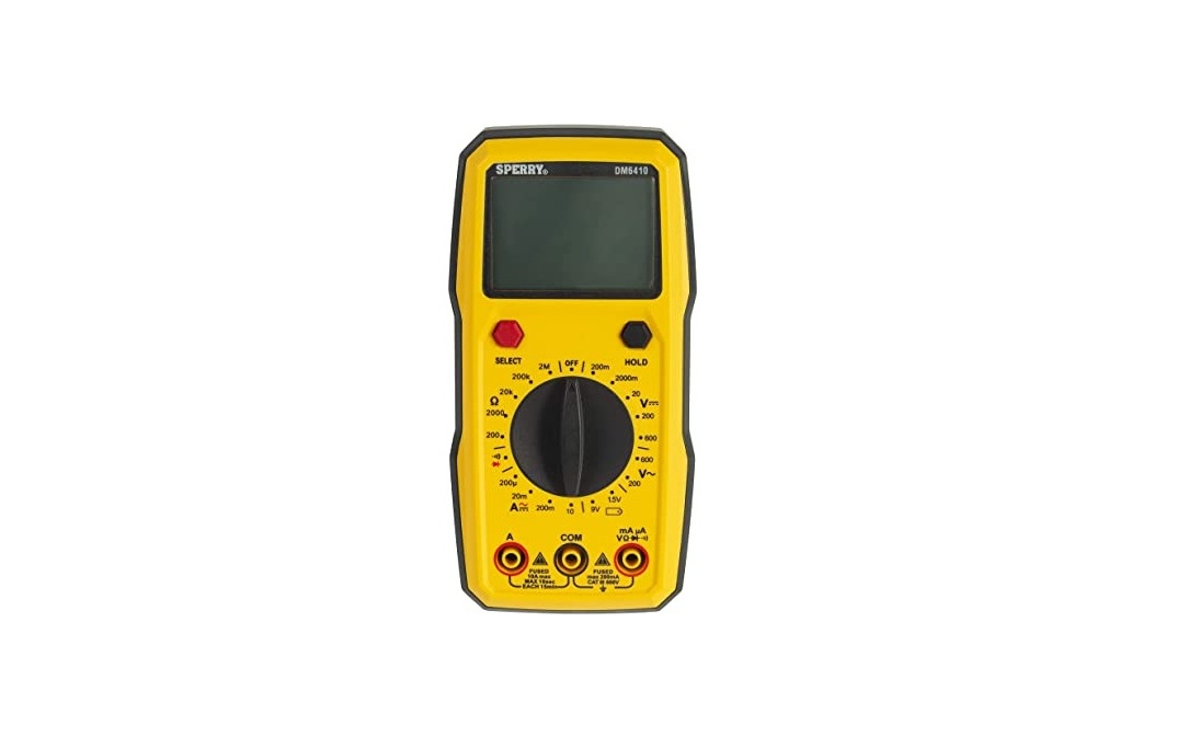
SPERRY INSTRUMENTS 8 Function Digital Autoranging Multimeter DM6410 Instruction Manual
 DM6410
IMPORTANT: RECEIVING INSTRUCTIONS Visually inspect all components for shipping damage. If you find damage, notify the carrier at once. Shipping damage is NOT covered by warranty. The carrier is responsible for all repair or replacement costs resulting from damage in shipment. Read this owners manual thoroughly before use and save. Figure 1
| OFF | Power off |
|
Battery Measurement |
| |
DC Voltage Measurement |  |
AC/DC Current |
 |
AC Voltage Measurement |  |
Continuity / Diode Measurement |
|
Resistance Measurement |
- DISPLAY FUNCTIONS & SYMBOL
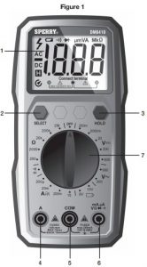
- FUNCTIONS (Figure 1)
- Display: 2000 Count LCD screen
- SELECT Button: Press to switch between AC current and DC current measurement functions and continuity and diode measurement functions.
- HOLD Button: Press to enter or exit the Data Hold mode.
- 10A Terminal: Red test lead input jack for 10A current measurements.
- COM Terminal: Black test lead input jack common to all measurements.
- INPUT Terminal: Red test lead input jack for all measurements expect 10A current measurements.
- Rotary Switch: Turn to power the meter on and off and select the desired measurement function. To save battery power, turn to the “OFF” position when the meter is not in use. See “ROTARY SWITCH” section for function descriptions.
- FUNCTIONS (Figure 1)
METER FUNCTIONS
| Meter type | Auto
|
| Display Count | 200 |
| Battery | Requires 2 AAA batteries |
| Input impedance | 10 Meg 0hm |
| AC Volt Ranges | 200 ,600v,best accuracy (0.8%+5) |
| DC Volt Ranges | 200mv, 200mv,20v and 600v best accuracy(0.5%+5) |
| AC Amps | 200Ua,20Ma,10A,best accuracy(1.0%+3) |
| DC Amps | 200uA,20mA,200mA10A,best accuracy(0.8%+3) |
| Resistance Ranges | 200ohm,200ohm,20kohm,200kohm,2m ohm,best accuracy(0.8+3) |
| Over Range Indication | Displayed value> 1999 or the input measurement range, displays OL |
| Polarity Indication | “-“ is displayed for negative polarity |
| Agency Approvals | ELT CE(IEC/EN61010:,CAT111600V,Pollution Degree 2 |
| Operating Temperature | 32 F- 104 F(-10-50 C) |
| Relative Humidity | <95% |
| Storage Temperature | -4 F-140 F(-10-50 C) |
| IP Degree | Ip20 |
| Dimension | 156mm x 78mm x 28mm |
| Weight | Around 172g(without batteries) |
| Altitude | Maximum 2000m |
| Warranty Info | Limited lifetime warranty |
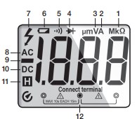
3 DISPLAY SYMBOLS (Figure 2)
- (M)(k)
 : Resistance Measurement
 - (u)(m)A: Current Measurement
- (m)V: Voltage Measurement
- : Diode measurement
- : Continuity Measurement
- : The battery is low and must be replaced
- : The measuring voltage exceeds 30V AC/DC
- AC: AC
- : Negative sign
- DC: D
- Data hold is enabled
- Test lead input icone
2.0 READ FIRST: IMPORTANT SAFETY INFORMATION
Read this operators manual thoroughly before using this multimeter. This manual is intended to provide basic information regarding this meter and to describe common test procedures which can be made with this unit. Many types of appliance, machinery and other electrical circuit measurements are not addressed in this manual and should be handled by experienced service technicians. Use extreme caution when using this multimeter. Improper use of this meter can result in severe damage, personal injury or death. Follow all instructions and suggestions in this operators manual as well as observing normal electrical safety precautions. Do not use this meter if you are unfamiliar with electrical circuits and proper test procedures.2.1 SAFETY WARNINGS ·
- This instruction manual contains warnings and safety rules which must be observed by the user to ensure safe operation of the instrument and retain it in safe condition.
- Read through and understand the instructions contained in this manual before using the instrument.
- Keep the manual at hand to enable quick reference whenever necessary.
- The instrument is to be used only in its intended applications.
- Understand and follow all the safety instructions contained in the manual.
- It is essential that all safety instructions are adhered to.
- Failure to follow the safety instructions may cause injury, instrument damage The symbol indicated on the instrument means that the user must refer to the related parts in the manual for safe operation of the instrument. It is essential to read the instructions wherever the symbol appears in the manual.DANGER is reserved for conditions and actions that are likely to cause serious or fatal injury.WARNING is reserved for conditions and actions that can cause serious or fatal injury.CAUTION is reserved for conditions and actions that can cause injury or instrument damage.DANGER
- Never make measurement on a circuit in which voltage over 1000V exists.
- Do not exceed the CAT rating of the measuring device
- Do not attempt to make measurement in the presence of flammable gases. The use of the instrument may cause sparking, which can lead to an explosion
- Never use the instrument if its surface or your hand is wet.
- Do not exceed the maximum allowable input of any measuring range
- Never open the battery cover during a measurement.
- The instrument is to be used only in its intended applications or conditions. Use in other than as intended may cause instrument damage or serious personal injury.
![]() WARNING
WARNING
- Never attempt to make any measurement if any abnormal conditions are noted, such as broken case, cracked test leads and exposed metal part.
- Do not turn the function selector switch with plugged in test leads connected to the circuit under test.
- Do not install substitute parts or make any modification to the instrument. Return the instrument to your distributor for repair or recalibration.
- Do not try to replace the batteries if the surface of the instrument is wet
- Always switch off the instrument before opening the battery compartment cover for battery replacement.CAUTION
- Set the Function Switch to an appropriate position before starting measurement. · Firmly insert the test leads.
- Disconnect the test leads from the instrument for current measurement.
- Do not expose the instrument to the direct sun, high temperature and humidity or dewfall.
- Be sure to power off the instrument after use. When the instrument will not be in use for a long period, place it in storage after removing the batteries.
- Use only a soft cloth dampened with water or neutral detergent for cleaning the meter. Do not use abrasives, solvents or harsh chemicals. Allow to dry thoroughly before use.
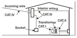
Measurement categories (Over-voltage categories)
To ensure safe operation of measuring instruments, IEC61010 establishes safety standards for various electrical environments, specified as CAT I through CAT IV, and called measurement categories. Higher-numbered categories correspond to electrical environments with greater momentary energy, so a measuring instrument designed for CAT III environments can endure greater momentary energy than one designed for CAT II.
- CAT I: Secondary electrical circuits connected to an AC electrical outlet through a transformer or similar device.
- CAT II: Primary electrical circuits of equipment connected to an AC electrical outlet by a power cord.
- CAT III: Primary electrical circuits of the equipment connected directly to the distribution panel, and feeders from the distribution panel to outlets.
- CAT IV: The circuit from the service drop to the service entrance, and to the power meter and primary over current protection device (distribution panel).
- Avoid placing the meter in areas where vibration, dust or dirt is present. Do not store the meter in excessively hot, humid or damp places.
- This meter is a sensitive measuring device and should be treated with the same regard as other electrical and electronic devices.
- When the meter is not in use keep the meter turned off to keep the battery from discharging.
- When disconnecting the test leads from the unit, always grasp the leads where the input jacks meet the tester housing.Do not pull the leads out of the jacks by the insulated wire or transport the tester using the test leads as a carrying strap.
|
Symbols |
|
 |
Caution, risk of danger, refer to the operating manual before use |
 |
Caution, risk of electric shock |
| AC (Alternating Current) | |
| DC (Direct current) | |
| AC/DC Selectable (Alternating Current/Direct Current) | |
 |
Earth (ground) Terminal |
 |
The equipment is protected throughout by double insulation or reinforced insulation |
 |
Application around and removal from hazardous live conductors is permitted. |
 |
Conforms to Standards of European Union |
 |
Designates the product as recyclable electronic waste per WEEE Directive |
3 SPECIFICATIONS
-
- MEASURING RANGE & ACCURACY
AC CURRENT
| RANGE | RESOLUTION | ACCURACY |
| 200uA | 0.1uA |
±(1.0% + 3) |
| 20mA | 10uA | |
| 200mA | 100uA | |
| 10A | 10mA | ±(2% + 3) |
- Frequency Response: 40Hz – 400Hz
AC VOLTAGE
| RANGE | RESOLUTION | ACCURACY |
| 200V | 100mV | ±(0.8% + 5) |
| 600V | 1V | ±(1.5% + 5) |
- Frequency Response: 40Hz – 400Hz
RESISTANCE
| RANGE | RESOLUTION | ACCURACY |
| 200.0W | 0.1W |
±(0.8%+3) |
| 2.000KW | 1W | |
| 20.00kW | 10W | |
| 200.0kW | 100W | |
| 2.000MW | 1kW | ±(1.2%+5) |
DC CURRENT
| RANGE | RESOLUTION | ACCURACY |
| 200uA | 0.1uA |
±(0.8% + 3) |
| 20mA | 10uA | |
| 200mA | 100uA | |
| 10A | 10mA | ±(1.2% + 5) |
DC VOLTAGE
| RANGE | RESOLUTION | ACCURACY |
| 200.0mV | 0.1mV | ±(0.7%+5) |
| 2.000V | 1mV |
±(0.5%+5) |
| 20.00V | 10mV | |
| 200V | 0.1V | |
| 600V | 1V | ±(0.8%+5) |
CONTINUITY TEST
| RANGE | RESOLUTION | ACCURACY |
 |
0.1W |
£10W Buzzer beep
10W-70W Buzzer may or may not beep ³70W No buzzer beep |
DIODE
| RANGE | RESOLUTION |
 |
The approximate forward voltage drop of the diode will be displayed |
4 FUNCTIONS
- HOLD BUTTON
- Press HOLD once to enter data hold mode and freeze the displayed value.
- Press HOLD again to exit data hold mode and resume normal measurement mode.
2 AUTO POWER OFF
1. If you have not operated the meter for 15 minutes, the meter will turn off automatically and go into Sleep mode.It will beep 1 minute prior to turning off as a warning. To wake the meter from Sleep mode, turn the rotary switch or press a button.
5 DIAL SETTINGS
- AC VOLTS
To avoid personal injury or damage to the meter, do not attempt to measure voltages higher than 600V AC.
- Insert the black (negative) test lead into the COM input terminal.
- Insert the red (positive) test lead into the INPUT terminal to the right of the COM terminal.
- Set the Rotary Switch to
- Touch the test leads to the circuit under test. With AC voltage, the polarity of the test leads is not a factor. Note: It is best to touch one of the test leads to ground or neutral first and then touch the 2nd test lead to the hot wire.
- Read the value of the measurement displayed.
- Typical AC Voltage measurements include wall outlets, appliance outlets, motors, light fixtures and switches.
2 DC VOLTS 
To avoid personal injury or damage to the Meter, do not attempt to measure voltages higher than 600 VDC.
- Insert the black (negative) test lead into the COM input terminal.
- Insert the red (positive) test lead into the INPUT terminal to the right of the COM terminal.
- Set the Rotary Switch to
- Touch the test leads to the circuit under test. Touch the black (common) test lead to the negative DC source (ground) first and red (positive) test lead to the “live” source second.
- Read the value of the measurement displayed. If the leads are reversed a indicator will appear on the display.
- Typical DC Voltage measurements include car batteries, automotive switches, motors, and household batteries.
3 AC AMPS  If the fuse burns out during measurement, the meter may be damaged or personal injury may occur. To avoid possible damage to the meter or to the equipment under test, check the meter’s fuses before measuring current. Use the proper terminals, function, and range for the measurement. Never place the test leads in parallel with any circuit or component when the leads are plugged into the current terminals. Do not attempt to measure current exceeding 10A AC. If you are not sure if the current exceeds 10A do not attempt to measure current with this meter.
- Insert the black (negative) test lead into the COM input terminal.
- Insert the red (positive) test lead into the 10A terminal to the left of the COM terminal for current measurements greater than 200mA AC. Insert the red (positive) test lead into the INPUT terminal to the right of the COM terminal for current measurements of 200mA AC or less.
- Set the Rotary Switch to
- Press the “SELECT” button until AC is shown on the display.
- Turn off power to the circuit to be measured.
- Open the circuit to be measured.
- Touch the red test lead to one side of the break in the circuit and the black test lead to the other side of the break in the circuit. For AC Amp measurements the polarity of the leads does not matter.
- Return power to the circuit.
- Read the amps on the display. Note: When measuring AC Amps this meter displays the effective value of the sine wave (mean value response). When the measured current is <5 amps continuous measurement is acceptable. When the measured current is 510 amps do not exceed 10 seconds of continuous measurement. Wait 15 minutes before performing additional current measurements. Always turn off power to circuit and remove the leads from the circuit before removing and reinserting the leads into the meter’s input terminals. Once the measurement is complete, immediately remove the test leads from the circuit under test and remove the test leads from the input terminals of the meter.
4 DC AMPS  If the fuse burns out during measurement, the meter may be damaged or personal injury may occur. To avoid possible damage to the meter or to the equipment under test, check the meter’s fuses before measuring current. Use the proper terminals, function, and range for the measurement. Never place the test leads in parallel with any circuit or component when the leads are plugged into the current terminals. Do not attempt to measure current exceeding 10Amps DC. If you are not sure if the current exceeds 10Amps do not attempt to measure current with this meter.
- Insert the black test (negative) lead into the COM input terminal.
- Insert the red (positive) test lead into the 10A terminal to the left of the COM terminal for current measurements greater than 200mA AC. Insert the red (positive) test lead into the INPUT terminal to the right of the COM terminal for current measurements of 200mA AC or less.
- Set the Rotary Switch to
- Press the “SELECT” button until DC is shown on the display.
- Turn off power to the circuit to be measured.
- Open the circuit to be measured.
- Touch the red test lead to the positive side of the break in the circuit and the black test lead to the negative side of the break in the circuit for DC Amp measurement.
- Return power to the circuit.
- Read the amps on the display. Note: When the measured current is <5 amps continuous measurement is acceptable. When the measured current is 510 amps do not exceed 10 seconds of continuous measurement. Wait 15 minutes before performing additional current measurements. Always turn of power to circuit and remove the leads from the circuit before removing and reinserting the leads into the meter’s input terminals. Once the measurement is complete, immediately remove the test leads from the circuit under test and remove the test leads from the input terminals of the meter.
5 RESISTANCE  When measuring resistance always make sure the power to the circuit is off.
- Insert the black (negative) test lead into the COM input terminal.
- Insert the red (positive) test lead into the INPUT terminal to the right of the COM terminal.
- Set the Rotary Switch to (ohms).
- Touch the test leads to the resistor or non-energized component to be measured.
- Read the value of the measurement displayed. With resistance measurements, the polarity of the test leads is not a factor.
- Typical resistance measurements include resistors, potentiometers, switches, extension cords and fuses.Note: For measurements > 1M, the meter may take a few seconds to stabilize reading. This is normal for high resistance measurements. When the input is not connected, i.e. at open circuit, ” OL” will be displayed as an overrange indication.
6 CONTINUITY ![]() To avoid damages to the Meter or to the devices under test, disconnect circuit power and discharge all the high-voltage capacitors before measuring resistance. Do not input 60V DC or 30V AC to avoid personal harm. Do not use on energized circuits.
To avoid damages to the Meter or to the devices under test, disconnect circuit power and discharge all the high-voltage capacitors before measuring resistance. Do not input 60V DC or 30V AC to avoid personal harm. Do not use on energized circuits.
- Insert the black (negative) test lead into the COM input terminal.
- Insert the red (positive) test lead into the INPUT terminal to the right of the COM terminal.
- Set the Rotary Switch to
- Press the SELECT button until is shown on the display.
- Connect the test leads across with the object being measured.
- The buzzer sounds continuously if the resistance of a circuit under test is <~10. It indicates the circuit connection is good.
- The buzzer does not sound if the resistance of a circuit under test is >70. It indicates a possible broken circuit.
- The buzzer may or may not sound if the resistance of a circuit under test is 10 -70.
- Read the resistance value on the display.
- Typical continuity measurements include switches, extension cords and fuses. Note: Open circuit voltage is around 2V. When the input is not connected, i.e. at open circuit, ” OL” will be displayed as an over range indication.
7 DIODE ![]()
- Insert the black test (negative) lead into the COM input terminal.
- Insert the red (positive) test lead into the INPUT terminal to the right of the COM terminal.
- Set the Rotary Switch to
- Press the SELECT button until is shown on the display.
- For forward voltage drop readings on any semiconductor component, place the red test lead on the component’s anode and place the black test lead on the component’s cathode.
- Read the resistance value on the display. Note: When measuring resistance, the circuit should be powered off and all capacitors should be completely discharged prior to testing. A more accurate measurement can be achieved by separating the component from the circuit being tested. When the test leads are not connected or are reversed, the display will show an over-range symbol “OL”.
8 BATTERY ![]()
- Insert the black (negative) test lead into the COM input terminal.
- Insert the red (positive) test lead into the INPUT terminal.
- Set the Rotary Switch to
- The meter can test either 1.5V or 9V batteries. Set the rotary switch to the battery being tested.
- Touch the black (common) test lead to the negative (-) terminal on the battery and the red test lead to the positive (+) terminal on the battery.
- Read the value of the measurement displayed. If the leads are reversed a “-” indicator will appear on the display.
6 BATTERY REPLACEMENTTo avoid false readings, which could lead to possible electric shock or personal injury, replace the battery as soon as the battery indicator ![]() appears.
appears.
- Disconnect the connection between the test leads and the circuit under test, and remove the test leads from the input terminals of the meter.
- Turn the Meter power off.
- Remove the screw from the battery cover on the back of the meter. Slide the battery cover off.
- Replace the old batteries with 2 fresh AAA batteries. Note: Do not use rechargeable batteries in this unit.
- Carefully slide on the battery cover and tighten the screw. Do not overtighten the screw as this may strip the threads in the meter housing.
7 GENERAL SERVICE
- Periodically wipe the case with a damp cloth and mild detergent. Do not use abrasives or solvents
- To clean the terminals use a cotton swab and detergent, as dirt and moisture in the terminals can affect readings.
- Turn the Meter power off when it is not in use.
- Take out the battery when it is not used for a long time.
- Do not use or store the Meter in a place of humidity, high temperature.
SPERRY INSTRUMENTS LIMITED LIFETIME WARRANTY
Subject to the exclusions and limitations detailed below, Sperry Instruments provides a limited lifetime warranty on products of its manufacture will be free from defects in materials and workmanship under normal use and service.Limited Limited means that Sperry Instruments warrants to the original purchasers of products from Sperry Instruments authorized distributors at the time of shipment such products shall be free of defects in material and workmanship while the tool is used under normal working conditions. Standard wear and tear, dulling over time, overloading, misuse, and acts of God are not covered under warranty. This warranty does not cover batteries, fuses, or test leads.When a warranty claim arises, the purchaser must contact Sperry Instruments. If the defect comes under the terms of this limited warranty, Sperry Instruments will arrange, at its sole discretion, one of the following options:
- Product will be replaced The purchaser is solely responsible for determining the suitability of Sperry products for the purchaser’s use or resale, or for incorporating them into articles or using them in the purchaser’s applications. The distributor is authorized to extend the foregoing limited warranty to its original purchasers in connection with the sales of Sperry products, provided that such products shall not have been altered by the distributor. The distributor shall be fully responsible for any warranties the distributor makes to its purchasers which are broader or more extensive than Sperry’s limited warranty.
Lifetime Warranty
Warranty Limitation: The forgoing warranties are exclusive and are in lieu of all other express and implied warranties whatsoever, including but not limited to implied warranties of merchantability and fitness for a particular purpose. The foregoing warranties do not cover ordinary wear and tear, abuse, misuse, overloading, alterations, products which have not been installed, operated or maintained in accordance with Sperry’s written instructions. Test leads, fuses, batteries and calibration are not covered under any implied warranty. “Lifetime” of products that are no longer offered by Sperry will be either repaired or replaced with an item of Sperry Instruments choice of similar value. Lifetime is defined as 5 years after Sperry discontinued manufacturing the product, but the warranty period shall be at least ten years from date of purchase. Original proof of purchase is required to establish original ownership of product. No warranty will be honored unless an invoice or other proof of purchase date is provided to Sperry Instruments. Hand written receipts or invoices will not be honored.
Test Equipment Depot – 800.517.8431
99 Washington Street Melrose,MA 02176 TestEquipmentDepot.com
[xyz-ips snippet=”download-snippet”]