Datasheet
Vertex Channel Emulator
Spirent
The world’s most scalable channel emulation platform, Spirent’s Vertex channel emulator is an advanced test and measurement system that accurately simulates the complex effects of signal fading on wireless transmissions.The system enables the test and evaluation of a broad range of applications with a variety of channel densities, from basic applications like 2-channel SISO to complex, high channel density applications like MIMO OTA, MIMO beamforming and carrier aggregation needed for 5G test scenarios.
The Vertex platform combines modularity, scalability and ease-of-use into a powerful test and measurement solution that addresses the needs of a constantly evolving wireless market.
Applications
- Scalable from basic SISO to high channel density applications– MIMO beamforming– MIMO OTA– Carrier aggregation– Massive MIMO
- Device conformance and performance verification
- Virtual drive testing
- Mesh networks
- Satellite and aeronautical applications
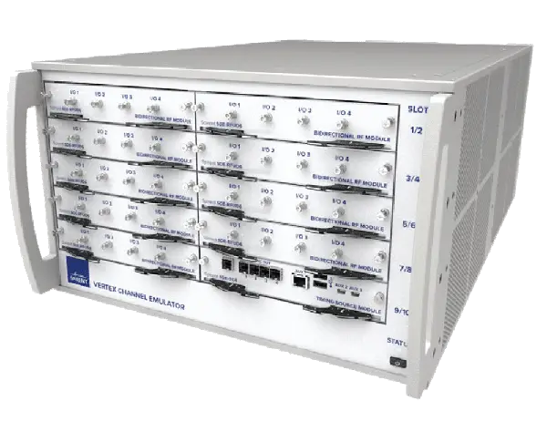
Spirent Vertex® Channel Emulator
The Vertex® channel emulator is an advanced platform that replicates the comprehensive noise and spatial conditions of even the most complex wireless channels. Its cutting edge capabilities enable users to emulate a real-world RF environment in the lab, making it possible to isolate and identify performance issues early in the development cycle.
Vertex is backed by a long history of channel emulation leadership and industry-recognized expertise. Incorporating a modular RF front end with a powerful signal processing core, the Vertex channel emulator achieves an unprecedented level of scalability and flexibility, enabling it to efficiently address a broad range of applications from low channel density like SISO or 2×2 MIMO to high channel density required for 5G scenarios, such as MIMO beamforming, MIMO OTA, carrier aggregation, and massive MIMO.
Easy to set up and operate, Vertex includes Spirent’s industry-recognized user-friendly graphical user interface that allows measurements to be set up and performed quickly and accurately.
Features & Benefits
Scalability
The Vertex Channel Emulator is scalable to a broad range of applications. The hardware is capable of supportingas few as two bidirectional RF channels for basic RF testing, and up to as many as 32 unidirectional RF channels to support high channel density such as MIMO OTA, all in one single, small form instrument.

Modularity
Separate RF modules are optimized for unidirectional or bi-directional applications and support a variety of different frequency bands. This allows the Vertex Channel Emulator to be configured for specific test needs using minimal hardware. Field-replaceable RF and DSP modules facilitate upgrades and enhance serviceability.
High Channel Density in a Compact Space
The Vertex Channel Emulator system supports up to 36 RF ports and 256 digital links in one 6U rack height. It enables more efficient use of hardware for tests that require higher RF channel counts.
Comprehensive Channel Modeling Support
The built-in Vertex propagation library offers a vast selection of standard channel models, while making it easy to edit and save changes to both the standard as well as user-defined models. Classical and 2D/3D geometrical channel models are supported and the independent channel modeling feature allows one Vertex to support up to 16 nodes for mesh network applications.
Ease of Use
Complicated test setups are made simpler with an easyto-use Graphical User Interface (GUI). Intuitively-designedlibraries of connection setups make it easy to navigate through complicated configurations by presenting information in a clear way. For debugging purposes, important Information is displayed in real time, including power level tracking of each RF port.
Remote Programming Interface (RPI)
Remote programming is supported through TCP/IP with both telnet or SSH protocol. The RPI commands provide seamless backward compatibly to the Spirent VR5 HD channel emulator.
Live Streaming Dynamic Environment Emulation (LSDEE)
Live Streaming Dynamic Environment Emulation is an advanced feature addition to the Vertex Channel Emulator RPI. It provides a very high-speed control mechanism for an extensive set of emulation parameters.
Unlike traditional DEE, which allows a user to create predefined scenarios for modifying channel parameters during a test run, there is no requirement to predefine or pre-compile channel emulation states or inter-state durations. LSDEE reduces processing time and monitors device behavior to make real-time scenario adjustments. This is extremely beneficial for high-speed scenarios where manual intervention can interfere with time-sensitive environmental changes. The same set of emulation parameters can be supported as with traditional DEE.
Key Test Applications
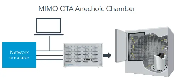
MIMO OTA
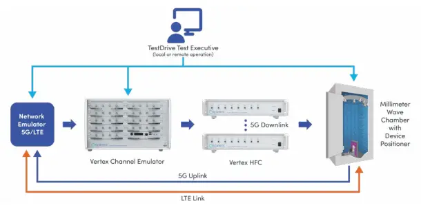
MIMO OTA applications require high channel density, based on the number of probes used in the test setup. The Vertex channel emulator can be used in both anechoic and reverberation chamber test setups and can switch between chamber types in minimal time. For anechoic chambers, Vertex supports up to 32 RF probes and two carriers with 16 dual polarized probes or 8 dual polarized probes on one instrument. For reverberation chambers, up to four carriers can be aggregated on one instrument.
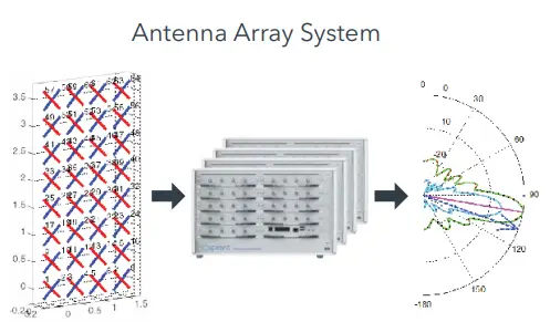
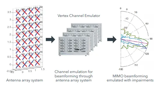
AAS, Massive MIMO and MIMO Beamforming
Up to 8 Vertex instruments can be integrated into one system with the Vertex Baseband Synchronizer (VBS). With the VBS, the Vertex units in a system can work standalone or all together as a complete solution for massive MIMO applications with real-time or IQ playback fading.
Carrier Aggregation
Supporting up to four 2×2 bi-directional carriers on one instrument, Vertex can be used for carrier aggregation scenarios. Each radio link can be independently modelled, simulating channel conditions to represent multiple carriers on the same eNodeB or from different eNodeB’s. The same setup can also be used for simulating channel conditions that trigger handovers and on Coordinated Multipoint (CoMP) applications as well.
Virtual Drive Testing
Supporting up to sixteen SISO cells or eight 2×2 MIMO cells on one instrument, Vertex accurately reproduces real network propogation conditions in the lab.
The ability to emulate a high number of cells, combined with Spirent’s Live2Lab® Virtual Drive Test-Conversion Tool (Live2Lab VDT-CT) software, makes the laborious process of drive testing easy and repeatable. Live2Lab VDT-CT can convert a large variety of log file types (QXDM, JDSU, Accuver, Transcom, Anite Nemo, etc.) into reproducible drive route simulations in a lab environment. Additionally, Vertex allows easy debugging of power level issues by allowing users to dynamically monitor the power level on each port.
Mesh Networks
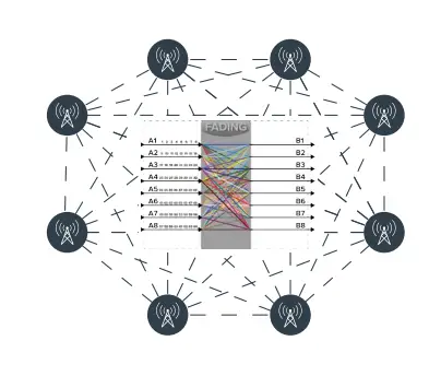
Mesh network applications require each node to independently communicate with each other. From a channel emulation perspective, this implies that each radio link needs to be emulated with a different fading profile simultaneously, placing heavy demand on the number of RF antenna ports required in addition to the processor load. Vertex supports up to 16×16 independent channel models on a single instrument, providing the capability to test up to a sixteen node mesh network.
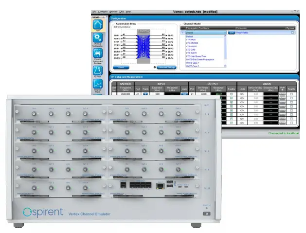
Graphical User Interface
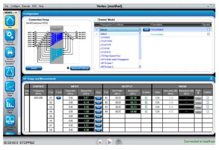
For users familiar with Spirent’s VR5 HD Channel Emulator, the Vertex Channel Emulator presents a seamless transition, as it has been developed with the same GUI features. The Vertex GUI is very easy to use and presents clear and concise information even for the first-time user. The GUI can be accessed using a cable hooked up to the Vertex display port or through the controller laptop. Connection setup and RF parameters for channel modeling can be easily configured to run in real-time mode. A comprehensive set of ready-to-run standard models is provided, making it easy to select and play. Setup of most test cases is a matter of using a few mouse clicks and drop down menus.
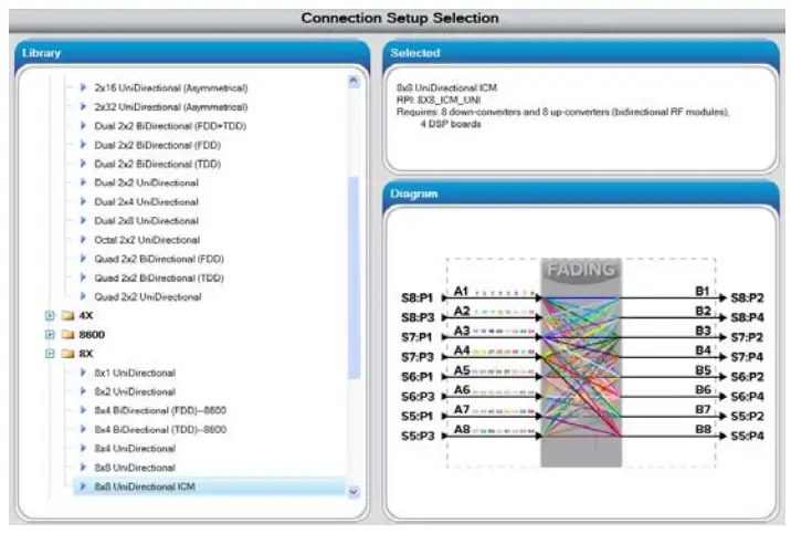
The GUI provides an easy-to-read display for high channel density features that can be complicated to set up. For example, the connection setup for an 8×8 MIMO application, or 64 radio links, can be easily viewed using the pre-loaded option from the Connection Setup library.

Configuring the MIMO correlation matrix is easy and convenient to do on the Vertex GUI. Complicated matrices such as a 2×8 configurations can be created using spreadsheet-type entries, rather than spending the time writing elaborate test scripts for creating the correlation matrices.
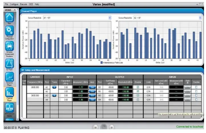
The Vertex GUI displays real-time information regarding channel power with respect to fading. This instantaneous display enables quick detection of deviations from expected behavior and the ability to efficiently debug problems.
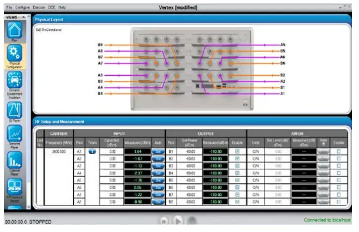
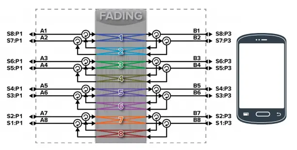
The cable connection diagram built-in to the Vertex GUI presents the actual cabling connections that need to be made. This feature makes it easy to cable complicated connection setups and minimizes cabling error. The image shown is the cabling setup for an 8×8 unidirectional configuration.
Additionally, the built-in temporal player feature facilitates real-time tracking of power levels at each port. This is especially useful for handover scenarios, which are based on power levels between the serving cells.
Technical Specifications
- RF configuration• With bidirectional module: from SISO up to 8×8 MIMO with bidirectional fading• With unidirectional module: up to 2×32 and dual 2×16• Multiple instruments: Two instruments can be fully integrated into a system; additional instrumentscan be synchronized for more complex connection setups.
- RF inputs : Up to 18
- RF outputs : Up to 32
- Digital channels : Up to 256 (40MHz or 100MHz bandwidth); up to 64 (200MHz bandwidth)with a single Vertex instrument
- Bandwidth : 40MHz, 100MHz, 200MHz, 400MHz, 600MHz
- Frequency range : 30MHz to 5925MHz
- RF input Input level range: -50 to +15dBm
- Level resolution: 0.1dB
- Damage level: +33dBm (Peak)
- RF output level Min/max range: -110 to -10dBm (RMS)
- Resolution: 0.1dB
- Input and output power meters :Modes:• Continuous• RF burst-triggering for gated input signals
- Residual EVM : -40dB typical
- Residual noise : Better than -165dBm/Hz at a set output level of -45dBm
- RF port VSWR : 1.5:1
- Independent paths : Up to 24 paths per digital channel
- Delay : 0 to 1s at bandwiths >=100MHz; 0 to 2s at bandwiths =40MHz; 0.1ns resolution
- Relative path loss : 0 to 40dB
- Dynamic channel parameters :• Sliding delay (moving propagation)• Birth-death delay• 3GPP High-Speed Train (HST) profiles log normal (shadow fading)
- Dynamic Environment Emulation (DEE) and Live Streaming DEE (LSDEE)Controllable parameters:State duration, channel output level, AWGN on/off, C/N, path on/off, relative power and delay,LOS AoA, K factor, frequency shift, Doppler velocity, MIMO branch phase, power imbalance, andcorrelation, link phase and loss, bulk delay, path phase, geometrical charactersChannel model update rate: 100 times per secondStart method: Triggered, free playPlay method: Run for N loops, wrap around
- Standards-based models : LTE, Wi-Fi (802.11a/b/g, 802.11n, 802.11 ac, 802.11 ax), IMT-A, WiMAX, UMTS, CDMA2000®, HSPA, GSM, SCM/SCME (ITU-R M.2135), WINNER, Butler, 5G TDL and CDL, D2D
- Custom models : Easy-to-use interface allows the user to create custom channel models or edit any of the standard channel models in the library
- Fading mode : Classical, GCM, 3D GCM, MIMO OTA
- Real-time fading Types: Rayleigh, Rician, pure Doppler, frequency shift, phase shiftFading Doppler: Up to 12kHzDoppler frequency shift: -2MHz to 2MHzRepetition interval: >7 daysRelative phase: 0-360°, 0.1° resolutionRician K factor: -30 to +30dBLevel crossing rate (LCR) accuracy: < ±2.5% deviation from theoretical LCR curve of the simulated vehicle velocityFading power spectrum: classical 6dB, flat, classical 3dB, rounded, rounded 12dB, bellCorrelation: programmable complex correlation between paths
- IQ-playback fading : Supports IQ playback fading
- AWGN : C/N Ratio: -40 to +40dBAccuracy: ±0.1dBBandwidth: up to 400MHzSettable modes: C/N, Eb/No, N
- Control interface : PC-based graphical user interfaceRemote programming through ethernet
- 10MHz internal reference accuracy : 1ppm
About Spirent Communications
Spirent Communications (LSE: SPT) is a global leader with deep expertise and decades of experience in testing, assurance, analytics and security, serving developers, service providers, and enterprise networks. We help bring clarity to increasingly complex technological and business challenges. Spirent’s customers have made a promise to their customers to deliver superior performance. Spirent assures that those promises are fulfilled. For more information visit: www.spirent.com
Americas 1-800-SPIRENT+1-800-774-7368 |
Europe and the Middle East+44 (0) 1293 767979 |
Asia and the Pacific+86-10-8518-2539 |
© 2020 Spirent Communications, Inc. All of the company names and/or brand names and/or product names and/or logos referred to in this document, in particular the name “Spirent” and its logo device, are either registered trademarks or trademarks pending registration in accordance with relevant national laws. All rights reserved. Specifications subject to change without notice.
Read More About This Manual & Download PDF:
Vertex Channel Emulator Datasheet –
Vertex Channel Emulator Datasheet –
Questions about your Manual? Post in the comments!
[xyz-ips snippet=”download-snippet”]