![]()
 M.5055-CHANNEL CLUB MIXERUser Manual
STANTON MAGNETICS, INC.[email protected]• +1 954.689.8833www.stantondj.com
INTRODUCTION
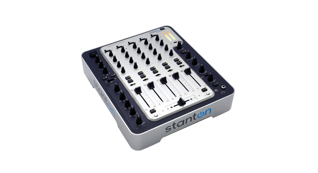
Congratulations and thank you for purchasing the latest addition to the growing Stanton family. Sporting a new attitude, and a fresh, modern look, the M.505 is a 5-channel mixer loaded with features and innovations giving club and mobile DJs a complete, powerful, yet simple tool to mix, create, and perform their best. Thoughtfully designed and engineered to give you the most intuitive and instinctual experience possible, the M.505 is packed with features in a logical layout with quality components, all at an affordableprice.
PLEASE READ CAREFULLY BEFORE USE
FAILURE TO FOLLOW THE INSTRUCTIONS PRINTED BELOW MAY VOID THE WARRANTY
- Follow all security advice printed on your mixer
- When removing the unit’s AC plug from the power source, grasp and pull the plug, NEVER the cord itself!
- Avoid placing your mixer near heat sources, such as power amplifiers.
- When in use, place your mixer on a stable surface, away from vibration. Always use care when carrying your mixer.Impact or heavy vibration may compromise the unit’s mechanical integrity. The manufacturer is not responsible for damage resulting from an impact, or misuse.
- When in use, place your mixer away from sources of hum or noise, such as transformers, or electric motors.
- To prevent overheating, always provide your mixer with adequate ventilation air space.
- Avoid stepping on your mixer’s AC cord. Repeated compression of the cord may lead to electrical shorting.
- To avoid damage due to AC voltage peaks, always disconnect your mixer from the power source during electrical storms.If possible connect the mixer to a surge protector.
- Your mixer contains no user-serviceable parts. The manufacturer is not responsible for any damage or personal injury resulting from unauthorized user-servicing or modifications. In addition, the warranty will be void if any unauthorized service by the user is detected.Always return your mixer to an authorized Stanton dealer for servicing.
SUPERIOR SOUND TECHNOLOGY
Stanton’s revolutionary Superior Sound Technology (SST™) also gives the M.505 exceptional sound quality with audio specifications rivaling mixers costing up to four times as much. Developed from the ground up by a team of seasoned audio professionals who have designed world-class professional recording studio and broadcast mixers, working hand in hand with experienced and respected DJs, SST™ delivers a dynamic range better than 110 dB through ultra-low-noise circuitry with a lower total harmonic distortion (THD) than other mixers in its’ class. Glass epoxy PC boards, surface mount technology, and faders that don’t bleed add to the superior construction standards.This equates to a cleaner, more transparent sound, allowing your music to be heard the way it was meant to.We’re proud to bring you the new look, feel, and sound of Stanton.
DESCRIPTION OF FEATURES
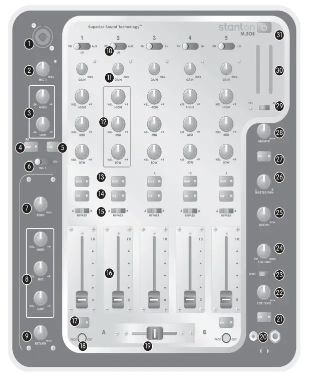
- Mic 1 Input: Combo connector to plug-in XLR or TRS (tip, ring, sleeve) 1/4” microphone cables.
- Mic 1 Level: Controls the level of the microphone connected to (1) mic 1 Input.
- Mic 1 EQ: Adjusts the high and low frequencies of the signal coming from mic 1. Note: Any changes made to EQ settings will affect the overall output level of the microphone.
- Mic 1 Effect Send: Sends the mic 1 signal to outboard sound processors connected via the Send & Return circuit.
- Mic 1 Talkover: Attenuates mic 1’s level by 20dB.
- Mic 1 On-Off: Turn mic 1’s signal on and off.
- Effect Send Level: Controls the level of the signal sent to the outboard sound processor via the channel sends (13) or mic 1 send (4).
- Effect Send EQ: Adjust the high, mid, and low frequencies of the signal sent to the outboard sound processor via the channel send (13) or mic 1 send (4). Note: Any changes made to EQ settings will affect the overall send level.
- Effect Return Level: Controls the level of the signal returning from the outboard sound processor.
- Input Selection: Each input channel features several input sources. These selector switches let you toggle between the various sources. All channels have a phono and line input. Channels 1-2 also have an AUX input which can be switched from mic to line.
- Input Channel Gain: Controls the input level of the selected audio source for each channel. Each gain control has an LED clip indicator.• TIP: Turn the gain knob until the LED flashes lightly to the beat of the music. If the LED is constantly on, the signal is too loud and the audio may get slightly distorted.
- Input Channel EQ: Adjusts the high, mid, and low frequencies of the input source. Note: Any changes made to EQ settings will affect the overall gain of the input source.
- Input Channel Effect Send: Sends the signal from each channel to the outboard sound processor connected via the effects Send & Return.
- Cue Selection: Sends the audio for each channel pre-channel fader to the headphone output.
- Crossfader Assign:Assigns each channel to either side (Aor B) of the crossfader (CF). Set to Bypass if you do not want to use the crossfader.
- Input Channel Level Fader: Controls the output level of each channel.
- Crossfader Return: Returns the wet signal from the sound processor to either side of the crossfader. When an outboard signal processor is connected via the Send & Return circuit, the crossfader can be used to mix the dry signal with the audio coming back from the sound processor (wet signal). This is done by assigning the channel sent to the sound processor to one side of the crossfader, and turning on the crossfader return (17) on the opposite side of the crossfader.• TIP: Press the SEND button on channel 1. Set the channel 1 CF to assign to A. Turn on the RTN on side B of the crossfader.Make sure no other channel is assigned to the crossfader while mixing the effects in and out. Slide the crossfader from A to B. Once side B is reached, the wet signal is audible.
- Crossfader Curve Control: Adjusts the curve of the CF from a long fade to a sharp cut in for quick mixing and scratching. Each side of the crossfader has an independent curve control.
- Crossfader: Fades between any input channels assigned via the CF assign switches (15).
- Headphone Outputs: Connect your headphones to either 1/8” or _” connector (or both for dual headphones).
- Effects Cue Return: Returns the signal from the sound processor to cue it before sending it to the master or crossfader.
- Cue Level: Controls the level of the headphone output.
- Cue Split: In the split position, the PFL signal is sent to the left ear, and the PGM (Master) signal is sent to the right ear.To hear both signals in this position, the cue pan must be set to the center position.
- Cue Pan: Mixes between the selected channel (PFL) and the master output (PGM).
- Booth Level: Controls the level of the booth output.
- Master Output Pan: Pans the master output left to right.
- Effects Master Return: Returns the wet signal from the outboard sound processor to the master output.
- Master Output Level: Controls the overall output level of the mixer.
- Level Meter Assign: Assigns the level meter to display the master output level (Master) or the pre-fader input level of any cued channels (PFL).
- Level Meter: Displays the input or output levels of the mixer depending on the setting of the Level Meter Assign (29).
- Power Switch Turns the mixer on and off.

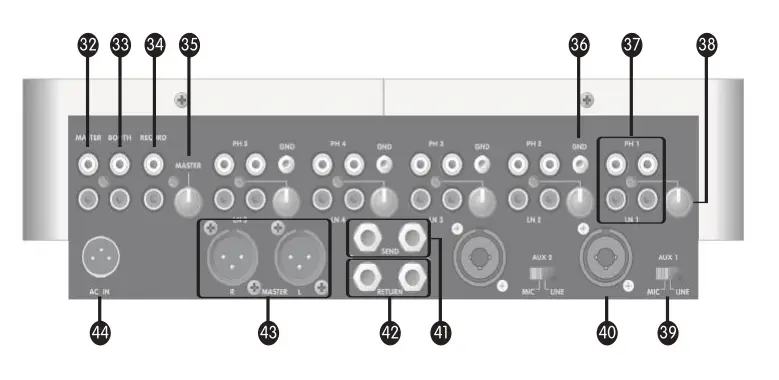
- Unbalanced Master Output: RCA connectors for the master output. Connect to an audio receiver or mixer equipped with RCA inputs.
- Booth output: RCA connectors for the booth output. This is just another output, although mostly used to monitor the audio in a DJ booth.
- Record output: This output is used to record audio in order to set the master level without affecting the record level.
- Master Trim: Attenuates the overall output of the mixer. This is useful in club situations to restrict the audio from clipping or overloading the sound system.
- Ground posts: Connect to the ground post of the turntable(s).
- Channel inputs: Connect your turntables and/or CD players to any of the channel inputs.• Which inputs do I use?o Phono inputs are only used when connecting turntables.o Line inputs are used with most common audio devices such as CD players, MP3 players, Samplers, etc.o Mic inputs are used to connect microphones.
- Channel Trims: In a similar fashion as the master trim, the input trims are used to attenuate the audio coming into each channel. Again, this is useful in club settings to restrict DJs who may be unfamiliar with the unit from overloading the inputs.
- AUX Input Selector: Switches the AUX inputs between line and microphone level.
- AUX Inputs: Combo connector to plug-in XLR or TRS (tip, ring, sleeve) 1/4” cables.• TIP: When using the AUX inputs at line level, you can connect any studio or P.A. gear equipped with TRS _” or XLR outputs by connecting the left output to AUX 1 and the right output to the AUX 2 input. You can then control the levels of the AUX inputs using channels 1 and 2 together.
- Effects Send: Connect to the input of your outboard sound processor.
- Effects Return: Connect to the output of your outboard sound processor.
- Balanced Master Outputs: Connect to your main sound system.
- AC In: Connect the included power supply.
CONNECTIONS
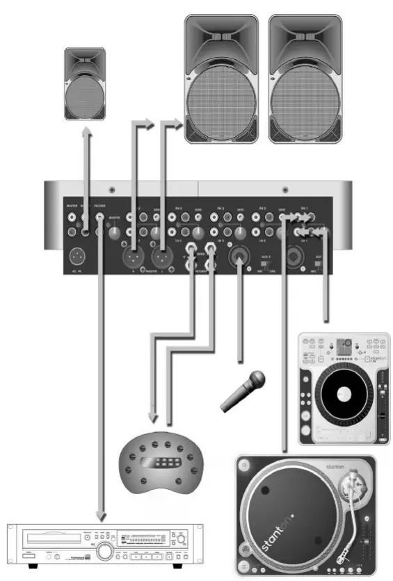
Inputs
- Connect the outputs of your turntables to the RCA phono inputs of your choice. If your turntables have ground connections, make sure to connect them to the ground posts on the mixer.
- Connect the outputs of your CD players to the RCA line inputs of your choice.
- If using a microphone, you can connect it to either the AUX jack on the back panel or to the dedicated microphone input on the top of the mixer. If you are using the AUX inputs, make sure the input switch is set to MIC. Line-level devices such as samplers and drum machines can be connected to the AUX inputs by switching the input selector to the line.
- If you are using an external effects unit, connect the SEND outputs to the inputs of your effects box, and the outputs of the effects box back into the RETURN inputs.
Outputs
- Connect the Master Output of the mixer to your sound system. Depending on the configuration of your system, you can use either the RCA or XLR connector – or both at the same time if necessary.
- If using the mixer in a live application, connect your DJ booth monitor system to the RCA booth outputs.
- You can connect the REC output directly to the input of a CD or cassette recorder or to a mixing board to record your set.
GETTING STARTED
- Once your system is set up, make sure the MASTER (28) is turned all the way down.
- Turn on the mixer and check your levels. Start with the channel faders (16) down, GAIN (11) and EQs (12) at 12 o’clock.Start the music. Adjust the GAIN until the LED indicator is blinking. You can also use the main LED meter to view the input level of each channel by setting the LEVEL METER ASSIGN (29) to PFL (Pre-Fader Listen) and pressing the CUE button on the channel you want to monitor.
- Assign your channels of choice to either side of the crossfader (19) (or just leave it bypassed if you don’t want to use it) using the crossfader assign switches (15).
- Make sure your levels are properly set on your sound system and turn the MASTER volume to the desired level. Now you are ready to go.
USING EFFECTS
The M.505’s send and return circuit was designed to enable DJs to use the crossfader as a wet/dry mix control.
- Once you have connected your effects box as indicated above, select the channel you want to process by pressing the SEND (13) button.
- Adjust the SEND LEVEL (7) and SEND EQ (8) as desired, making sure you have a good signal going into the effects box.
- You can preview the effects in your headphones by engaging the CUE RETURN (21).
- Once you are ready to activate the effect you return it either to the crossfader by pressing the CROSSFADER RETURN (17) or directly to the master output by pressing the MASTER RETURN (27).
: Press the SEND button on channel 1. Set the channel 1 CF to assign to A. Turn on the RTN on side B of the crossfader.Make sure no other channel is assigned to the crossfader while mixing the effects in and out. Make sure your SEND and RETURN levels are set properly. Slide the crossfader from A to B. Once side B is reached, the wet signal is audible.
FADER REPLACEMENT
Replacing the Channel FadersTo replace the channel faders simply remove the 4 screws from the fader plates. Carefully lift the fader to disconnect it from the mixer. Align the 7-pin connector of the replacement fader with the connector on the mixer’s circuit board and push it down into place.
Replacing the CrossfaderRemove the two screws from the extremities of the crossfader plate. Do not remove the two inner screws, as that will separate the fader from its plate. Carefully lift the crossfader from the mixer and disconnect it by holding the ends of the connector and pulling. DO NOT PULL ON THE CABLES DIRECTLY or you will risk damaging them.
SPECIFICATIONS
Frequency Response……………………………………………..20 Hz to 20 kHz +/- 1 dBTHD+N (Line)…………………………………………………………..<0.008% at 1 kHzS/N Ratio: Ref to Max Output Level (Dynamic Range)…………………….>110 dBNoise Floor (Line Input to Any Output)(Unbalanced Out)………………………………………………………………….< -92 dBV(Balanced Out)……………………………………………………………………………..< -84 dBuCrosstalk(Line to Line, Phono to Line, Line to Phono)……………………………< -90 dB @ 1 kHzChannel Fader Kill………………………………………………………………..< -95 dB @ 1 kHzCross Fader Kill………………………………………………………………..< -92 dB @ 1 kHzMax Output Level…………………………………………………………………+18 dBV (Unbalanced)(Unity Gain- Line Input/Output)…………………………………… +26 dBu (Balanced)Mic EQ…………………………………………………………………………….+10 dB/-24 dBChannel EQ……………………………………………………………………..Hi +9 dB, -45 dB (Kill)Mid +9 dB, -35 dB (Kill)Low +9 dB, -55 dB (Kill)
Dimensions (LxWxD)………………………………………………..13.8” x 12.0” x 3.8”Weight (Unit)……………………………………………………………….6.42 Kgs
FADER REPLACEMENT PARTS
FadersCrossfader – CF505Channel Fader – LF505
Power SuppliesUS – PS16USEurope – PS16EUAustralia – PS16AUJapan – PS16JAUnited Kingdom – PS16UK
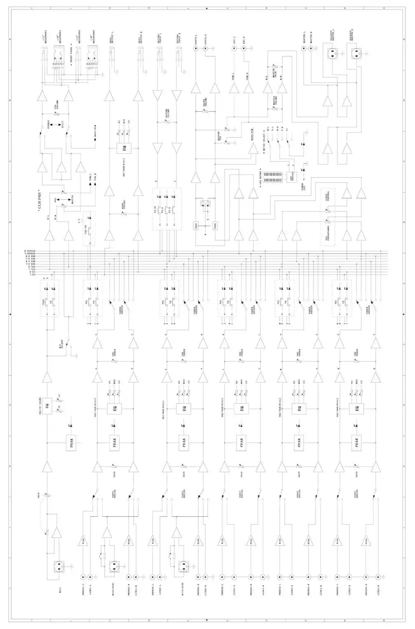
BLOCK DIAGRAM
WARRANTY & RETURN POLICY
 report this ad
Stanton Magnetics, Inc. – Warranty Provision – Returns for Repairs or Replacement
WarrantyThrough Stanton’s authorized dealers around the World, Stanton, or one of Stanton’s authorized distributors outside the U.S., will, without charge, repair or replace, at the sole discretion of the entity responsible for making the repair or providing the replacement, any Stanton merchandise proved defective in material or workmanship for a period of one (1) following the date of original purchase. Exceptions to this warranty are as noted below:The warranty for mechanical parts which are subject to wear and tear is limited to the earlier to occur of thirty (30) days following the date of original purchase or the following number of cycles: Faders – 15,000; Rotary potentiometers – 10,000; and Switches – 10,000.Stanton will warrant all replacement parts and repairs for ninety (90) days from the date of original shipment. Repairs made necessary by reason of misuse, alteration, normal wear, or accident are not covered under this warranty.
ReturnsAuthorized Stanton dealers are only authorized to sell and distribute merchandise within a specific country. All goods requiring warranty repair or replacement must be returned (freight prepaid if not hand-delivered) to the authorized Stanton dealer from whom the merchandise was purchased and in the same country where the merchandise was purchased. For purposes of purchases made via the Internet, the merchandise must be returned to the authorized Stanton dealer in the country where the authorized Stanton dealer which sold the merchandise to the purchaser is located and not the authorized Stanton dealer in the country where the purchaser is located or the country in which the merchandise was received. Any returns to a non-authorized dealer or to an authorized Stanton dealer not in the same country as the merchandise was intended to be sold or as set forth above will void this warranty.
To initiate a warranty repair, you must contact the authorized Stanton dealer from whom you purchased the merchandise, and follow such authorized Stanton dealer’s return policy.
Stanton assumes no risk and shall be subject to no liability for damages or loss resulting from the specific use or application made of the merchandise. Stanton’s liability for any claim, whether based on breach of contract, negligence, infringement of any rights of any party, or product liability and relating to the merchandise shall not exceed the price received by Stanton from your purchase of such merchandise. In no event will Stanton be liable for any special, incidental, or consequential damages (including loss of use, loss of profit, and claims of third parties) however caused, whether by the negligence of Stanton or otherwise.To the extent permitted by law and except as otherwise provided above, Stanton disclaims any express or implied warranties of merchantability or fitness for a particular purpose.The above warranty provides you with specific legal rights. You may also have additional rights, which are subject to variation from state to state and country to country.If there is a dispute regarding the warranty of merchandise that does not fall under the warranty conditions stated above, please include a written explanation with the merchandise when returned pursuant to the terms and conditions set forth herein.Please register your product online at www.stantondj.com or mail your completed warranty card toStanton Magnetics, Inc, 3000 SW 42 St. Hollywood, Florida 33312.
References
[xyz-ips snippet=”download-snippet”]