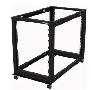
StarTech 4POSTRACKxU Adjustable 4 Post Open Frame Server Rack User Manual
Compliance Statements
Use of Trademarks, Registered Trademarks,and other Protected Names and SymbolsThis manual may make reference to trademarks, registered trademarks, and other protected names and/or symbols of third-party companies not related in any way to StarTech.com.Where they occur these references are for illustrative purposes only and do not represent an endorsement of a product or service by StarTech.com, or an endorsement of the product(s) to which this manual applies by the third-party company in question. Regardless of any direct acknowledgement elsewhere in the body of this document, StarTech.com hereby acknowledges that all trademarks, registered trademarks, service marks, and other protected names and/or symbols contained in this manual and related documents are the property of their respective holders.PHILLIPS® is a registered trademark of Phillips Screw Company in the United States or other countries.
Warning Statements
- Make sure that you assemble this product according to the instructions.
- Do not exceed the weight capacity of this product. Overloading this product might result in injury or property damage. This product can support the following weight: Stationary = 1200 lb. (544 kg) Rolling = 660 lb. (300 kg).
- This product is intended for indoor use only and should not be used outdoors.
- This enclosure is extremely heavy. Never attempt to move or lift this enclosure without assistance.
- Tipping hazard! Extending multiple components from this enclosure increases the chance that the enclosure will tip over. To avoid this risk, do not extend more than one component from the enclosure.
- Do not place any items on this enclosure and do not stack the enclosure on top of another enclosure.
- Keep liquid away from this enclosure.
- Make sure that you install the enclosure in an area that can handle the combined weight of the enclosure and the equipment that you intend to place inside of the enclosure.
- This product requires an earth ground connection. Do not use this product without an earth ground connection.
Product Diagram
Expanded View
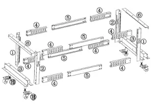
| 1 | Left Vertical Rails (x 2) | 5 | Center Sections (x 4) |
| 2 | Right Vertical Rails (x 2) | 6 | Top Brackets (x 2) |
| 3 | Base Brackets (x 2) | 18 | Casters (x 4) |
| 4 | Corner Sections (x 8) | 19 | Leveling Feet (x 4) |
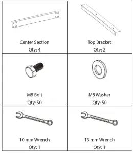
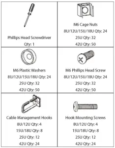
Package Contents
Requirements
For the latest requirements please visit www.startech.com/4POSTRACKxxU.
- Pliers (sold separately)
- 14 mm Wrench (sold separately)
- Two People (for assembly)
- Earth Ground Connection
- (Optional) Spirit/Bubble Level (sold separately)
Installation
Note: Two people are required for the Rack assembly.
Set the Mounting Depth
- Align the Corner Sections (x 2) with the Center Sections (x1) and slide the Corner Sections overtop of the Center Sections. (Figure 1)
- Determine the maximum required mounting depth for the Rack Mountable Equipment. Review the Mounting Depth Chart to determine the Setting Numbers that are requiredfor the application.
Mounting Depth Setting Numbers Mounting Depth Setting Numbers 22 in. 0 and 0 32 in. 5 and 5 23 in. 1 and 0 33 in. 5 and 6 24 in. 1 and 1 34 in. 6 and 6 25 in. 1 and 2 35 in. 6 and 7 26 in. 2 and 2 36 in. 7 and 7 27 in. 2 and 3 37 in. 7 and 8 28 in. 3 and 3 38 in. 8 and 8 29 in. 3 and 4 39 in. 8 and 9 30 in. 4 and 4 40 in. 9 and 9 31 in. 4 and 5 Mounting Depth Chart
- Slide the Corner Sections (x 2), inward along the Center Sections (x1), and align the Setting Numbers on the CenterSections with the first Rectangular Cutout on the Corner.
- Insert eight M8 Bolts through eight M8 Washers and into the holes in the Corner Sections (x2) and Center Sections. (Figure 3)
- Tighten the M8 Bolts on the Centre Section Assembly using the 13 mm Wrench.
Assemble the Rack
- Place one Left Vertical Rail and Right Vertical Rail on the ground so that they are parallel to one another.Note: The rack height numbers should be facing outwards and up.
- Insert one Center Section Assembly between the bottom of the Left Vertical Rail and the Right Vertical Rail. Ensure the holes in the ends of the Center Section Assembly alignwith the holes in the bottom of the Left Vertical Rail and the Right Vertical Rail.Note: The Setting Numbers on the Center Section Assembly should be facing the ground.
- Lift a Base Bracket so that it is vertical and align the two holes in the side with the two holes in the Vertical Rail and Center Section Assembly.
- Insert two M8 Bolts through two M8 Washers and into the holes in the Base Bracket, Vertical Rails, and the Center Section Assembly. Repeat for the other side of the BaseBracket. (Figure 4)
- Tighten the M8 Bolts using the 13 mm Wrench.
- Repeat steps 3 to 5 to install the second Base Bracket.
- Lift the current assembly of parts upright.
- Slide a second Center Section Assembly between the other side of the Base Brackets. (Figure 5)Note: The Setting Numbers on the Center Section Assembly should be facing the outside of the Rack.
- Slide the Left Vertical Rail between the Base Bracket and the Center Section Assembly.Note: The rack height numbers on the Left Vertical Rail should be facing upright
- Insert two M8 Bolts through two M8 Washers and into the holes in the Base Bracket that align with the Vertical Rails and the Center Section Assembly.
- Tighten the M8 Bolts using the 13 mm Wrench.
- Repeat steps 9 to 11 to install the Right Vertical Rail.
- Slide a Center Section Assembly between the top of the Vertical Rails on the left-hand side of the Rack.
- Slide a Center Section Assembly between the top of the Vertical Rails on the right-hand side of the Rack.
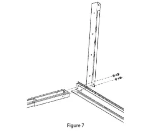
- Place one Top Bracket on the top front side of the Rack. (Figure 6)
- Place a second Top Bracket on the top rear side of the Rack.
- Insert eight M8 Bolts through eight M8 Washers and into the holes in the Top Brackets and the tops of the Vertical Rails. (Figure 7)
- Tighten the M8 Bolts using the 13 mm Wrench.
Install the Leveling Feet
Note: Flip the Rack onto its side to complete this step.
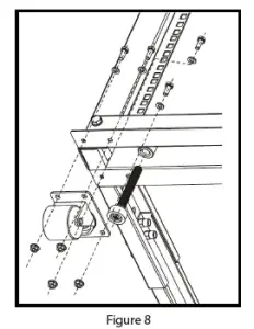
- Insert the four Leveling Feet into the four holes located in the bottom of each Base Bracket.
- Tighten each one of the Leveling Feet by hand, or with a 14 mm Wrench. (Figure 8)
Install the Casters
Notes: Flip the Rack onto its side to complete this step.Two people may be required to complete this step.
- Align the four holes in a Caster with the four holes in the bottom of the Rack.
- Insert four M6 Screws through four M6 Flat Washers and down through the holes in the Rack
- Thread four M6 Flange Nuts onto the M6 Screws. (Figure 8)
- Hold the M6 Screws with the Pliers and tighten the M6 Flange Nuts with the 10 mm Wrench.Note: The M6 Screws will freely rotate if they are not held to prevent rotation.
- Repeat steps 1 to 4 to install the three remaining Casters.
Install the Cable Management Hooks
- Align the Cable Management Hooks with the Cable Mounting Screw Holes along the back of the Rack.
- Insert a Hook Mounting Screw though the Rack and into the Cable Management Hook. (Figure 9)
- Using the Phillips Head Screwdriver, tighten the Hook Mounting Screw, being careful not to over-tighten.]
- Repeat steps 1 to 3 to install the remaining Cable Management Hooks.
Ground the Rack
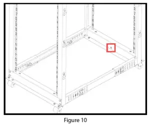
- Insert an M6 Screw through the Grounding Point on the Grounding Wire and into the Ground Hole located on the bottom of the Rack. (Figure 10)
- Run the Grounding Wire under the Rack’s Frame.
- Connect the Grounding Wire to an Earth Ground Connection.
Operation
Adjust the Leveling FeetUnscrew the Levelling Feet by hand and with a 14 mmWrench, until all four Levelling Feet are set to the same height and pressed firmly against the floor.Note: Use a Spirit/Bubble Level to ensure the Rack is level.
Warranty Information
This product is backed by a two-year warranty. For further information on product warranty terms and conditions, please referto www.startech.com/warranty
Limitation of Liability
In no event shall the liability of StarTech.com Ltd. and StarTech.com USA LLP (or their officers, directors, employees or agents) for any damages (whether direct or indirect, special, punitive, incidental, consequential, or otherwise), loss of profits, loss of business, or any pecuniary loss, arising out of or related to the use of the product exceed the actual price paid for the product.Some states do not allow the exclusion or limitation of incidental or consequential damages. If such laws apply, the limitations or exclusions contained in this statement may not apply to you.
Hard-to-find made easy. At StarTech.com, that isn’t a slogan. It’s a promise.
StarTech.com is your one-stop source for every connectivity part you need. From the latest technology to legacy products — and all the parts that bridge the old and new — we can help you find the parts that connect your solutions. We make it easy to locate the parts, and we quickly deliver them wherever they need to go. Just talk to one of our tech advisors or visit our website. You’ll be connected to the products you need in no time. Visit www.startech.com for complete information on all StarTech.com products and to access exclusive resources and time-saving tools. StarTech.com is an ISO 9001 Registered manufacturer of connectivity and technology parts. StarTech.com was founded in 1985 and has operations in the United States, Canada, the United Kingdom and Taiwan servicing a worldwide market.
Reviews
Share your experiences using StarTech.com products, including product applications and setup, what you love about the products, and areas for improvement.
StarTech.com Ltd. StarTech.com LLP StarTech.com Ltd.
 report this ad
45 Artisans Cres. 2500 Creekside Pkwy Unit B, PinnacleLondon, Ontario Lockbourne, Ohio 15 Gowerton Rd., BrackmillsN5V 5E9 43137 Northampton NN4 7BWCanada U.S.A. United Kingdom
Read More About This Manual & Download PDF:
References
StarTech.com Support
当社は、接続、変換、拡張、分離、切換えを行うIT & A / Vプロフェッショナルのためのパーツを製造しています | 日本
Pezzi per computer, cavi, switch KVM, server rack e soluzioni per reti | Italia
StarTech.com | IT Pro\’s Trusted Source for Connectivity Accessories
StarTech.com Warranty Policy
StarTech.com diseña y fabrica una variada gama de componentes para ordenadores, cables, conmutadores KVM, racks para… | España
StarTech.com ontwerpt en produceert een enorme selectie computeronderdelen, kabels, KVM-switches, serverracks en… | Nederland
StarTech.com | IT Pro\’s Trusted Source for Connectivity Accessories
Unsere Produkte dienen IT- und A/V-Profis zum Verbinden, Konvertieren, Erweitern, Splitten und Switchen | Deutschland
StarTech.com conçoit et fabrique une vaste sélection de pièces d’ordinateur, de câbles, de commutateur KVM, de racks… | France
[xyz-ips snippet=”download-snippet”]