![]()
Quick-Start Guide8 Port Unmanaged Industrial-Grade Switch 10/100/1000 Mbps
Product Diagram (IESC1G80UP)
|
Front View |
|
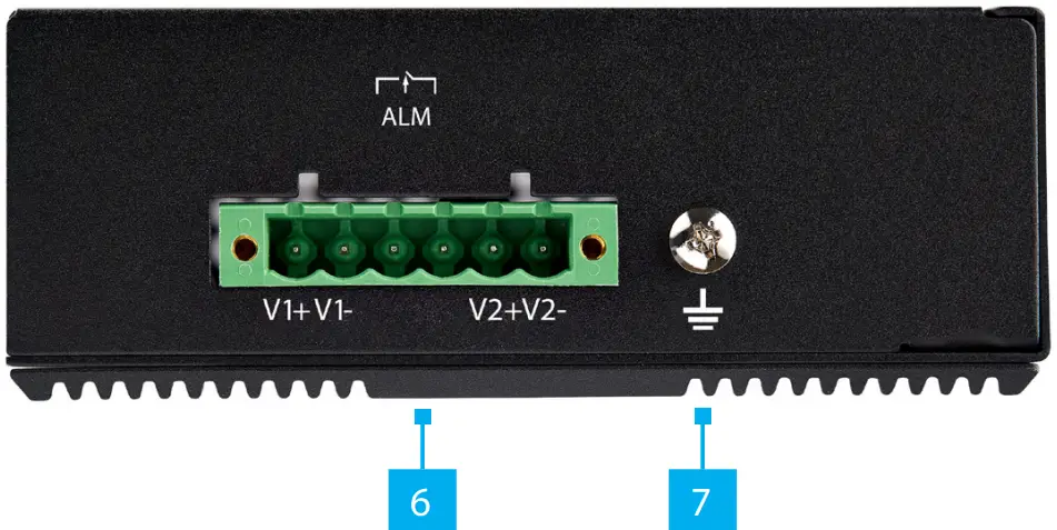
Side View |
 |
|
Component |
Function |
|
| 1 | PoE Ports | • Connect any Network Device to provide an Ethernet Connection to up to 8 Network Devices• Provide a PoE Connection to 8 Devices• Maximum PoE power budget is 30W per port up to a total overall power budget of 200W |
| 2 | ERR LED Indicator | • Color – Amber• On – Either PW1 or PW2 is connected• Off – Both PW1 and PW2 are connected |
| 3 | PW2 LED Indicator | • Color – Green• On – when PW2+ and PW2- are connected• Off- when PW2+ and PW2- are not connected |
| 4 | PW1 LED Indicator | • Color – Green• On – when PW1+ and PW1– are connected• Off- when PW1+ and PW1- are not connected |
| 5 | PoE LED Indicators | • Indicates the link and PoE Powered Device (PD) status of each PoE Port LNK(Green)• On – Network connection detected• Off – Network connection not detected PoE (Amber)• On – PoE is detected• Off – PoE is not detected |
| 6 | Terminal Block Power
Input Port |
• Provides power to the PoE Ports• Supported power input voltage range is 48-56V |
| 7 | Grounding Screw | • Attach a Grounding Wire to protect Network Equipment |
Requirements
For the latest requirements, please visit www.startech.com/IESC1G80UP.
- DC Power Supply x 1 (maximum of two)
- PoE Powered Device x (up to) 8
- RJ45 Terminated UTP/STP Cat 5e (or better) Network Cable (sold separately) x 8
- Earth Ground Connection x 1
- Grounding Wire x 1
- (Optional – for power) Flat Head Screwdriver x 1
- (Optional) #2 Phillips Head Screwdriver x 1
- (Optional) Screws for Wall Mounting x 2
Installation
Grounding the Switch
- Using the Phillips Head Screwdriver loosen the Grounding Screw on the Switch.
- Attach the Grounding Wire to the Grounding Screw.
- Tighten the Grounding Screw.
- Connect the other end of the Grounding Wire to the Earth Ground Connection.
Connect the Power SourceConnecting and installing the Terminal Block must be completed by a licensed Electrician.Notes: Make sure that you turn off the power source before connecting the power wire to the Terminal Block.Do not exceed the recommended voltage as it may result in personal or product damage.This unit includes an additional relay circuit. When two Power Sources are connected the relay stays in Open Mode. If only one Power Source is connected the relayswitches to Short Mode.Connect the Power Wires from a DC Power Source (48 – 56V DC) to the Terminal Block Connectors on the Switch. The terminals are marked on the exterior of the Switch (connect the Positive Wire to V+ and the Negative Wire to V-).• Secure the Wires by tightening the Screws in the Terminal Block with a Flat Head Screwdriver
Connecting the Switch
- Connect a Network Cable to the Network Device and to any one of the PoE Ports on the Switch.
- Connect a Network Cable to a PoE PD and to any one of the seven remaining PoE Ports on the Switch. Repeat this step up to six times.
(Optional) Mounting the SwitchWall Mounting
- Align the holes in the Wall Mount Brackets with the holes in the back of the Switch.
- Insert two Phillips Head Screws through each Wall Mount Brackets and into the Switch.
- Tighten the Phillips Head Screws using a Phillips Head Screwdriver (sold separately).Note: Be careful not to over-tighten the Screws.
- Insert two Screws (sold separately) through the Wall Mount Brackets and into the Mounting Surface.
- Tighten the Screws using the appropriate Screwdriver.
DIN Rail Mounting
- Align the holes in the DIN Rail Bracket with the holes in the back of the Switch.
- Insert three Phillips Head Screws through the DIN Rail Bracket and into the Switch.
- Tighten the Phillips Head Screws using a Phillips Head Screwdriver.Note: Be careful not to over-tighten the Screws.
- Hang the top of the DIN Rail Bracket (the section with the two metal clips) onto a Top Hat style DIN Rail.
- Press the DIN Rail Bracket down and forward to lock the bottom section onto the DIN Rail.
FCC Compliance Statement
This equipment has been tested and found to comply with the limits for a Class A digital device, pursuant to Part 15 of the FCC rules. These limits are designed to provide reasonable protection against harmful interference when the equipment is operated in a commercial environment. This equipment generates, uses and can radiate radio frequency energy and, if not installed and used in accordance with the instruction manual, may cause harmful interference to radio communications. Operation ofthis equipment in a residential area is likely to cause harmful interference in which case the user will be required to correct the interference at his own expense.This device complies with part 15 of the FCC Rules. Operation is subject to the following two conditions: (1) This device may not cause harmful interference, and (2) this device must accept any interference received, including interference that may cause undesired operation.Changes or modifications not expressly approved by StarTech.com could void the user’s authority to operate the equipment.Industry Canada StatementThis Class A digital apparatus complies with Canadian ICES-003.CAN ICES-3 (A)/NMB-3(A)This device complies with Industry Canada licence-exempt RSS standard(s). Operation is subject to the following two conditions:(1) This device may not cause interference, and (2) This device must accept any interference, including interference that may cause undesired operation of the device.Use of Trademarks, Registered Trademarks, and other Protected Names and SymbolsThis manual may make reference to trademarks, registered trademarks, and other protected names and/or symbols of third-party companies not related in any way to StarTech.com. Where they occur these references are for illustrative purposes only and do not represent an endorsement of a product or service by StarTech.com, or anendorsement of the product(s) to which this manual applies by the third-party company in question. StarTech.com hereby acknowledges that all trademarks, registered trademarks, service marks, and other protected names and/or symbols contained in this manual and related documents are the property of their respective holders.PHILLIPS® is a registered trademark of Phillips Screw Company in the United States or other countries.
Warranty Information
 report this ad
This product is backed by a two-year warranty.For further information on product warranty terms and conditions, please refer to www.startech.com/warranty.
Limitation of Liability
In no event shall the liability of StarTech.com Ltd. and StarTech.com USA LLP (or their officers, directors, employees or agents) for any damages (whether direct or indirect, special, punitive, incidental, consequential, or otherwise), loss of profits,loss of business, or any pecuniary loss, arising out of or related to the use of the product exceed the actual price paid for the product. Some states do not allow the exclusion or limitation of incidental or consequential damages. If such laws apply, the limitations or exclusions contained in this statement may not apply to you.
Safety Measures
- If the product has an exposed circuit board, do not touch the product under power.
| StarTech.com Ltd.45 Artisans CresLondon, OntarioN5V 5E9Canada | StarTech.com LLP2500 CreeksideParkwayLockbourne, Ohio43137U.S.A. | StarTech.com Ltd.Unit B, Pinnacle 15Gowerton Rd,BrackmillsNorthamptonNN4 7BWUnited Kingdom | FR: startech.com/frDE: startech.com/deES: startech.com/esNL: startech.com/nlIT: startech.com/itJP: startech.com/ |
References
[xyz-ips snippet=”download-snippet”]