![]() Industrial RJ45 to Open SFP Mini PoE Media Converter1000 Mbps (1G)60W
Industrial RJ45 to Open SFP Mini PoE Media Converter1000 Mbps (1G)60W
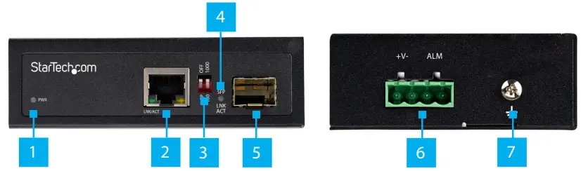
Product Diagram (IMC1GSFP60W)
|
NO |
Component |
Function |
| 1 | PWR LED |
|
| 2 | RJ45 Port |
|
| 3 | DIP Switch | DIP1: This switch is currently not in use.DIP 2:
|
| 4 | SFP LED |
|
| 5 | SFP Slot |
|
| 6 | 4-Pin Terminal Block |
|
| 7 | Ground Screw |
|
Requirements
For the latest requirements, please visit www.startech.com/IMC1GSFP6OW
- Network Equipment (e.g. Router, Network Switch) x 1
- MSA-Compliant 100/1000BASE-X SFP Transceiver Module x 1
- RJ45 Terminated UTP/STP CAT5e (or better) Network Cable x 1
- Terminated Fiber Optic Cable (dependent on SFP Module) x 1
- DC Power Source x 1
- Small Flat Head Screwdriver x 1
- Phillips Head Screwdriver x 1
- Alarm or Warning Circuit x 1
Powering the Media Converter
Connecting and installing the 4-Wire Terminal Connector must be completed by a licensed Electrician.Notes: Make sure that you turn off the power source before connecting the power wire to the Media Converter.Do not exceed the recommended power source voltage as it may result in personal or product damage.
- Using a Small Flat Head Screwdriver, loosen the two screws (+V-) on the 4-Wire Terminal Connector (included).
- Connect the Power Wires from a DC Power Source (48 – 56V DC), or the provided Barrel Power Connector Adapter to the proper Terminal Block Connectors on the Media Converter. The terminals are marked on the Media Converter’s Casing (connect the positive wire to V+ and the negative wire to V-).
- (Optional) Using a Small Flat Head Screwdriver, loosen the two screws (ALM) on the 4-Wire Terminal Connector.
- (Optional) Connect the Relay Wires from an Alarm or Warning Circuit to the 2 ALM Relay Pins on the Terminal Block Connector.
- Tighten the four screws on the 4-Wire Terminal Connector.
- Insert the 4-Wire Terminal Connector in the 4-Wire Terminal Block on the Media Converter.
- Using a Phillips Head Screwdriver, loosen the Ground Screw on the Media
- Connect the Ground Wire from an Earth Ground Connection to the Ground Screw on the Media Converter.
- Using the Small Flat Head Screwdriver, tighten the Ground Screw to secure the Grounding Wire to the Media Converter.(Optional) Barrel Connector• Connect a Type N (OD: 5.5 mm, ID: 2.5 mm) Barrel Connector from a UniversalPower Adapter to the Terminal Block to Barrel Power Connector Adapter.
Connecting the Media Converter
- Connect a CAT5e/6 Cable to the RJ45 Port on the Media Converter and the other end to an RJ45 port on a Network Device.
- Insert an MSA-Compliant SFP Transceiver Module (sold separately) into the SFP Slot on the Media Converter.
- Remove the Dust Cover from the SFP Module and connect the appropriate cable (CAT5e/6 or Fiber).
Mounting
DIN Rail Mounting
- Align the DIN Rail Brackets (x 1) with the Mounting Holes (x 4) on the side of the Media Converter.
- Insert the Mounting Screws (x 3) through the DIN Rail Bracket and into the Media
- Using a Phillips Head Screwdriver, tighten the Mounting Screws. Be careful not to over-tighten the Mounting Screws.
- Clip the DIN Rail Bracket onto a DIN Rail, securing the Media Converter.
Wall Mounting
It is recommended that you use Wall Studs when wall mounting the Media Converter.
- Align the Mounting Brackets (x 2) with the Mounting Holes (x 4) on the side of the Media Converter.
- Insert the Mounting Screws (x 4) through each of the Mounting Brackets and into the Media Converter.
- Align the Media Converter on the wall in the position you want to mount the Media Converter.
- Using a Writing Utensil, mark off both Mounting Holes on the Media Converter.
- Using a level, draw a line connecting the two Mounting Holes, making sure that the line is level.
- Align the Mounting Holes on the Media Converter with the Mounting Hole
- Insert the Mounting Screws (x 2) through the Mounting Holes on the Media Converter and into the
- Using a Phillips Head Screwdriver, tighten the Mounting Screws until the Media Converter is securely fastened to the Wall.
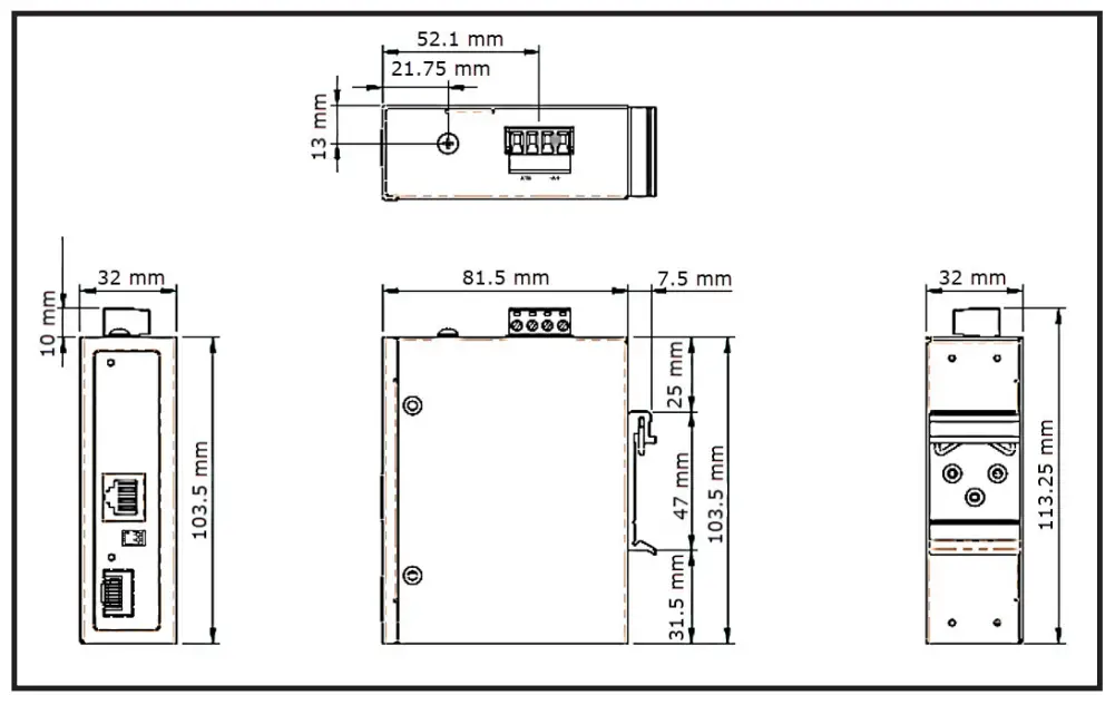
Product Dimensions
FCC Compliance Statement
This equipment has been tested and found to comply with the limits for a Class A digital device, pursuant to Part 15 of the FCC rules. These limits are designed to provide reasonable protection against harmful interference when the equipment is operated in a commercial environment. This equipment generates, uses, and can radiate radio frequency energy and, if not installed and used in accordance with the instruction manual, may cause harmful interference to radio communications. Operation of this equipment in a residential area is likely to cause harmful interference in which case the user will be required to correct the interference at his own expense.This device complies with part 15 of the FCC Rules. Operation is subject to the following two conditions: (1) This device may not cause harmful interference, and (2) this device must accept any interference received, including interference that may cause undesired operation.Changes or modifications not expressly approved by StarTech.com could void the user’s authority to operate the equipment.Industry Canada StatementThis Class A digital apparatus complies with Canadian ICES-003.CAN ICES-3 (A)/NMB-3(A)Use of Trademarks, Registered Trademarks, and other Protected Names and SymbolsThis manual may make reference to trademarks, registered trademarks, and other protected names and/or symbols of third-party companies not related in any way to StarTech.com. Where they occur these references are for illustrative purposes only and do not represent an endorsement of a product or service by StarTech.com, or anendorsement of the product(s) to which this manual applies by the third-party company in question. StarTech.com hereby acknowledges that all trademarks, registered trademarks, service marks, and other protected names and/or symbols contained in this manual and related documents are the property of their respective holders.
Warranty Information
This product is backed by a two-year warranty.For further information on product warranty terms and conditions, please refer to www.startech.com/warranty.Limitation of LiabilityIn no event shall the liability of StarTech.com Ltd. and StarTech.com USA LLP (or their officers, directors, employees, or agents) for any damages (whether direct or indirect, special, punitive, incidental, consequential, or otherwise), loss of profits, loss of business, or any pecuniary loss, arising out of or related to the use of the product exceed the actual price paid for the product.Some states do not allow the exclusion or limitation of incidental or consequential damages. If such laws apply, the limitations or exclusions contained in this statement may not apply to you.
| StarTech.com Ltd.45 Artisans CresLondon, Ontario N5V 5E9Canada | StarTech.com LLP2500 CreeksideParkwyLockbourne, Ohio 43137The U.S.A. | StarTech.com Ltd.Unit B, Pinnacle 15Gowerton Rd, BrackmillsNorthampton NN4 7BWUnited Kingdom | FR: startech.com/frDE: startech.com/deES: startech.com/esNL: startech.com/nlIT: startech.com/itJP: startech.com/jp |
 report this ad
To view manuals, FAQs, videos, drivers, downloads, technical drawings, and more, visit www.startech.com/support.
![]() www.startech.comManual Revision:June 2, 20202:48 PM
www.startech.comManual Revision:June 2, 20202:48 PM
References
[xyz-ips snippet=”download-snippet”]