![]()
30W Industrial – Grade Hardened PoE Injector | 1G (1000 Mbps)
Product Diagram (POEINJ30W)
![]()
| Component | Function | |
| 1 | Power LEDs | • Green: A Power Source is detected.• Off: A Power Source is not detected. |
| 2 | Mode A LED | • Mode A (Green): Indicates that the PoE Injector is providing power.• Off: Indicates that the PoE Injector is in idle mode. |
| 3 | PoE Out Port | • Connect a PoE PD Device to the PoE Injector. |
| 4 | Data Port | • Connect a Network Switch to the PoE Injector. |
| 5 | 4-Pin Terminal Block V1 and V2 | • Connect an external DC Power Source (48-56V DC Input) to the PoE Injector. |
| 6 | Ground Screw | • Connect a ground connection to the Ground Screw when connecting a DC Power Source to the PoE Injector. |
Requirements
For the latest requirements, please visit www.startech.com/POEINJ30W
- Small Flat Head Screwdriver x 1
- Writing Utensil x 1
- PoE PD Device x 1
- Network Switch x 1
- DC Power Source or Universal Power Adapter with Type N (OD: 5.5 mm, ID: 2.5 mm) Barrel Connector x 1
- (Optional) Phillips® Head Screwdriver x 1
- RJ45 Terminated UTP/STP Cat 5e (or better) Network Cable x 2
Powering the PoE Injector
Terminal Block
Connecting and installing the 4-Wire Terminal Connector must be completed by a licensed Electrician.Notes: Make sure that you turn off the power source before connecting the power wire to the PoE Injector.Do not exceed the recommend power source voltage as it may result in personal or product damage.
- Using a Small Flat Head Screwdriver, loosen the two screws, either V1 or V2 on the 4-Wire Terminal Connector (included).
- Connect the Power Wires from a DC Power Source (48 – 56V DC), or the provided Barrel Power Connector Adapter, to the proper Terminal Block Connectors (the terminals are marked on the PoE Injector’s Casing). Connect the positive wire to V+ and the negative wire to V-.
- Tighten the two screws on the 4-Wire Terminal Connector.
- Insert the 4-Wire Terminal Connector in the 4-Wire Terminal Block on the PoE Injector.
- To connect a second Power Source to the PoE Injector, repeat steps 1 – 4.
- Using a Phillips Head Screwdriver, loosen the Ground Screw on the PoE Injector.
- Connect the Ground Wire from a DC Power Source to the Ground Screw on the PoE Injector.
- Using the Phillips Head Screwdriver, tighten the Ground Screw to secure the Grounding Wire to the PoE Injector.
(Optional) Barrel Connector
- Connect a Type N (OD: 5.5 mm, ID: 2.5 mm) Barrel Connector from a UniversalPower Adapter to the Terminal Block to Barrel Power Connector Adapter.
Connecting the PoE Injector
Note: Make sure the total length of the CATSe/6 Cable connecting the PD Device to the PoE Injector and the CATSe/6 Cable connecting the PoE Injector to the Remote Switch does not exceed 100 meters in total length.
- Connect a CATSe/6 Cable to the PoE Out Port on the PoE Injector and the other end to an RJ45 port on a PoE PD Device (e.g. security camera, etc.).
- Connect a CAT5e/6 Cable to the Data Port on the PoE Injector and the other end to an RJ45 port on a Network Switch.
Mounting
DIN Rail Mounting
- Align the DIN Rail Brackets (x 1) with the Mounting Holes (x 4) on the side of the PoE Injector.
- Insert the Mounting Screws (x 3) through the DIN Rail Bracket and into the PoE Injector.
- Using a Phillips Head Screwdriver, tighten the Mounting Screws. Be careful not to over-tighten the Mounting Screws.
- Clip the DIN Rail Bracket onto a DIN Rail, securing the PoE Injector.Wall Mounting
It is recommended that you use Wall Studs when wall mounting the PoE Injector.
- Align the Mounting Brackets (x 2) with the Mounting Holes (x 4) on the side of the PoE Injector.
- Insert the Mounting Screws (x 4) through each of the Mounting Brackets and into the PoE Injector.
- Align the PoE Injector on the wall in the position you want to mount the PoE Injector.
- Using a Writing Utensil, mark off both Mounting Holes on the PoE Injector.
- Using a Level, draw a line connecting the two Mounting Holes, making sure that the line is level.
- Align the Mounting Holes on the PoE Injector with the Mounting Hole Marks.
- Insert the Mounting Screws (x 2) through the Mounting Holes on the PoE Injector and into the Wall.
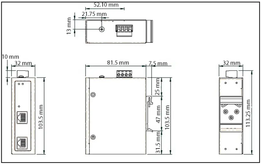
- Using a Phillips Head Screwdriver, tighten the Mounting Screws until the PoE Injector is securely fasten to the Wall.Product Dimensions

FCC Compliance Statement
This equipment has been tested and found to comply with the limits for a Class A digital device, pursuant to Part 15 of the FCC rules. These limits are designed to provide reasonable protection against harmful interference when the equipment is operated in a commercial environment. This equipment generates, uses, and can radiate radio frequency energy and, if not installed and used in accordance with the instruction manual, may cause harmful interference to radio communications. Operation of this equipment in a residential area is likely to cause harmful interference in which case the user will be required to correct the interference at his own expense.This device complies with part 15 of the FCC Rules. Operation is subject to the following two conditions: (1) This device may not cause harmful interference, and (2) this device must accept any interference received, including interference that may cause undesired operation.Changes or modifications not expressly approved by StarTech.com could void the user’s authority to operate the equipment.
Industry Canada Statement
This Class A digital apparatus complies with Canadian ICES-003.Cet appareil numérique de la classe [A] est conforme à la norme NMB-003 du Canada.CAN ICES-3 (A)/NMB-3(A)
Use of Trademarks, Registered Trademarks, and other Protected Names and Symbols
This manual may make reference to trademarks, registered trademarks, and other protected names and/or symbols of thirdparty companies not related in any way to StarTech.com. Where they occur these references are for illustrative purposes only and do not represent an endorsement of a product or service by StarTech.com, or an endorsement of the product(s) to which this manual applies by the third-party company in question. StarTech.com hereby acknowledges that all trademarks, registered trademarks, service marks, and other protected names and/or symbols contained in this manual and related documents are the property of their respective holders.
Warranty Information
This product is backed by a two-year warranty.For further information on product warranty terms and conditions, please refer to www.startech.com/warranty.
Limitation of Liability
In no event shall the liability of StarTech.com Ltd. and StarTech.com USA LLP (or their officers, directors, employees or agents) for any damages (whether direct or indirect, special, punitive, incidental, consequential, or otherwise), loss of profits, loss of business, or any pecuniary loss, arising out of or related to the use of the product exceed the actual price paid for the product. Some states do not allow the exclusion or limitation of incidental or consequential damages. If such laws apply, the limitationsor exclusions contained in this statement may not apply to you.
Safety Measures
• If product has an exposed circuit board, do not touch the product under power.
| StarTech.com Ltd.45 Artisans CresLondon, OntarioN5V 5E9Canada | StarTech.com LLP2500 CreeksideParkwy Lockbourne,Ohio 43137U.S.A. | StarTech.com Ltd.Unit B, Pinnacle 15Gowerton Rd, BrackmillsNorthamptonNN4 7BWUnited Kingdom | FR: startech.com/frDE: startech.com/deES: startech.com/esNL: startech.com/nlIT: startech.com/itJP: startech.com/jp |
 report this ad
To view manuals, FAQs, videos, drivers, downloads, technical drawings, and more, visit www.startech.com/support.
References
[xyz-ips snippet=”download-snippet”]