![]()
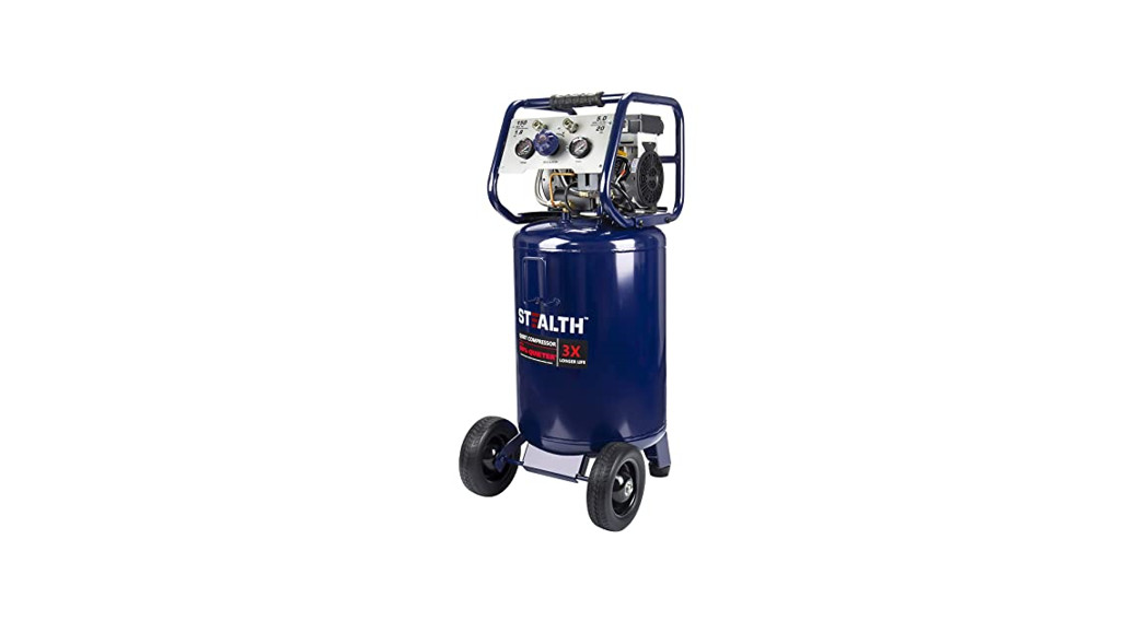
Product Model: SAQ-12018Item# 3332081OPERATOR’S MANUAL20 Gallon Air Compressor

 CAUTION:To Reduce The Risk Of Injury, User Mu. Read And Understand Opf©s Manual. Save These Instructions For Future Reference. Toll-Free Helpline: 1-888-899-0146
TECHNICAL SPECIFICATIONS
| PRODUCT NUMBER | 3332081 |
| RUNNING HORSEPOWER | 1.8 |
| TANK SIZE(TOTAL) | 20 U.S. Gallons(75L) |
| AIR | 6.0↑ |
| AIR DELIVERY(CFM*)@90PSI | 5.0↑ |
| CUT-IN PRESSURE(PSI) | 120 |
| CUT-OUT PRESSURE(PSI) | 150 |
| PUMP DESIGN | OIL-FREE |
| MOTOR | INDUCTION |
| POWER | 120V, 601-12, 12A |
| WEIGHT | 121Ibs(55kg) |
| POWER CORD | SJT 16 AWG / 72″(1.83m) |
*CFM Cubic Feet per Minute*This compressor is rated in accordance with ISO 1217, displacement compressors acceptance tests.![]() SAVE THESE INSTRUCTIONSThis manual contains important safety and operating instructions. Read all instructions and follow them with the use of this product.
SAVE THESE INSTRUCTIONSThis manual contains important safety and operating instructions. Read all instructions and follow them with the use of this product.
SAFETY GUIDELINES
Important Safety InformationThe manufacturer cannot possibly anticipate every possible circumstance that might involve a hazard. The warnings in this manual and the tags and decals affixed to the unit are, therefore, not all-inclusive. If you use a procedure, work method, or operating technique that the manufacturer does not specifically recommend, you must satisfy yourself that it is safe for you and others You must also make sure that the procedure, work method, or operating technique that you choose does not render the compressor unsafe.Safety Symbols and Meanings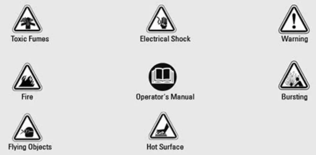 The safety alert symbol indicates a potential hazard to personal injury. A signal word (DANGER, WARNING, or CAUTION) is used with the alert symbol to designate a degree or level of hazard seriousness. A safety symbol may be used to represent the type of hazard The signal word NOTICE is used to address practices not related to personal injury.
![]() DANGER indicates a hazard that, if not avoided, will result in death or serious injury.
DANGER indicates a hazard that, if not avoided, will result in death or serious injury.![]() WARNING indicates a hazard that, if not avoided, could result in death or serious injury.
WARNING indicates a hazard that, if not avoided, could result in death or serious injury.![]() CAUTION indicates a hazard that, if not avoided, could result in minor or moderate injury.Notice address practices not related to personal injury
CAUTION indicates a hazard that, if not avoided, could result in minor or moderate injury.Notice address practices not related to personal injury
SAFETY INFORMATION
![]() DO NOT OPERATE THIS UNIT UNTIL YOU READ AND UNDERSTAND THIS INSTRUCTION MANUAL FOR SAFETY, OPERATION, AND MAINTENANCE INSTRUCTIONS.
DO NOT OPERATE THIS UNIT UNTIL YOU READ AND UNDERSTAND THIS INSTRUCTION MANUAL FOR SAFETY, OPERATION, AND MAINTENANCE INSTRUCTIONS.![]() WARNING
WARNING Risk of fire caused by sparks from motor and pressure switches could result in death or serious injury. Do not operate compressor near flammable gas or vapor. Never store flammable liquids or gases in the vicinity of the compressor.
![]() High-pressure air could result in death or serious injury.
High-pressure air could result in death or serious injury.
- Never operate above the maximum operating pressure of the spray gun or tool. Drain water from the tank after each use Do not weld or repair tank after each use. Do not weld or repair the tank.
- Do not operate with the pressure switch or safety valve set above maximum allowable working pressure.
 Hot compressors surfaces could result in serious injury. Allow the compressor to cool before touching.
 Inhalation hazard. Using a compressor to supply breathing air could result in death or serious injury Do not use a compressor to supply breathing air.
 Risk of fire could result in death or serious injury
- Do not spray flammable materials in the vicinity of any flame or ignition sources including the compressor unit.
- Do not restrict compressor ventilation openings or place objects against or on top of compressor Operate compressor only in a clean, dry, well-ventilated area.
- Do not operate unattended. Always turn off and unplug the unit when not in use.
 Risk of serious eye injury Always wear ANSI 787 1 approved safety goggles when using air compressor Do not spray any part of the body
 Shock risk could result in death or serious injury. Only connect the compressor to a properly grounded receptacle. KEEP CHILDREN AWAY FROM THE AIR COMPRESSOR AT ALL TIMES.
![]() Dust can be created when cutting, sanding, drilling or grinding materials such as wood, paint, metal, concrete, cement, or another masonry. To reduce your exposure to these chemicals, work in a well-ventilated area and ALWAYS wear approved safety equipment
Dust can be created when cutting, sanding, drilling or grinding materials such as wood, paint, metal, concrete, cement, or another masonry. To reduce your exposure to these chemicals, work in a well-ventilated area and ALWAYS wear approved safety equipment![]() WARNING: This product can expose you to chemicals including lead, which is known to the State of California to cause cancer, birth defects, or other reproductive harm. For more information go to mww.P65Warnings.ca.gov.
WARNING: This product can expose you to chemicals including lead, which is known to the State of California to cause cancer, birth defects, or other reproductive harm. For more information go to mww.P65Warnings.ca.gov.
KEY PARTS DIAGRAM
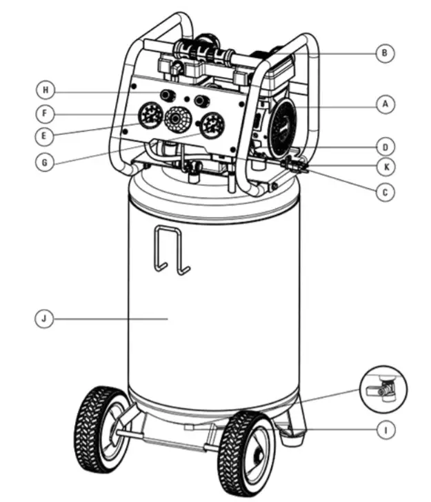
| A. | Electrical Motor | G | Outlet Pressure Gauge |
| B. | Air Compressor Pump | H. | Quick Coupler |
| C | Safety Valve | I. | Drain Valve |
| D. | ON/OFF Switch | J. | Air Tank |
| E | Air Pressure Regulator | K. | Power Cord |
| F | Tank Pressure Gauge |
PARTS DESCRIPTION
A.Electnc MotorThe motor is used to power the pump It is equipped with a thermal overload protector If the motor overheats for any reason, the thermal overload protector will shut it down in order to prevent the motor from being damaged.B. Air Compressor PumpThe pump compresses the air and discharges it into the tank via the piston that moves up and down in the cylinder.C. Safety ValveThis valve is used to prevent the compressor from building too much pressure. If the pressure reaches the preset level of the motor, it will automatically pop open. You can also pull the ring on the valve to open manuallyD. ON/OFF Switch This switch turns on the compressor and is operated manually When in the ON position, it allows the compressor to start up or shut down automatically, without warning, upon air demand.ALWAYS set this switch to OFF when the compressor is not being used and before unplugging the compressor.E. Air Pressure RegulatorThe regulator is used to adjust the pressure inside the line to the tool that is being used. Turn the knob clockwise to increase the pressure and counter-clockwise to decrease the pressure.F. Tank Pressure GaugeThe gauge measures the pressure level of the air that is stored in the tank It cannot be adjusted by the operator and it does not indicate the pressure inside the lineG. Outlet Pressure GaugeThe gauge measures the regulated outlet pressureH. Quick CouplerThe outlet is connected to a quick connector which is connecting to the air hose.I. Air Tank Drain ValveThe drain valve is used to remove moisture from the air tank after the compressor is shut off.K. Power CordThis product is for use on a nominal 120-volt circuit and should be grounded A cord with a grounding plug as illustrated must be used. Make sure that the product is connected to an outlet that has the same configuration as the plug (see Figure 1). No adapter should be used with this product. Check with a licensed electrician if the grounding instructions are not understood or there is doubt as to whether the product is properly grounded. Do not modify the plug provided. If it will not fit the outlet, have the proper outlet installed by a licensed electrician.![]() DANGER Improper installation of the grounding plug will result in a risk of electric shock If repair or replacement of the cord or plug is necessary, do not connect the grounding wire to either flat blade terminal The grounding wire is in the green outer surface.
DANGER Improper installation of the grounding plug will result in a risk of electric shock If repair or replacement of the cord or plug is necessary, do not connect the grounding wire to either flat blade terminal The grounding wire is in the green outer surface.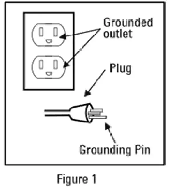
ASSEMBLY INSTRUCTIONS
- Unpack the air compressor unit Inspect the unit for damaged. If the unit has been damaged, contact the retailer immediately.
- Check the air compressor’s identification label to ensure that you have purchased the intended model and that it has the required pressure rating for its intended use.
The carton should contain:
- Air compressor
- Owner’s manual
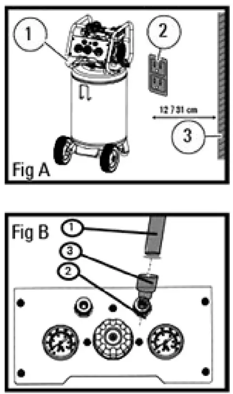
Positioning of the air compressor
- Position the air compressor( 1) near an electrical outlet (211 fig A)
- The compressor must be at least 12′-131 cm) from any wall ( 3) or obstruction, in a clean, well-ventilated area to ensure sufficient airflow and cooling figA).
- Place the air compressor on the floor or a hard. level surface. The air compressor must be level to ensure proper drainage of the moisture in the tank
Connect the air hose to the compressor
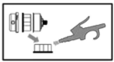
- Connect the air hose (1) to the compressor’s air outlet ( 2) with the quick connector (31( fig B).
Note: Air hose and quick connector are not provided, need to be purchased separately. Apply plumber’s tape on all the threads to prevent air leakage.
![]() WARNINGHigh-pressure air could result in death or serious injury Never operate above the maximum operating pressure of the spray gun or tool WARNINGHot compressor surfaces could result in serious injury Allow the compressor to cool before touching.NoticeIf the pump has been transported or turned upside down (even partially), allow the pump to sit in a normal, upright position for approximately 10 minutes before starting WARNINGRisk of serious eye injury from moisture and debris. Always wear ANSI Z87 1 safety goggles when opening the drain valve.
WARNINGHigh-pressure air could result in death or serious injury Never operate above the maximum operating pressure of the spray gun or tool WARNINGHot compressor surfaces could result in serious injury Allow the compressor to cool before touching.NoticeIf the pump has been transported or turned upside down (even partially), allow the pump to sit in a normal, upright position for approximately 10 minutes before starting WARNINGRisk of serious eye injury from moisture and debris. Always wear ANSI Z87 1 safety goggles when opening the drain valve.![]() WARNINGHigh-pressure air could result in death or serious injury Shut off unit, unplug and release air pressure prior to servicing
WARNINGHigh-pressure air could result in death or serious injury Shut off unit, unplug and release air pressure prior to servicing![]() CAUTIONHigh-pressure air containing water condensation could result in minor or moderate injury. Do not spray at any person.
CAUTIONHigh-pressure air containing water condensation could result in minor or moderate injury. Do not spray at any person.
OPERATING INSTRUCTIONS
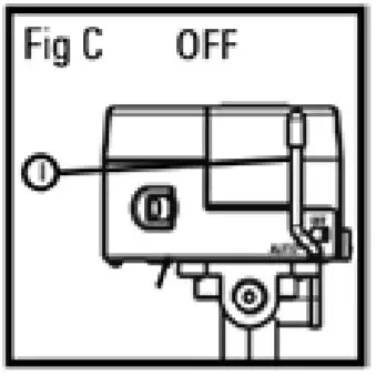
Break in the pump
- Set the ON/OFF switch (1) to the OFF position (fig C).

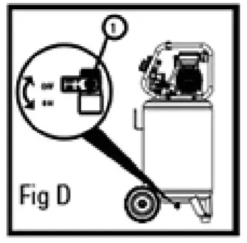
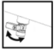
- Open tank drain valve (1) by turning it counter-clockwise to permit the air to escape and prevent air pressure build-up in the air tank during the break-in period (fig D).
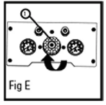
- Turn the air pressure regulator knob (1) clockwise until it stops (fig E).
- Plugin the power cord• Use a dedicated circuit The compressor will use the full capacity of a typical 15A household circuit. If any other electrical devices are drawing from the compressor’s circuit, the air compressor may fail to start voltage or an overloaded circuit can result in sluggish starting that causes the motor overload protection system or circuit breaker to trip, especially in cold conditions.• Disconnect the power cord only after the break-in process has been completed, otherwise, the motor might get damaged.
- Set the ON/OFF switch (1) to the ON position The compressor will start running the compressor for 30 minutes. If it fails, turn it off immediately and call the toll-free helpline at 1-888-899.0146 Please note that breaking-in the unit is only required prior to first use( fig F)
- After 30 minutes, turn off the ON/OFF switch.
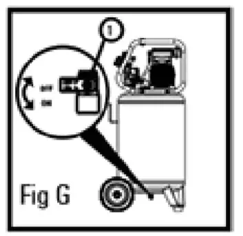
- Close the tank drain valve (1) by turning it clockwise ( fig G)
- Set the ON/OFF switch to the ON position. The air receiver will fill to ‘cut-our pressure and then the compressor’s motor will stop The compressor is now ready for use.

Before each start-up
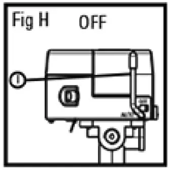
- Set the ON/OFF switch (1) to the OFF position (fig H).
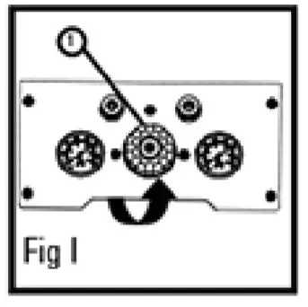
- Turn the air pressure regulator knob (1) counterclockwise until it stops(fig I)
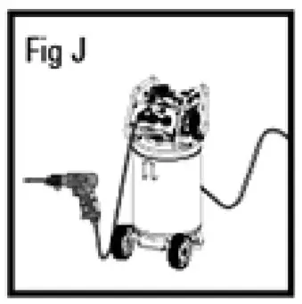
- Attach hose and accessories (fig J) (Hose and accessories need to be purchased separately )
How to start
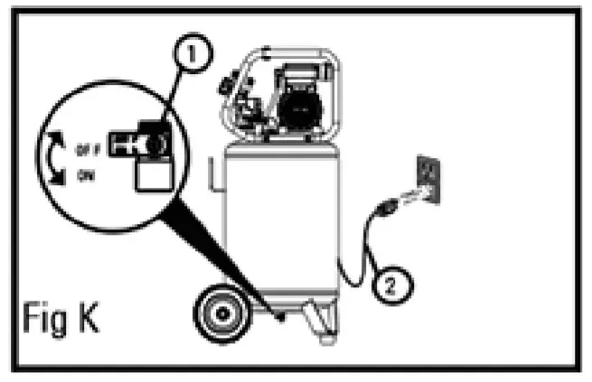
- Close the tank drain valve (1)(fig K).
- Plug-in the power cord(2)(fig H)
- Set the ON/OFF switch to the ON position and allow the tank pressure to build Motor will stop when tank pressure reaches cut-out pressure.
- Turn the air pressure regulator knob clockwise until the desired pressure is reached.
- The compressor is ready for use.
How to shut down
- Set the ON/OFF switch (1 ) to the OFF position.
- Unplug the power cord (2)
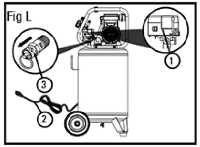
- Reduce the pressure in the tank through the outlet hose. Pulling the safety valve ring (3) and keeping it open will also reduce the pressure in the tank (fig L).
- Set the tank drain valve (1)(tig K) to ON to ensure the tank is drained.
MAINTENANCE
| ITEM | DESCRIPTION / REASON | SERVICE INTERVAL |
| Drain the tank | Through the normal operation of your air compressor, condensation of water will accumulate in the tank. To prevent corrosion of the tank from the inside, condensation must be drained at the end of every workday. Be sure to wear protective goggles. Relieve the air pressure in the system then opens the drain valve on the bottom of the tank to drain. Under cold conditions, it is especially important to drain the tank after each use to reduce the chance of problems resulting from the freezing of condensation water.NOTE: Refer to instructions on how to drain the tank (page 11). | Daily |
| Chock the valve | Pull the safety valve daily to ensure that it is operating properly and to clear the valve of any possible obstructions. | Daily |
| Test for leaks | Check that all connections are tight Small leaks in the tank, hoses, connections or transfer tubes will substantially reduce the air compressor and tool performance. Spray a small amount of soapy water around the area of suspected leaks with a spray bottle. If bubbles appear, repair, replace or reseal the faulty componentDo not over-tighten any connections. | Monthly |
| Clean the air filter | A dirty air filter will reduce air compressor performance and life. To avoid contaminating the pump, the filter should be cleaned frequently and replaced on a regular basis. Clean the cartridge filter by blowing on it with a blowgun (page 11). | Weekly |
| Storage | Before storing the air compressor•Drain tank (page 11).•Use an air blow gun to clean all dust and debris from the compressor•Disconnect and wind up the power cord.•Clean the ventilation openings on the motor enclosure with a damp cloth.•Drain all moisture from the tank.•Pull the pressure safety valve to release all pressure from the tank. i•WARNING: Storage covers could cause a fire resulting in death or serious injury. –Do not place a storage cover over a hot air compressor.Let equipment cool for a sufficient time before placing the cover on the equipment.•Store the air compressor in a clean and dry location.•In cold weather, store the compressor in a warm building when it is not in use. This will reduce problems related to starting the motor and the freezing of water condensation. |
Prior to storing |
Check Safety ValveBefore starting the compressor, pull the ring on the safety valve to make sure that the safety valve operates freely. If the valve is stuck or does not operate smoothly, contact a trained service technician.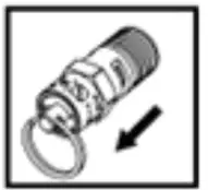 How To Drain Tank
- Set the ON/OFF switch to the 0 (OFF) position
- Unplug the power cord.
- Turn air pressure regulator knob counter-clockwise to set the outlet pressure to zero
- Pull and hold the ring on the safety valve, allowing air to bleed from the tank until air pressure is minimized
- Place a suitable container under the unit to catch water.
- Slightly tilt unit and turn drain valve counter-clockwise to open.
- After the water has been drained, close the drain valve clockwise) The air compressor can now be stored.
How to Clean The Air Filter
A dirty filter will reduce the unit’s performance and life To avoid any contamination inside the pump, the filter should be cleaned weekly and replaced on a regular basis The cartridge filter should be cleaned with a blowgun.
TROUBLESHOOTING
| PROBLEM | POSSIBLE CAUSE | SOLUTIONS |
| The motor will not run or start
|
The power cord is not plugged in. | Plug the power cord into a grounded outlet |
| The on/off switch is in the 0 (OFF)position. | Set the on/off switch to the ON position. | |
| The extension cord is the wrong wire gauge or is too long. | Check extension cord information (page 7) for the proper wire gauge and cord length. | |
| The motor’s thermal overload protection has tripped. | Turn the air compressor off, unplug the power cord and wait until the motor has cooled down Plug in the power cord only after the motor has cooled down, and wait
at least 5 minutes to make sure the thermal overload protector has recovered. |
|
| A fuse has blown or a circuit breaker has been tripped | Replace the fuse or reset the circuit breaker. | |
| Verify that the fuse has the proper amperage. | ||
| Check for low voltage conditions. | ||
| Disconnect any other electrical appliances from the circuit or operate the compressor on a dedicated circuit | ||
| The air tank pressure exceeds the preset pressure switch limit | The motor will start automatically when the tank pressure drops below the cut-in pressure. | |
| The safety valve is stuck open. | Clean or replace the safety valve. | |
| Electrical connections are lost. | Contact an authorized service center, or call 1-888-899-0148 | |
| The motor, capacitor or safety valve is defective. | Contact an authorized service center, or call 1-888-899-0148 | |
| The motor runs continuously
when the ON/OFF switch is in the ON position
|
The ON/OFF switch does not shut off the motor when the air compressor reaches the cut-out pressure and the safety valve activates.
|
Set the ON/OFF switch to the OFF position If the motor does not shut off, unplug the air compressor If the pressure switch is defective, replace it. |
| The compressor’s capacity is not enough
|
Check the air requirements of the accessory that is being used If it is higher than the CFM (Cubic Feet per Minute) and pressure supplied by the compressor (page 18), a larger capacity air compressor is needed. Most accessories are rated at 25% of actual CFM while running continuously. | |
| The regulator does not regulate the pressure. | The regulator or its internal parts are dirty or damaged. | Replace the regulator |
| The pressure is low or there is not enough air. | There is a leak at one of the fittings | Check the fittings with soapy water Tighten or reseal leaking fittings (apply plumber s tape on threads)Do not overtighten. |
| The tank drain valve is open. | Close the drain valve. | |
| The air intake is restricted | Clean or replace the air filter element. | |
| Prolonged excessive use of air | Decrease the amount of air used | |
| There is a hole in the air hose | Check the air hose and replace it if necessary | |
| The tank leaks | Replace the tank immediately Do not attempt to repair it. | |
| The valve is leaking | Check for worn parts and replace them if necessary | |
| There is moisture in the discharge air, | There is condensation in the air tank caused by a high level of atmospheric humidity or because the air compressor has not been running long enough | Drain the air tank after each use. Drain the air tank more often in humid weather and use an air-line filter |
| The compressor overheats | The ventilation is inadequate. | Relocate the compressor to an area with cool, dry, and well-circulated air |
| Cooling surfaces are dirty. | Clean all cooking surfaces on the pump and the motor thoroughly. | |
| The valve is leaking | Replace worn parts and reassemble using now plumber’s tape. |
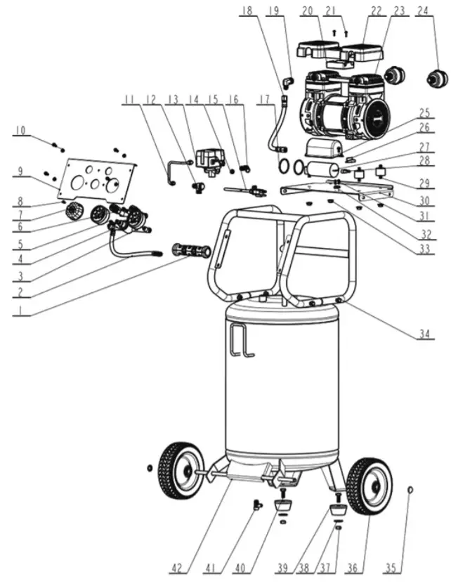
EXPLODED VIEW
| No. | Description | Qty. |
| 1 | Handgrip | 1 |
| 2 | Rubber Hose | 1 |
| 3 | Pressure Gauge | 2 |
| 4 | Pressure Regulator | 1 |
| 5 | Screw M5x12 | 9 |
| 6 | Quick Coupler | 2 |
| 1 | Pressure Regulator Knob | 1 |
| 8 | Screw M4x10 | 1 |
| 9 | Control Panel | 1 |
| 10 | Flange Nut M5 | 7 |
| 11 | Aluminum Tube | 1 |
| 12 | Check Valve | 1 |
| 13 | Pressure Switch | 1 |
| 11 | End Cap | 1 |
| 15 | Power Cord | 1 |
| 16 | Safety Valve | 1 |
| 1/ | 0-Ring | 7 |
| 18 | Metal Tube | 1 |
| 19 | Elbow Fitting | 1 |
| 20 | Retainer | 1 |
| 21 | Self-Tapping Screw ST3 9x16E | 2 |
| 22 | Pump Cover | 1 |
| 23 | Motu! Pump Assembly | 1 |
| 24 | Air Filter | 2 |
| 25 | Capacitor Shroud | 1 |
| 26 | Capacitance Plug | 1 |
| 21 | Capacitor | 1 |
| 28 | Crimp Cap | 2 |
| 79 | Cushion Pad | 4 |
| 30 | Mount Plate | 1 |
| 31 | Screw M4x12 | 2 |
| 32 | Cord Clamp | 1 |
| 33 | Flange Nut M8 | 8 |
| 34 | Screw M8x40 | 4 |
| 35 | Bonnet | 2 |
| 36 | Wheel | 2 |
| 37 | Flange Nut M10 | 7 |
| 38 | Washer 010 | 2 |
| 39 | Rubber Foot | 2 |
| 40 | Bolt M10x25 | 2 |
| 41 | Drain Valve | 1 |
| 42 | Tank | 1 |
WARRANTY
 report this ad
LIMITED LIFETIME WARRANTY
This warranty covers any defects in materials or workmanship of the enclosed product. Mon Industry Ltd. Group will repair or replace any defective materials due to the craftsmanship of the product. This warranty does not cover any problem caused by misuse, abuse, accidents or acts of God, such as floods or hurricanes. Consequential and incidental damages are not covered under this warranty. Coverage terminates if you sell or otherwise transfer the ownership. If you feel you have a defective product, please submit a copy of your receipt to the address below and call 1-888-899-0146 for instructions prior to returning this item to the store or sending it back toAlton Industry Ltd. Group1031 North Raddant RdBatavia, Illinois 60510We will inspect the product and contact you within 72 hours to give you the results of our inspection. We reserve the right to repair or replace the product at our discretion. However,we may replace the product with one of the similar but not exact features. Parts and Service Information available call Alton Industry at 1-888-899-0146 This warranty gives you specific legal rights. You may have other rights which vary from state to state.www.StealthCompressors.con/RegisterSAVE YOUR RECEIPTS THIS WARRANTY IS VOID WITHOUT THEM
[xyz-ips snippet=”download-snippet”]