steinel HF 360-2 KNX Movement Sensor for Home Automation Instruction Manual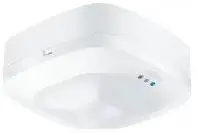
Assembly Instructions
About this document
- Please read carefully and keep in a safe place.
- Under copyright.Reproduction either in whole or in part only with our consent.
- Subject to change in the interest of technical progress.
Symbols
![]() Hazard warning!
Hazard warning!![]() Reference to other information in the document.
Reference to other information in the document.
General safety precautions
![]() Disconnect the power supply before attempting any work on the sensor.
Disconnect the power supply before attempting any work on the sensor.
- During installation, the electric power cable being connected must not be live. Therefore, switch off the power first and use a voltage tester to make sure the wiring is off-circuit.
- Installing the sensor involves work on the mains power supply. This work must therefore be carried out professionally in accordance with national wiring regulations and electrical operating conditions.
- Only use genuine replacement parts
- Repairs may only be made by specialist workshops.
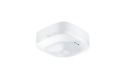
HF 360-2 KNX / Hallway KNX
Proper use
- Sensor for ceiling mounting indoors.
- Connection to the KNX bus system.
The HF 360-2 KNX sensor also detects movements through thin walls. This makes it ideal for WC facilities with toilet cubicles, changing rooms, stairwells, multi-storey car parks and kitchens.The detection zone of the sensor can be precisely limited by ETS.The Hallway KNX Sensor is a highfrequency sensor with a perfect detection zone for corridors. Reach can be adjusted in both directions by ETS.UP: concealed versionAP: surface-mounted version
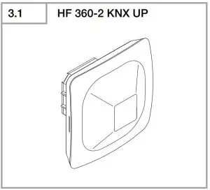
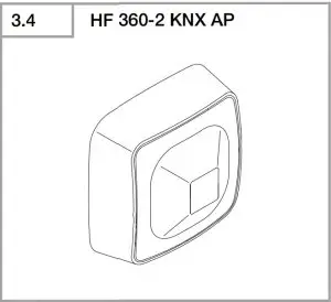
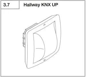
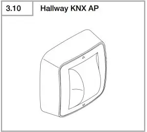
Package contents
(Fig. 3.1, Fig. 3.4, Fig. 3.7, Fig. 3.10)
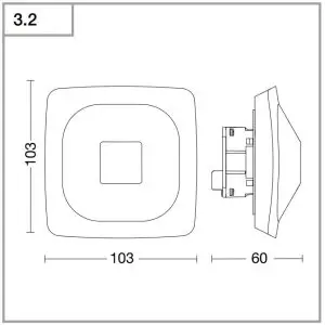
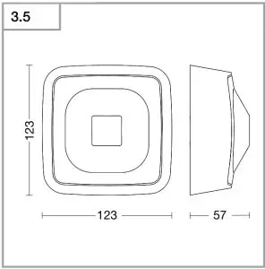
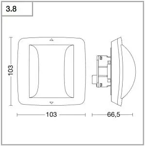
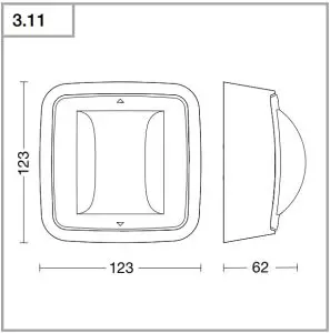
Product dimensions
(Fig. 3.2, Fig. 3.5, Fig. 3.8, Fig. 3.11)
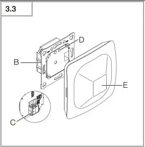
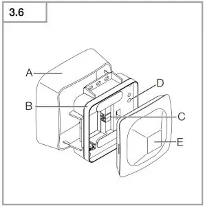
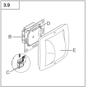
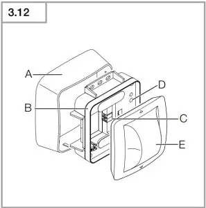
Product components
(Fig. 3.3, Fig. 3.6, Fig. 3.9, Fig. 3.12)
- A Surface-mounting adapter
- B Load module
- C Connecting terminal
- D Programming button
- E Sensor module
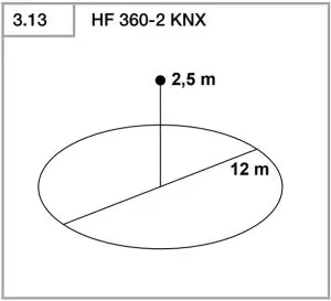
- HF 360-2 KNX detection zone (Fig. 3.13)
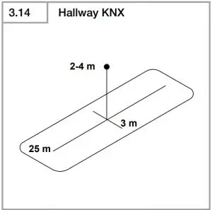
- Hallway KNX detection zone (Fig. 3.14)
Technical specification
- HF 360-2 dimensions (H × W × D):
- Surface-mounted installation: 103 × 103 × 60 mm
- Surface-mounted installation: 123 × 123 × 57 mm
- Hallway dimensions (H × W × D):
- Concealed installation: 103 × 103 × 66.5 mm
- Surface-mounted installation: 123 × 123 × 62 mm
- Power supply: KNX bus voltage 21-30 V
- Mounting height: 2 – 4 m
- Angle of coverage: 360°
- HF 360-2 reach: ø 12 m
- Hallway reach: 24 × 3 m
- Sensor values: Light measurement,
- Temperature: 0-40°C,
- Relative humidity: 0-100%
- Outputs:
- 4 × light output (ON/OFF, scenario dimming level), Dimming level with effect light, 2× constant-lighting control with basic light level, HVAC, presence, temperature,relative humidity, dew point, logic gate, comfort, anti-presence
- Time setting: 30 seconds to 18:12:15 hours (hh:mm:ss), IQ mode
- Twilight setting: 2-1000 lux
- Temperature range: 0°C to +40°C
- IP rating: IP20
- Bluetooth frequency: 2.4-2.48 GHz
- Bluetooth transmission power: 5 dBm/3 mW
- HF 360/Hallway frequency: 5.8 GHz
- Transmission power: 3 dBm/2 mW
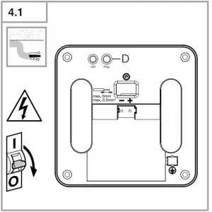
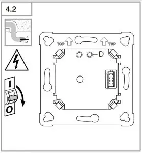
Electrical connection
Surface-mounted connection (Fig. 4.1)Concealed connection (Fig. 4.2)
Installation
- Check all components for damage.
- Do not use the product if it is damaged.
- Select an appropriate mounting location, taking the reach and motion detection into consideration. (Fig. 3.13/3.14)
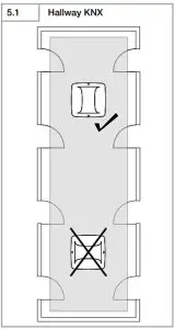
- Aim sensor in appropriate direction. Hallway KNX (Fig. 5.1)
Mounting procedure
Switch off power supply (Fig. 4.1/4.2)
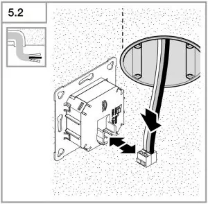
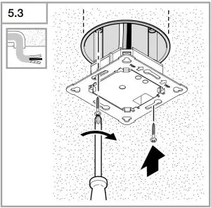
Concealed mounting
- Make plug connection. (Fig. 5.2)
- Firmly screw load module into mounting box. (Fig. 5.3)
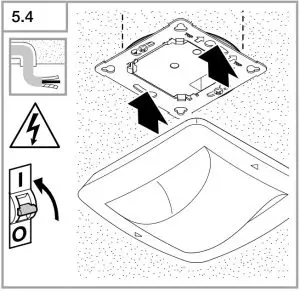
- Fit magnetic sensor module on frame. (Fig. 5.4)
- Switch ON power supply. (Fig. 5.4)
- Make settings.➜ “6. Function and settings”
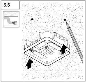
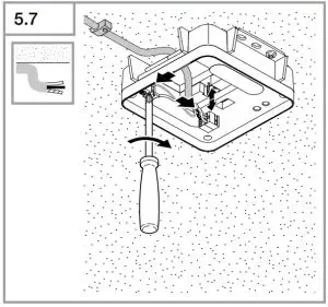
Surface mounting
- Mark drill holes and drill. (Fig. 5.5)
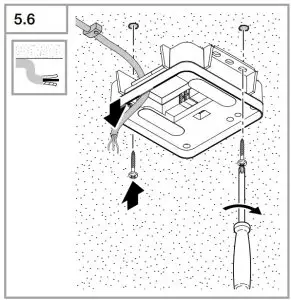
- Screw load module into place. (Fig. 5.6)
- Make plug connection. (Fig. 5.7)
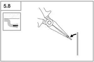
- Break out the mounting tab. (Fig. 5.8)
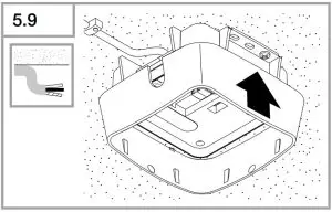
- Fit surface-mounting adapter. (Fig. 5.9)
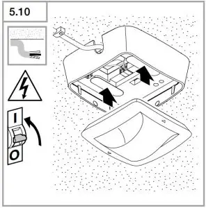
- Fit magnetic sensor module. (Fig. 5.10)
- Switch ON power supply. (Fig. 5.10)
- Make settings.➜ “6. Function and settings”
Function and settings
Factory settings
- See KNX application description
- Test mode
NoteYou will find an application description at knx.steinel.de
Smart Remote appTo read off the sensor values via smartphone or tablet, you must download the STEINEL Smart Remote app from your app store. You will need a Bluetoo capable smartphone or tablet.
Android
iOS
LED function
Initialisation: LED flashes blueNormal mode: LED OFFBluetooth connection active: LED lights up blueError: LED lights up redProgramming mode: LED lights up turquoiseHallway KNX test mode, movement: LED permanently lights up greenHallway KNX test mode, no movement: LED permanently lights up red
Activating functionsActivating with ETS tool via the “General settings” window.Issue physical address.
- Generate application programme in the ETS.
- Load physical address and application programme into the sensor.
- When prompted, press programming button D. (Fig. 4.1/4.2)
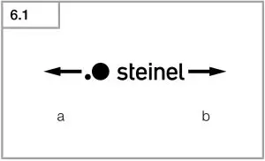
Setting Hallway KNX detectionReach can be set separately for both directions. The Steinel logo on the sensor indicates the direction. (Fig. 6.1)
- a The reach shown by “S” in the ETS points to the direction in which the S in the Steinel logo points.
- b The reach shown by “L” in the ETS points to the direction in which the L in the Steinel logo points.
Maintenance and care
The product requires no maintenance.The sensor can be cleaned with a damp cloth (without detergents) if dirty.
Troubleshooting
Light does not switch ON.
- No supply voltage.
- Check supply voltage
- Switching threshold light level set too low.
- Slowly increase switching threshold light level until light switches ON.
- No presence detection.
- Ensure unobstructed sensor vision.
- Check detection zone.
Lights do not switch OFF.
- Switching threshold light level too high.
- Reduce switching threshold light level.
- Stay-ON time elapsing.
- Wait until stay-ON time elapses;reduce stay
- ON time if necessary.
- Objects moving in the detection zone.
- Check detection zone.
- Sensor switches OFF despite persons being present
Sensor switches OFF despite persons being present
- Reach set too low.
- Change reach.
- Switching threshold light level too low.
- Change switching threshold light level.
Sensor does not switch OFF quickly enough.
- Stay-ON time too long.
- Reduce stay-ON time.
Sensor does not switch ON when persons are present despite it being dark
- Switching threshold light level set too low.
- Increase switching threshold light level.
- Semi-automatic mode activated.
- Activate fully automatic mode orswitch light ON at button.
- 4 hours OFF activated.
- Deactivate 4 hours OFF
Sensor switches ON despite no persons being present.
- Movement within adjacent rooms and floor levels.
- Change reach
- Reducer sensitivity
Wrong temperature indicated.
- Different layers of air.
- Enter correction factor into the ETS.
Disposal
 Electrical and electronic equipment, accessories and packaging must be recycled in an environmentally compatible manner. Do not dispose of electrical and electronic equipment as domestic waste.
EU countries onlyUnder the current European Directive on Waste Electrical and Electronic Equipment and its implementation in national law, electrical and electronic equipment no longer suitable for use must be collected separately and recycled in an environmentally compatible manner.
Conformity
STEINEL Vertrieb GmbH hereby declares that the True Presence COM1/COM2 / Hallway COM1/COM2 radio equipment type conforms to Directive 2014/53/EU.The full wording of the EU Declaration of Conformity is available for downloading from the following Internet address: www.steinel.de
Manufacturer’s Warranty
As purchaser, you are entitled to your statutory rights against the vendor. If these rights exist in your country, they are neither curtailed nor restricted by our Warranty Declaration. We guarantee that your STEINEL Professional sensor product will remain in perfect condition and proper working order for a period of 5 years. We guarantee that this product is free from material-, manufacturing- and design flaws. In addition, we guarantee that all electronic components and cables function in the proper manner and that all materials used and their surfaces are without defects.
Making ClaimsIf you wish to make a claim, please send your product complete and carriage paid with the original receipt of purchase, which must show the date of purchase and product designation, either to your retailer or contact us at STEINEL (UK) Limited, 25 Manasty Road, Axis Park, Orton Southgate, Peterborough, PE2 6UP, for a returns number. For this reason, we recommend that you keep your receipt of purchase in a safe place until the warranty period expires. STEINEL shall assume no liability for the costs or risks involved in returning a product.For information on making claims under the terms of the warranty, please go to www.steinel-professional.de/garantieIf you have a warranty claim or would like to ask any question regarding your product, you are welcome to call us at any time on our Service Hotline 01733 366700.
 report this ad
References
[xyz-ips snippet=”download-snippet”]