![]()
InformationRS LED A1

Installation instructions
Dear Customer,Congratulations on purchasing your new STEINEL SensorLight and thank you for the confidence you have shown in us. You have chosen a high-quality product that has been manufactured, tested, and packed with the greatest care.Please familiarise yourself with these instructions before attempting to install the SensorLight because prolonged reliable and trouble-free operation will only be ensured if it is fitted properly.We hope your new STEINEL SensorLight will bring you lasting pleasure.
System components
- Enclosure
- HF-sensor
- Spacer for surface wiring
- Grub screw
- Sealing plug
- Twilight setting (2 – 2000 lux)
- Time setting (5 sec. – 15 min.)
- Reach setting (3 – 8 m all round)
- Glass shadeI. Mains connection, surface wiringII. Mains connection, concealed wiring
 Safety warnings
- Disconnect the power supply before attempting any work on the unit.
- The electrical connection lead must be dead during installation. Therefore, switch off the power first andcheck that the circuit is dead using a voltage tester.
- Installing the sensor light involves work on the mains voltage supply. This work must therefore be carried out professionally in accordance with applicable national wiring regulations and electrical operating conditions. (D – VDE 0100, A -ÖVE /ÖNORM E8001-1, CH – SEV 1000)
PrincipleThe SensorLight is an active motion detector. The integrated HF-sensor emits high-frequency electromagnetic waves (5.8 GHz) and receives their echo. The sensor detects the change in echo from even the slightest movement in the light’s detection zone. A microprocessor then triggers the “switch light ON” command. Detection is possible through doors, panes of glass, or thin walls.
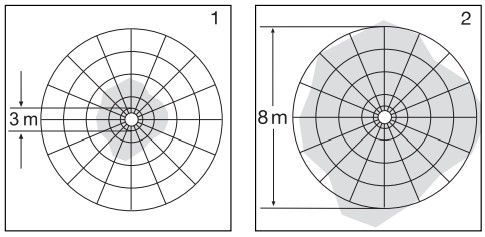
Detection zones for ceiling mounting:
- Minimum reach (3 m dia.)
- Maximum reach (8 m dia.)
 Detection zones for wall mounting:
 - Minimum reach (3 m dia.)
- Maximum reach (8 m dia.)
 Detection zones for wall mounting:
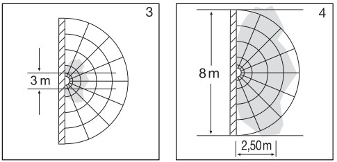
Important: Persons or objects moving towards the light are detected best.Note:The high-frequency output of the HF sensor is approx. 1 mW – that’s just 1,000th of the transmission power of a mobile phone or microwave oven.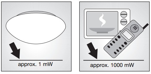
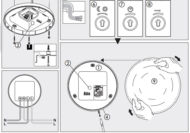
Installation
Important: Make sure the installation site is not subject to vibration.Connecting a dimmer will result in damage to the sensor light.
- Hold enclosure 1 against the wall/ceiling and mark drill holes, paying attention to any existing wiring in the wall/ceiling.
- Drill the holes, insert wall plugs (6 mm dia.).
- Pierce sealing plug for power supply lead.
- Pass power supply leads through.
- Screw enclosure 1 into place.
- Connecting the mains power supply lead (see fig.)The mains power supply lead is a 3-core cable:L = phase conductor (mostly black, brown or grey)N = neutral conductor (usually blue)PE = protective earth conductor (green/yellow)If you are in any doubt, you must identify the cables using a voltage tester; then disconnect from the power supply again. Connect phase (L) and the neutral conductor (N) to the terminal. Insulate any PE protective earth conductor in the power supply cable with adhesive tape.Important: Reversing the connections will result in a short-circuit in the light unit or in your fuse box later on. In this case, you must identify the individual conductors once again and re-connect them. A mains switch for switching the unit ON and OFF may of course be installed in the mains power supply lead.
- Set functions 6,7,8
- Fit glass shade 9 by turning it clockwise and secure in place with the grub screw 4.
Surface wiring:Surface wiring can be carried out as shown in diagram I on page 2.Note:The sealing plugs must be fitted to attain the IP rating.
Technical specifications
| Dimensions (H x W x D): | 275 mm dia. x 95 mm |
| Material: | Plastic (base), opal glass (shade) |
| Mains voltage: | 230 – 240 V, 50 Hz |
| Output: | 11 W LED / 510 lm / 46.6 lm/W |
| Colour temperature: | 3000 kelvin (warm white) |
| LED life expectancy: | 50.000 hours |
| HF-system: | 5.8 GHz |
| Angle of coverage: | 360° with 160° aperture angle also through glass, wood, and stud walls |
| Detection reach: | 3 m – 8 m all round |
| Twilight setting: | 2 – 2000 lux |
| Time setting: | 5 sec. to 15 min. |
| IP rating: | IP 44 |
| Protection class: | II |
| Power consumption: | approx. 0.4 W |
| Temperature range: | -10° C to +40 °C |
Functions
The SensorLight can be put into operation as soon as it has been connected to the mains power supply and enclosure 1 has been fitted. When the light is turned ON manually at the light switch, it switches OFF after 10 secs. for the calibration phase and is then activated for operation in the sensor mode. It is not necessary to actuate the light switch a second time.Light-level setting (response threshold) 6Factory setting: daylight operation (approx. 2000 lux)
 The chosen response threshold can be infinitely varied from approx. 2 – 2000 lux.
Control dial ![]() = daylight operation (approx. 2000 lux)Control dial
= daylight operation (approx. 2000 lux)Control dial ![]() = twilight operation (approx. 2 lux)
= twilight operation (approx. 2 lux)
The control must be turned fully clockwise when adjusting the detection zone and performing the walk test in daylight.
Time setting (switch-OFF delay) 7Factory setting: shortest time (approx. 5 sec.)
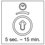 The light’s ON time can be set to any period from approx. 5 sec. and a maximum of 15 min. Any movement detected before this time elapses will re-start the timer.
Control dial max. = longest time (approx. 15 min.)Control dial min.= shortest time (approx. 5 sec.)The shortest time setting is recommended when adjusting the detection zone and performing a functional test.Note: After the light switches OFF, it takes approx. 1 sec. before it is able to start detecting movement again. The light will only switch ON in response to movement once this period has elapsed.
Reach setting (sensitivity)Factory setting: max. reach (approx 8 m) Reach is the term used to describe the diameter of the more or less circular detection zone produced on the ground after mounting the sensor light at a height of 2.5 m.
Control dial max. = reach (approx. 8 m)Control dial min. = reach (approx. 3 m)
Declaration of conformity
This product complies with– Low Voltage Directive 2006/95/EC– EMC Directive 2004/108/EC– RoHS Directive 2011/65/EC– R&TTE Directive 1999/05/EC
Functional Warranty
This STEINEL product has been manufactured with great care, tested for proper operation and safety in accordance with applicable regulations, and then subjected to random sample inspection. STEINEL guarantees that it is in perfect condition and in proper working order. The warranty period is 36 months, starting on the date of sale to the consumer. We will remedy defects caused by material flaws or manufacturing faults. The warranty will be met by repair or replacement at our own discretion. The warranty shall not cover damage to wear parts, damage, or defects caused by improper treatment or maintenance. Further consequential damage to other objects is excluded.Claims under the warranty will only be accepted if the unit is sent fully assembled and well packed complete with a brief description of the fault, a receipt or invoice (date of purchase and dealer’s stamp) to the appropriate Service Centre.
Repair Service:Please ask your nearest service center how to proceed for repairing faults not covered by the warranty or occurring after the warranty expires.
Troubleshooting
| Malfunction | Cause | Remedy |
| SensorLight without power |
|
|
| SensorLight will not switch ON |
|
|
| SensorLight will not switch OFF |
|
|
| SensorLight switches ON without any identifiable movement |
|
|
| SensorLight does not switch ON despite movement |
|
|
STEINEL U. K. LTD.25, Manasty Road · Axis ParkOrton SouthgateGB-Peterborough Cambs PE2 6UPTel.: +44/1733/366-700Fax: +44/1733/366-701[email protected]
110027285 04/2015_H Technische Änderungen vorbehalten. / Subject to technical modification without notice.
References
Датчик движения Steinel – купить датчики движения
【steinel 】施特朗中国官方网站
VSA | De ideale leverancier voor de Business-to-Business markt
Ташев-Галвинг ООД: магазин за машини, инструменти, строителни материали, крепежи и градинска техника
Minusines – Leader du matériel électrique et de l’éclairage
Roliba – En moderne B2B Handelsvirksomhed med stort udvalg
VSA Belgium | De B2B leverancier voor de Belgische markt
Elnas s.r.o.
Domena LOG.SI je naprodaj
Ambergs – apgaismojuma un sensoru tehnikas, santehnikas un celtniecības instrumentu vairumtirgotājs
STEINEL | Steinel Grupul
Hem – KHS
STEINEL | Steinel Group
Daljinsko Upravljanje d.o.o.
Steinel Group | STEINEL
NECO SK a.s. – Administrácia
PRONODIS – Soluções Tecnológicas, Lda
[xyz-ips snippet=”download-snippet”]