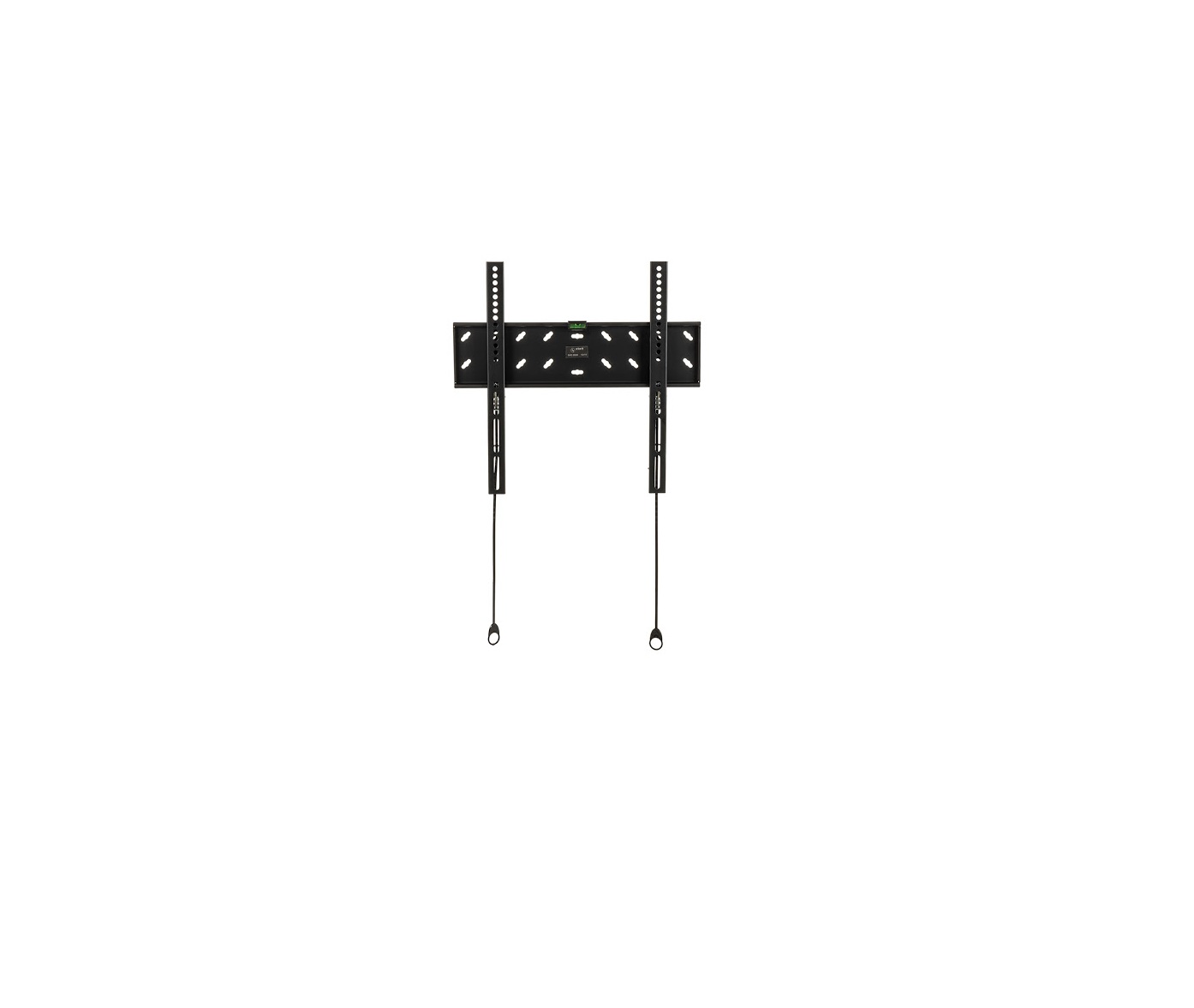
Stell LCD Wall Mount Installation Guide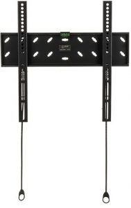
Installation Instruction
UNPACKING INSTRUCTIONS
- Carefully open the carton, remove contents and lay out on cardboard or other protective surface to avoid damage.
- Check package contents against the Supplied Parts List in the next page to assure that all components were received undamaged. Do not use damaged or defective parts.
- Carefully read all instructions before attempting installation.
IMPORTANT SAFETY INFORMATION
Install and operate this device with care. Please read this instruction before beginning the installation, and carefully follow all instructions contained herein. Use proper safety equipment during installation.Please call a qualified installation contractor for help if you:
- If you don`t understand these directions or have any doubts about the safety of the installation.
- If you are uncertain about the nature of your wall, consult a qualified installation contractor.
Do not use this product for any purpose or in any configuration not explicitly specified in this instruction. We hereby disclaims any and all liability for injury or damage arising from incorrect assembly, incorrect mounting, or incorrect use of this product.Note: Specifications and the design are subject to possible modification without notice due to improvement.
IMPORTANT:
- Before installation and use, carefully read this guide and keep it for future use.
- When using electrical tools for tightening bolts, please pay increased attention.
- When tightening bolts make sure not to strip the thread. It could damage the video table / holder. Don`t install this product into a wet or otherwise damaged wall. Fastening materials, which are supplied with the product are designed for installation on to walls from massive wood, bricks or concrete. For assembly on to walls from other materials consult an expert.
- Do not disassemble nor repair the product on your own.
- Never install or service this product if it shows signs of damage. If you are unsure, contact your supplier. Stell takes no responsibility for the faulty installation of this product.
- The product must be placed in such a way that the power socket is accessible after installation. · Sharp edges of this product may cause injury.
- This product is not designed to be handled nor installed by small children or uninstructed persons, unless they are under the supervision of persons responsible for ensuring safety during handling or installation of the product. Children should be under supervision to ensure that they do not tamper with the product. Do not allow children to hang on the product nor to handle it in any other way. If this is not the case, serious injury may occur. Never insert fingers nor other items into the product`s mechanism. Persons could be injured or property damaged.
- Use this product in accordance with the user`s manual and its intended application.
INSTRUCTIONS AND INFORMATION REGARDING THE DISPOSAL OF USED PACKAGING MATERIALSDispose of packaging material at a public waste disposal site.DISPOSAL OF USED ELECTRICAL AND ELECTRONIC APPLIANCES The meaning of the symbol on the product, its accessory or packaging indicates that this product shall not be treated as household waste. Please, dispose of this product at your applicable collection point for the recycling of electrical & electronic equipment waste. Alternatively in some states of the European Union or other European states you may return your products to your local retailer when buying an equivalent new product. The correct disposal of this product will help save valuable natural resources and help in preventing the potential negative impact on the environment and human health, which could be caused as a result of improper liquidation of waste. Please ask your local authorities or the nearest waste collection centre for further details. The improper disposal of this type of waste may fall subject to national regulations for fi nes.For business entities in the European UnionIf you wish to dispose of an electrical or electronic device, request the necessary information from your seller or supplier.Disposal in other countries outside the European UnionIf you wish to dispose of this product, request the necessary information about the correct disposal method from local government departments or from your seller.
 This product meets all the basic EU regulation requirements that relate to it.Changes to the text, design and technical specifications may occur without prior notice and we reserve the right to make these changes.
List of delivered parts
 (1) Wall Plate-a
- (2) Monitor Bracket-b
- (4) M4x12 Bolt-c
- (4) M5x12 Bolt-d
- (4) M6x12 Bolt-e
- (4) M8x20 Bolt-f
- (4) M4 Lock Washer-g
- (4) M5 Lock Washer-h
- (4) M6 Lock Washer-i
- (4) M8 Lock Washer-j
- (4) M4/M5 Washer-k
- (4) M6/M8 Washer-l
- (5) M6x45mm Lag Bolt-m
- (5) Lag Bolt Washer-n
- (5) 8x50mm Concrete Anchor-o
- (1) Bubble Level-p
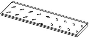 (1) Wall Plate-a
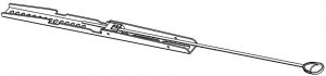 (2) Monitor Bracket-b
 (4) M4x12 Bolt-c
 (4) M6x12 Bolt-e
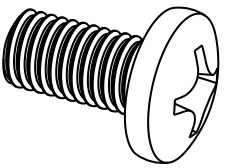 (4) M8x20 Bolt-f
 (4) M4 Lock Washer-g
 (4) M5 Lock Washer-h
 (4) M6 Lock Washer-i
 (4) M8 Lock Washer-j
 (4) M4/M5 Washer-k
 (4) M6/M8 Washer-l
 (5) M6x45mm Lag Bolt-m
 (5) Lag Bolt Washer-n
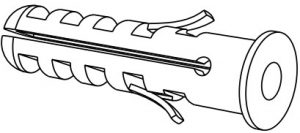 (5) 8x50mm Concrete Anchor-o
 (1) Bubble Level-p
CAUTION!
 WARNING This TV mount must be securely attached to the vertical wall. If the mount is not properly installed it may fall, resulting in possible injury and/or damage.
| Tools Required |
|
|
|
Note:The mounting components and hardware supplied in this package are not designed for installations to walls with steel studs or to cinder block walls. If the hardware you need for your installation is not included, please consult your local hardware store for proper mounting hardware for the application.
Step 1:Mounting the Monitor B Step 1 rackets to a TV with Flat Back
First of all, make sure the diameter of the Bolt(c,d,e,f) your TV requires. Once you have determined the correct diameter, please see the relative diagram as below. You will thread the Bolt into the TV using the correct Lock Washer(g,h,i,j) and Washer(k,l). Please make sure the Monitor Brackets(b) are vertically centered and level with each other.
Step 2:Mounting the Wall Plate to the Wall
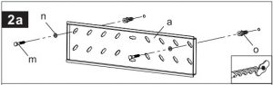
Brick, Solid Concrete and Concrete Block mounting:
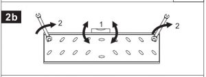
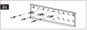
Use the Wall Plate(a) as a template to mark 2 hole locations on the wall. One in the top left slot and another one in the top right slot. Pre-Drill these holes with a 8mm masonry bit to at least 50mm in depth. Insert a Concrete Anchor(o) into each of these holes. Make sure the anchor is seated completely flush with the concrete surface even if there is a layer of drywall or other material in front. Attach the Wall Plate to the wall using 2pcs Lag Bolts(m), 2pcs Lag Bolt Washers(n) and 2pcs Concrete Anchor(o), shown in Diagram 2a. Adjust the level as the Diagram 2b, fasten the Lag Bolts(m). Drill three more holes as the Diagram 2c, attach the rest 3pcs Lag Bolts(m), 3pcs Lag Bolt Washers(n) and 3pcs Concrete Anchor(o)
Wood Stud mounting:
The Wall Plate(a) must be mounted to two wood studs at least 16″(406mm) apart. Use a stud finder to locate two adjacent studs. It is a good idea to verify where the studs are located with an awl or thin nail. Pre-drill a 50mm deep hole at the desired height in each stud using a 3.8mm drill bit. Make sure these holes are in the center area of the studs and level with each other. Use the Wall Plate as a template to mark the location of the second hole in each stud. Drill 50mm deep holes using the 3.8mm drill bit in the marked locations. Attach the Wall Plate to the wall using the 4pcs Lag Bolts(m) and 4pcs Lag Bolt Washers(n).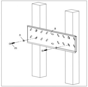
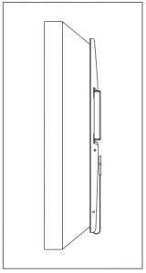
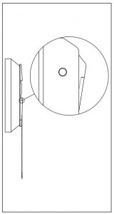
Step 3 :Attaching Monitor to Wall Plate
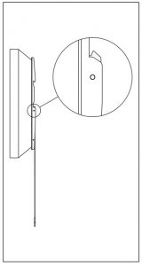
Warning: Some TVs may require two people to lift! We are not responsible for personal injury or product damage.First hook the Monitor Brackets(b) over the top of the wall Plate(a), then let the bottom of the Monitor Brackets rotate to the bottom of the Wall Plate as shown in the Diagram 3A. Push the bottom of TV to lock the Monitor Brackets on the Wall Plate. Before do this step, please make sure the locking system in the close position as the Diagram 3B. Hidden the string as the Diagram 3C. To remove the TV, pull the string to release the locking system as the Diagram 3D.
- Diagram 3A
- Diagram 3B
- Diagram 3C
- Diagram 3D

Thanks for choosing our products, enjoy the using.
[xyz-ips snippet=”download-snippet”]