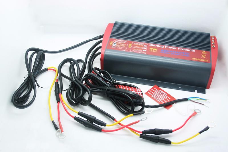
STERLING POWER 12V to 12V IP68 Waterproof Battery to Battery Charger
Specification
- Size: 230mm x 130mm x 50mm (LxWxD)
- Weight: 2.5Kg (5.5 lbs)
- system activated at > 13.3V
- system sleep at < 13.0V after 20 mins current pass shut down at 13.2V on auto control 12.4V on manual control sleep current draw < 1mA
- over voltage trip 16V(output)
- over voltage trip 16V(input)
- low voltage warning N/A (output)
- low voltage warning 6.5V (input)for 24V output x voltages by 2for 36V output x voltages by 3for 48V output x voltages by 4
This appliance is not intended for use by persons (including children) with reduced physical, sensory or mental capabilities, or lack of experience and knowledge, unless they have been given supervision of instruction concerning use of the appliance by a person responsible for their safety.Please ensure children do not tamper with this device.Unit should be installed by a competent electrician.
Quick Installation
Battery Chemistry Profiles – magnet (enclosed) required to swipe, on start up, to change battery type. LED sequence cycles through as below. Remember it is the voltages which are more important than our battery types. After installation, test the voltage from the unit is the desired voltage. The voltage requirements of the battery company will override our recommendations as it is them who are supporting the battery warranty.
BATTERY-TO-BATTERY CHARGER
INSTRUCTIONS
A sophisticated product which will help you to fast and effectively charge a second battery on board your boat or vehicle. Before starting to install the unit, please read and understand these instructions completely, in order to avoid any possible safety risks and to avoid any danger of damaging the unit or your boat / vehicle.
MULTIPLE UNITS CAN BE USED AT THE SAME TIME
SAFETY: General Safety Precautions. Do not install the charger in a room without ventilation; otherwise the unit will overheat and under perform. Fit in as cool a place as possible, this product is waterproof (IP68) however, do not fit underwater. Fit in as cool a place as possible to enable the product to transmit as much heat as possible to maintain its performance.In order to avoid the risk of fire and electrical shock make sure that all your wiring is in good and approved condition and that the cable sizes being used answer the purpose. Do not use the charger with damaged or unsuitable cables!
Precautions against Gas Explosions. This equipment includes cables which may cause arcs or sparks on installation. In order to avoid fire or explosion do not install the unit in a room which contains batteries or highly inflammable materials or in a location that requires ignition protected equipment. This includes any space containing gasoline-powered machinery, fuel tanks or joints, fittings or other connections between components of the fuel system.
Precautions when Working with Batteries. If battery acid contacts skin or clothing, wash immediately with soap and water. If acid enters the eye(s), immediately flood eye(s) with running cold water for at least 20 minutes and seek medical attention immediately.Never smoke or allow a spark or a flame in the vicinity of a battery or an engine.Be extra cautious not to drop a metal tool onto a battery. It may spark or short-circuit the battery or other electrical parts that may cause an explosion.Remove all personal metal items such as rings, bracelets, necklaces, watches and jewellery when working near a battery. A short circuit can produce enough power to melt metal (e.g. jewellery), causing serious burns. Make sure the area around the charger has been well ventilated before you connect the charger. Do not charge the batteries at least 4 hours prior to the installation to avoid the formation of explosive battery gases. If in doubt use a professional.
MAIN PRODUCT FEATURES
The Sterling Battery-to-Battery Charger is a technically advanced charging device which enables you to fast and effectively charge a second battery from your existing on-board DC electrical system. Sterling Batttery-to-Battery Chargers are available in different versions which vary in power, input voltage and output voltage.By now it is widely understood that the best way to charge a battery is to use 4-step charging technology which cannot be achieved from a standard alternator. Without 4 step charging the result is that with such a standard system you will charge your domestic or auxiliary batteries neither fast nor to their full capacity. The Sterling Battery-to-Battery charger was developed and designed to improve this unsatisfactory charging situation on many boats or vehicles.The Sterling Battery-to-Battery Charger, in its standard application, is simply installed between a standard engine battery (input) and a domestic battery (output). It will fool the alternator into working at its maximum ability in order to ensure all its surplus power is utilized to charge the auxiliary battery bank to its maximum capacity without allowing the starter battery to become discharged.The Sterling Battery-to-Battery Charger will charge your extra battery bank about 5 times faster and will put about 50% extra power into them compared to conventional charging technology. It will also increase the life of your batteries by de-sulphating them. The charger can be programmed for all major types of batteries. I.e. open or sealed lead-acid batteries, gel, AGM batteries and lithium all of which will be charged with their recommended charge characteristics.
Product Advantages
- Fast and easy installation. Simply connect the unit to your starter battery and your aux battery as per the illustration.
- No extra connections to the alternator and no extra wiring for a split charge system required. iBattery bank positive leads are insulated. Engine starter battery is always well maintained.
- Several battery-to-battery chargers can be used in parallel for higher output power or multiple battery banks.
- No voltage rise on the alternator or the starter battery, thus no problems with the engine management system.
- No warranty issues as the alternator and the main electrical system remains untouched.
How it works. The Sterling Battery-to-Battery Charger constantly monitors the engine start battery. When the starter battery voltage exceeds 13.3V (26.6V at 24V) (which is usually the case when it is being charged) the charger will activate itself. It will then start its charging operation during which the starter battery voltage will be pulled down to no less than 13V. This enables the engine battery to still receive sufficient charge and ensures that the alternator works at its full potential. The unit takes the 13V from the starter battery into the control box and boosts it up to a maximum of 15.0V (depending on what battery type and voltage has been selected, for 24V out then x 2 for 36V then x 3) at the output. This will charge the secondary bank of batteries to their full capacity. The charger then automatically calculates the optimum absorption time and keeps the voltage at absorption level until the batteries are fully charged. After that, the system will maintain the batteries at a lower float voltage, while always ensuring that the engine starter battery has priority.
INSTALLATION
Install the unit as per the wiring diagram. Do not cut the cables as they come pre-wired with fuses. If the cables are cut ensure fuses are added, there is no warranty if the fuses are removed. Fit in a cool and well ventilated place.
Automatic of Manual (Regen. Activation). There are 2 ways to activate this product
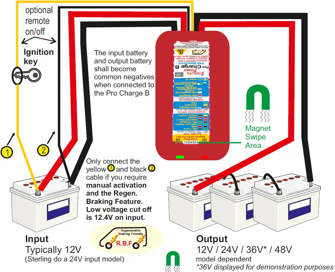
- Automatic, 95% of installations can take advantage of the automatic activation, the unit will activate itself when it senses an input voltage in excess of about 13.3V (the engine is running) and switches itself off at 13.0V (the engine has been switched off). The 2 small ignition feed wires need not be installed for this installation.
- Manual activation, there may be some unique installations where the auto activation is not desired and the unit needs to be activated or deactivated by a direct command, i.e. ‘on’ and ‘off’ via a switch or other signal. In this case the extra wiring must be completed to supply the signal to activate the unit. Cables 1 and 2 (as per the installation guide must be installed, the unit will simply work provided there is 12.4V to 15V on the input cable and stop when the feed is removed). Still has a low voltage restrictions of 12.4V. This feature is also good if you have a regenerative braking software routine on your vehicle engine. This is where the main voltage can drop as low as 12.4V from the alternator. Important, no special setup is required to activate manual activation mode, simply connect up the ignition feed wires (as per the instructions), however, once manual activation mode has been activated (just once) the unit will permanently lock onto this mode until deactivated using the magnet and instructions.
Install the charger like any other high power battery charger. It can be mounted in any orientation or direction.Do not install the unit on carpeted, upholstered, vinyl or varnished surfaces.Fit it as close to the primary (starter) batteries as possible.
- Select the battery type you require from the list below and printed on the label.
Program the battery type into the unit: Use the magnetic switch to program the battery type according to the following instructions – please turn over.
Battery Type Setting
Selecting your battery type: Unfortunately, with modern batteries this may not be as simple as it first appears. If in doubt, use the settings with the lower boost voltage settings. This will not cause a problem, however, the higher setting could, if used on the wrong battery type. You can always adjust the setting at a later date when you find the correct information you require. It is no big deal picking a setting too low, but it is a big deal picking one too high as this could permanently damage your batteries.
Battery Charging Terminology
We use the word bulk/boost, also called constant current, to describe the first stage of the charge cycle. All it means is that the charger is offering the maximum possible current to the batteries (and the batteries will absorb all the current up to the max current of the charger) for as long as possible, until the boost voltage will be reached. Then the current will taper off and the charger switches into the absorption phase. The boost voltage will be kept for a calculated time until after this time the voltage will drop to float. While on float if a battery load pulls the battery voltage down then the unit will reset the boost and do another fast charge cycle. The float voltage which will maintain your batteries and also allows the system to act as a power pack to supply power being used on the boat or vehicle without touching the newly charged batteries. The time on absorption is determined by the state of charge of the battery bank and the ratio of your battery bank size and the size of the charger. The internal software program works this out every time the charger is used and will vary within the parameters shown as time.The actual voltages are approximate (varies depending on battery charge status) time settings for all the different battery types are all shown on the front page below the wiring diagram for each battery type.Some modern batteries have had calcium added to their plates in order to reduce water loss in the battery. The down side with this is that you need a higher charge voltage to get the batteries charged. This setting goes up as far as 15.0 volts on boost and can have a detrimental effect on some voltage-senstive equipment on the boat/vehicle. It is important to ensure that your equipment works safely at a voltage in the region of 15.4V (x2 for 24V, x3 for 36V, x4 for 48V systems) before selecting this option, most equipment should be okay but maybe not all.
Start up and test procedure
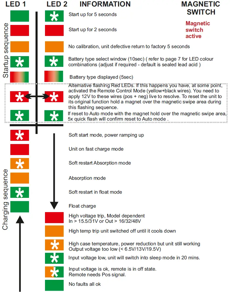
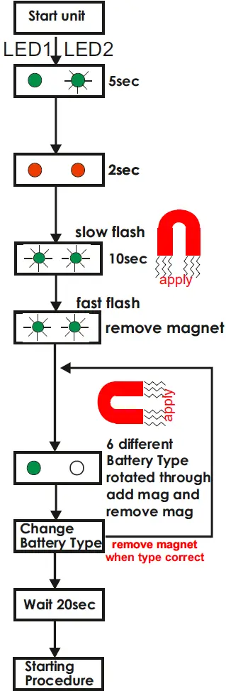
When the unit is connected, it senses the voltage on the input battery. The voltage must be above 13.3V to activate the unit (on all 12-24V, 36V, 48V units). In order to get to this voltage on the input battery a charging source on the input battery is required (e.g an alternator, battery charger etc). When the unit first starts up, the LED sequence is, 2 green LEDs on (LED 2 flashing) for 5 sec. This confirms the LEDs are ok and the correct way round. Then 2 red LEDs on for 2 secs. After green + red then again 2 green LEDs will flash for about 10 secs, (this is the battery type selector window) you can change your battery type during this phase using a magnet. If the battery type is ok, then the unit will simply continue into the charging program as per normal.
If on start up nothing happens, then:
- Test the primary battery voltage. It must be above 13.3V. To see the unit working start up the engine and ensure you are getting at least 13.3V at the starter / primary battery.
- This unit is fitted with a safety system where, if the output voltage drops below 6.5V at 12V (pro rate for 24V/36V/48V) then the unit will not work. In order to activate in the field then you need to raise the voltage on the output bank above 6.7V at 12V (pro rate for 24V/36V/48V). Warning: at this low voltage your batteries may well be badly damaged and beyond repair.
IMPORTANT: The maximum current is only available if the input voltage is larger than 13.5V. Between 13.5V and 13.3V input voltage the current is tapering off.
This product has 2 tri coloured LEDs located at the side of the product labelled LED1 and LED2. Each LED has the ability to emit 3 colours and also flash (denotes the LED colour which flashes). Red, Orange and Green, by using the 2 LEDs and the 3 colours we can mix them to give various amounts of information to the user.
Battery Type Selection /Setup Procedure
- Wire the unit according to the instructions but do not connect the output side of the unit to the output battery bank if you require a battery type adjustment, or, in the event of a re-adjustment being made on an excising installation then remove the output from the output battery bank (leaving the input connected) during the procedure.
- Have a magnet in one hand, at least 14 inches away from the product (so as not to cause any premature activation). Please be ready as you only have about 10 sec to enter the adjustment window once the product is activated.
- Activate the unit (switch on) the start up sequence will be 2 x green LEDs for about 5 seconds (LED1 on solid and LED2 flashing) then 2 red LEDs for about 2 sec (LED1 on solid and LED2 flashing), this is simply to confirm the LEDs are ok and the correct way round (If 2 yellow lights appear then the unit has not been factory set. This should not happen).
- Then the 2 green LEDs will start to flash slowly for 10 seconds. This is the window where you must apply the magnet if you wish to change the battery chemistry. Apply and hold the magnet at the region marked ‘magnetic switch position’. It will then confirm that you are in battery select mode by the two green LEDs flashing faster. You then must remove the magnet.
- To cycle through the battery types the 2 flashing green lights will stop flashing. Re-apply the magnet to the magnetic switch position. The LEDs will now run through the battery type options, with a different option being presented every 4 seconds. When the battery type required is presented simply remove the magnet (please note with strong magnets it may skip to the next battery type, please make sure it locks onto the battery type you want). If the wrong battery type is locked then simply re-apply the magnet again. If the battery type is ok then keep the magnet well away and the software will permanently lock this battery type into the software after about 20 seconds of no magnetic activity. Once it has locked then it will remain there until it is required to re adjust in the future.Fault condition: for safety reasons if the output battery is very discharged this unit will not work. Also your batteries could be extremely badly damaged in this event due to extreme discharge. Output battery on 12V if less than 6.5V, on 24V if less than 13V and on 36V if less than 19.5V, 48V less than 26.0V, the charger will not work.
If red lights are flashing alternatively then you have to reconnect your yellow/black to 12V to reinstate the remote control. To set unit back to automatic mode swipe the magnet across the swipe area.

Customer Service & Warranty
Your 100 % satisfaction is our goal. We realise that every customer and circumstance is unique. If you have a problem, question, or comment please do not hesitate to contact us. We welcome you to contact us even after the warranty and return time has passed.
Product Warranty
Each product manufactured by Sterling Power comes with at least a 2 year limited factory warranty. Certain Products have a warranty period of time greater than 2 years. Each product is guaranteed against defects in material or workmanship from the date of purchase. At our discretion, we will repair or replace free of charge any defects in material or workmanship that fall within the warranty period of the Sterling Power product. The following conditions do apply:
- The original receipt or proof of purchase must be submitted to claim warranty. If proof cannot be located a warranty is calculated from the date of manufacture.
- Our warranty covers manufacture and material defects. Damages caused by abuse, neglect, accident, alterations and improper use are not covered under our warranty.
- Warranty is null and void if damage occurs due to negligent repairs.
- Customer is responsible for inbound shipping costs of the product to Sterling Power either in the USA or England.
- Sterling Power will ship the repaired or warranty replacement product back to the purchaser at their cost.
If your order was damaged in transit or arrives with an error, please contact us ASAP so we may take care of the matter promptly and at no expense to you. This only applies for shipping which was undertaken by our company and does not apply for shipping organised by yourself. Please do not throw out any shipping or packaging materials.All returns for any reason will require a proof of purchase with the purchase date. The proof of purchase must be sent with the returned shipment. If you have no proof of purchase call the vendor who supplied you and acquire the appropriate documentation.To make a claim under warranty, call our customer care line at numbers on web site where we make the best effort to repair or replace the product, if found to be defective within the terms of the warranty. Sterling Power will ship the repaired or warranty replacement product back to the purchaser, if purchased from us.Please review the documentation included with your purchase. Our warranty only covers orders purchased from Sterling Power. We cannot accept warranty claims from any other Sterling Power distributor. Purchase or other acceptance of the product shall be on the condition and agreement that Sterling Power USA LLC and Sterling Power LTD shall not be liable for incidental or consequential damages of any kind. Some states may not allow the exclusion or limitation of consequential damages, so, the above limitations may not apply to you. Additionally, Sterling Power USA and Sterling Power LTD neither assumes nor authorizes any person for any obligation or liability in connection with the sale of this product. This warranty is made in lieu of all other obligations or liabilities. This warranty provides you specific legal rights and you may also have other rights, which vary from state to state. This warranty is in lieu of all other, expressed or implied.
Sterling Power Products LtdEnglandwww.sterling-power.com
Sterling Power USAUSAwww.sterling-power-usa.com
 report this ad
![]()
References
[xyz-ips snippet=”download-snippet”]