STETSOM DB3000 Digital Bass Amplifier

Introduction
Thank you so much for choosing a Stetsom product! The chosen amplifier has been developed with the most advanced technology for those who are looking for high performance audio systems with one or more speakers and “pro car audio” system.
Before installing
Please read this manual carefully.
- All product connections must be made with the product turned OFF.
- A fuse must be installed between the amplifier and the battery is required to protect against overcharging. The fuse has to be installed as close to the battery as possible. Check the proper fuse for the amplifier according to its consumption.
- Use gauges recommended in this manual to avoid the overheating of the cables to obtain maximum power.
- Keep the cables as short as possible to increase sound fidelity and avoid potential power losses.
- Route the installation cables as far away as possible from the original vehicle wiring as it may cause interference and noise in your audio system.
- Perform the installation in a firm, ventilated and dry place.
- Installation must be done by a qualified professional.
If you have questions , contact the store where the purchase or installation was made. For more information please contact ourCustomer Service: BR +55 18 2104-9412.
Input, output and audio controls
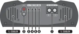
- COOLERS: It cools the amplifier. Install in a cool place being careful to not obstruct the air vents.
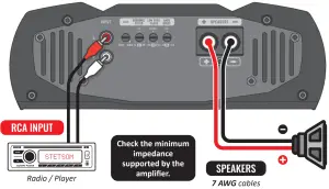
- INPUT: Input of the signal to be amplified. Connect to the radio/player using high quality shielded RCA cables to prevent unwanted noise.
- GAIN: Level control for the signal at the amplifier’s input.
- SUBSONIC FILTER: This variable control allows you to select the initial frequency from 5Hz to 35Hz that will be reproduced by the amplifier.
- LOW PASS FILTER: This variable control allows you to select the final frequency from 35Hz to 250Hz that will be reproduced by the amplifier.
- BASS BOOST: Fixed bass boost at 35Hz with adjustable actuation from 0 to +18dB.
- OUTPUT CONNECTOR (SPEAKERS): MONO output of amplified signal for speakers connection. Check the minimum impedance and polarities before performing the installation.

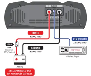
- POSITIVE POWER SUPPLY CONNECTOR: Connect to the positive battery terminal of the battery using a minimum 4 AWG cable with a fuse/ circuit breaker (150A) installed as close to the battery as possible.
- REMOTE CONNECTOR (REM): Allows automatic activation of the amplifier when turning on the radio/player. Connect to the remote output of the radio/player using a cable a minimum of 18 AWG.
- NEGATIVE POWER SUPPLY CONNECTOR: Connect to the negative terminal of the battery using a cable with a minimum of 4 AWG.

LED indicators

Smart protection system
In the event of a problems, the amplifier will turn off and the PROT LED will flash. Depending on the problem, the led will flash a certain number of times indicating the cause of the problem, as shown in the table below:
 |
Problem: Short circuit or output overload.Solution: Make sure that the speaker cables are well isolated. Verify the minimum impedance supported. |
 |
Problem: OverheatingSolution: Verify that the amplifier is in a well-ventilated place and that the coolers are not obstructed |
 |
Problem: Low battery.Solution: Battery consumption is normal when using the amplifier. Recharge the battery. |
 |
Problem: Tension higher than allowed.Solution: Verify the power supply/battery system. |
Installation
Specification of the cables for proper installation:
| ▪ Power connectors (positive/negative) | 4 AWG |
| ▪ Remote connector | 18 AWG |
| ▪ Output signal connectors (speakers) . | 7 AWG |
| ▪ Fuses or circuit breakers | 150A |
The use of a fuse or circuit breaker is mandatory to protect the system from short circuits and overload. Install them as close to the battery as possible.
 |
Installation should only be done by qualified professionals with the product turned OFF. |
Troubleshooting
AMPLIFIER DOES NOT TURN ON:
- Verify that the cables are connected correctly. Make sure all connections have electrical and mechanical contact.
- Fuses or circuit breakers may be defective or blown. Check the condition of the circuit breakers and make sure they are compatible with the equipment consumption.
- Make sure that the battery is charged sufficiently for the product to operate.
NO SOUND:
- The cables to the speakers or RCA plugs may not be connected incorrectly or defective.
- Check that the GAIN and FILTER controls are not out of adjustment.
PROT LED FLASHING:
- Make sure that the product’s air vents are not blocked and that the product is not overheating.
- Speakers or cables are shorted. Check speakers, cables and connections.
- Check the battery charge level.
SOUND DISTORTIONS:
- The speakers may be overloaded or defective, lower the level and then readjust the level. This setting can be adjusted as follows:a) On the radio/player, play any musical signal and set the volume to 80% of the maximum (if the maximum volume of the radio /player is 45 (100%), set to 36 (80%).b) On the amplifier, begin with the LEVEL control at minimum, increase gradually until the LED CLIP starts to flash. Slowly decrease the LEVEL until the led goes out completely.
WEAK OF BASS:
- Cables of the speakers may be reversed and (speakers out-of-phase).
NOISE AND FAILURE IN SOUND:
- Make sure that the installation is not close to the vehicle’s original wiring as it may cause interference and noise in the audio signal.
- Create a separate power connection for the sound system. Use a fuse/ circuit breaker as close to the battery as possible for protection.
- Make a good grounding for the amplifier. To do this, remove the paint from the vehicle chassis at the desired point. Attach the wire using a ground terminal. To prevent oxidation, isolate with paint.
- Do not loop the ground. Avoid using multiple grounds. If possible, use a star connection, so all the grounds run from a single point.
Technical specifications
| Minimum output impedance: |
1 OHM |
2 OHMs |
| Number of channels: | 1 | |
| Power output @ 14.4V: | 3950W RMS @ 1 Ohm2600W RMS @ 2 Ohms | 3700W RMS @ 2 Ohms2350W RMS @ 4 Ohms |
| Power output @ 12.6V: | 3100W RMS @ 1 Ohm2000W RMS @ 2 Ohms | 3000W RMS @ 2 Ohms2000W RMS @ 4 Ohms |
| Input sensitivity: |
200mV |
|
| Signal to noise ratio |
>90dB |
|
| Frequency response (-3dB): |
5Hz ~ 250Hz |
|
| Low pass filter (crossover): |
35Hz ~ 250Hz |
|
| Subsonic filter (crossover): |
5Hz ~ 35Hz |
|
| Bass boost: |
Boost: 0 ~ +18dB (Fixed 35Hz) |
|
| Input impedance: |
20K Ohms |
|
| Supply voltage: |
9V ~ 16V |
|
| Musical consumption @ 12.6V: |
169A |
147A |
| BASS consumption @ 12.6V: |
338A |
295A |
| Dimensions (H x W x L): |
3.07” x 9.11” x 10.8” |
|
| Weight |
6.6 lb |
|
The data measured are based on STETSOM laboratory equipment. Test reference in frequency from 60hz with THD + N at ≤1% in impedances as indicated in each measurement. The electronic components and the manufacturing process may present manufacturing variations, thus leading to a variation in the measurements made. |
 |
Any updates made in this manual will be available for customers to consult free of charge on the brand’s site.It is recommended that the updated manual be consulted whenever needed |
Images contained in this manual are merely illustrative and may differ from the actual product.
Warranty Term
STETSOM, through its network of Authorized Technical Assistance Providers, guarantees technical assistance to the purchaser of their products. The repairs of any defects duly established as being of the manufacturer will be done without cost for replacement components or parts and repair labor. The repairs will be done by the Authorized Technical Assistance Provider specially designated by STETSOM.
CONSULT THE LIST OF AUTHORIZED TECHNICAL ASSISTANCE PROVIDERS ON OUR WEBSITE: : www.stetsom.com.br/en/assistencias-tecnicaIf you do not locate technical assistance in your city, please contact us at: BR +55 18 2104-9412
WARRANTY CONDITIONS:Our warranty is 1 (one) year against manufacturing defects. Its validity starts on the date of the Sale to the FINAL Consumer. To claim the benefits of this warranty, you must present one of the following documents: the Final Consumer’s SALE NOTE or this completed CERTIFICATE.
SITUATIONS THAT VOID THE WARRANTY:
- 1 year after the issuance of the invoice of sale to the consumer or 1 year after the certificate of warranty is filled out (dated and stamped by the retailer or installer) or 1 year from date of manufacture.
- Violation of seals, alteration or removal of the product’s serial or lot number.
- If the product suffers misuse or careless accidents involving: Water, Fire or Fall, or is installed in conditions contrary to the guidelines contained in the installation manual that accompanies the product.
- Damages and changes in the circuit or adaptation of non-original parts.
- If you use installation techniques contrary to those given in the manual.
QUESTIONS AND ADVICE:STETSOM offers Customer Services to answer questions and give advice about their products and services. Please contact us through the channels: Phone: BR +55 18 2104-9412 / E-mail: [email protected]Site: www.stetsom.com
 report this ad
References
[xyz-ips snippet=”download-snippet”]