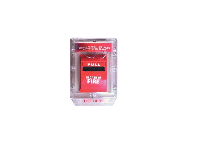
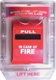
STI Stopper II SERIES Instructions
UL Listed Models Included on this Install Sheet
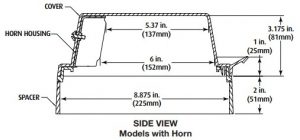
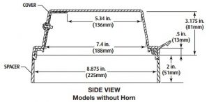
Indoor Use:STI-1100 With horn for flush mounted appliancesSTI-1100 RC With horn for flush mounted appliances includes relay contacts capable of operating from 9-24 VDC remote power or internal 9V battery powerSTI-1130 With horn and 2″ conduit spacer for surface mounted appliances and electrical boxesSTI-1130 RC Surface mounted version of the 1100RC includes 2″ conduit spacerSTI-1200 Without horn for flush mounted appliances.STI-1230 Without horn, with 2″ conduit spacer for surface mounted appliances and electrical boxes.
Indoor/Outdoor Use (Weather Stopper Models)
All outdoor units include necessary gaskets.STI-1150 With horn for flush mounted appliancesSTI-1150RC With horn for flush mounted appliances includes relay contacts capable of operating from 9-24 VDC remote power or internal 9V battery power also includes weather gasketSTI-1155 Surface mounted version of theSTI-1150 includes 2″ conduit spacerSTI-1155RC Surface mounted version of theSTI-1150RC includes 2″ conduit spacerSTI-1250 Without horn for flush mounted appliancesSTI-3150 Without horn with 2″ conduit spacer for surface mounted appliances and electrical boxesSTI-1102 Replacement horn for cover with alarm Custom-LBL Custom text message for horn housing.
Testing Approvals
It has been tested and approved or listed by:
- Underwriter Laboratories and cUL No. 49G2
- UL/cUL Certified to meet ADA compliance
- Weather Stopper models provide a raintight seal to the NEMA 3R standard.
- NYC BSA #947-81-5A
- Obtain local fire marshal approval for State of California
Patents
- Stopper II is protected by US registration No. 4192877.
Specifications
Polycarbonate Enclosure
- Flammability: UL94 V-2
- Wall Thickness: 095 inches
- NEMA Rating: Meets NEMA 3R when mounted to smooth non-masonry surfaces.
![]() WARNING: This product can expose you to chemicals including Dichloromethane, which is known to the State of California to cause cancer, and Bisphenol A (BPA), which is known to the State of California to cause birth defects or other reproductive harm For more information go to www.P65Warnings.ca.gov.
WARNING: This product can expose you to chemicals including Dichloromethane, which is known to the State of California to cause cancer, and Bisphenol A (BPA), which is known to the State of California to cause birth defects or other reproductive harm For more information go to www.P65Warnings.ca.gov.
Gaskets
- Closed Cell IV2 with pressure sensitive adhesive
- Replace after 5 years
|
Horn |
9V |
12V |
24V |
| Low (95 dB @ 1 ft.) |
96mA |
107mA |
125mA |
| High (105 dB @ 1 ft.) |
130mA |
145mA |
182mA |
| Min. Operating Req. |
2V @ 20mA |
4V @ 20mA |
4V @ 20mA |
|
Relay |
9V |
12V |
24V |
| Relay |
23mA |
25mA |
29mA |
| Min. Activation Voltage |
3.7V |
5.8V |
5.8V |
| Reset Voltage |
1.5V |
3.3V |
3.3V |
| Dry Contact Rating (type Form “C”) |
<13V, 1A |
<30V, 1A |
<30, 1A |
Temperature Range:
- 40° to 120°F (-40° to 49°C)
- For temperatures below -4°F (-20°C) recommend using remote power source.
Warranty
- Three year guarantee against breakage of polycarbonate housing in normal use (one year on electro mechanical and electronic components).
- Electronic warranty form at www.sti-usa.com/wc14.
Important Notice
Stopper II is intended to be used in areas where the incidence of false fire alarms from manual pull stations is high or has proven to be a serious problem. Any disadvantage of this device is more than balanced when one considers the consequences of false fire alarms, especially if fire service personnel and equipment are responding to a false fire alarm when they are needed for a real fire somewhere else. Add to this the disruption to the facility when false alarms occur. If you have, or may have, a problem with false fire alarms or physical/ weather damage to your fire alarm activation devices, the Stopper II could prove invaluable.
Installation Notes
- When used outdoors, the manual pull station must also be rated for outdoor use.
- The relay contacts on Model STI-1100RC, STI-1130RC, STI-1150RC and STI-1155RC, UL Listing does not permit connection to fire alarm or a life safety function.
- According to UL Listing, models powered from an external power source cannot be supplied from the fire alarm panel.
- When properly installed the operation of this cover will not interfere with the function of your life safety system.
- A backplate and gaskets must be used to achieve NEMA 3R integrity.
- Horn must be tested annually for proper operation. Battery replacement is recommended annually dependent on use and battery expiration date.
- If mounting to an uneven surface STI recommends the use of the STI-1280 backplate to ensure proper sealing. If wire access or screw mounting holes are needed, backplate may be drilled as necessary.
Installation Instructions
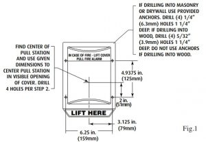
- The power switch is in the “OFF” position (Fig. 5). Using frame or optional STI-1280 backplate (recommended with all Weather Stopper® models) as a template, mark mounting holes on wall taking into consideration placement of pull station or refer to Fig. 1 for dimensional hole placement from center of clear opening.NOTE: Be sure cover will not interfere with operation of the pull station when installed.

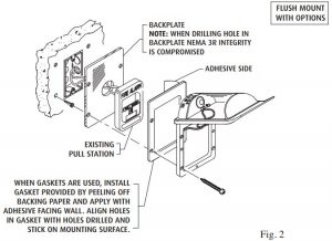
- If using STI-1280 backplate, refer to Fig. 2 and 3 for install instructions depending on your application.NOTE: When drilling hole in backplate NEMA 3R integrity is compromised. Weather Stopper, STI-1250, is designed to meet the requirements of IP54.
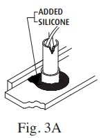
- Align frame and put screws through frame holes, into anchors and tighten (if used, through spacer, gaskets and optional backplate). For STI-1200, continue to Step 8.NOTE: When using STI-3100 spacer, be sure to install conduit knockout, any additional ventilation and gaskets before you tighten to the wall. When using conduit gasket STI-3004, place gasket around conduit in proper location and install the spacer. For added protection a bead of silicone may be applied to conduit fitting and between STI-1280 backplate and wall (Fig. 3A). Refer to exploded view of flush and surface mount installation options Fig. 2 and 3. Weather Stopper, STI-3150, IP equivalency may vary depending on selection of conduit inserts used.
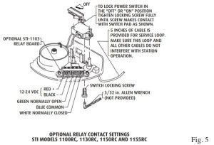
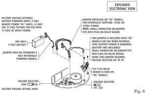
- Make any external connections for remote power or relay options. Refer to Fig. 5 for wiring details.
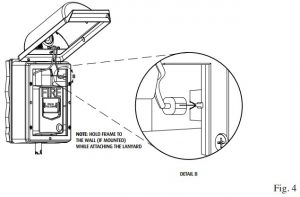
- For models using the 2″ spacer to install the cover, insert the cable end stop into the pocket on the inside of the frame. Hold the frame against the wall and pull the cable to lock into the slot. Repeat for 2nd cable (FIG. 4).
- Slide power switch, on back of horn housing, to “ON” position (Fig. 5). When power is connected to unit horn should sound.NOTE: If external power source is used horn will not sound until power is turned on at source.
- Push switch in to silence horn while tightening switch locking screw (Fig. 5 for location of screw). This prevents slide switch from being shut off during unauthorized use.NOTE: Surface Mount version is shipped with screw in locked position.
- Close cover on frame by aligning tabs on cover with slots on frame and push bottom on tightly, horn should silence. To test: lift cover, horn should sound, and return cover to frame to silence horn. Unit is armed for operation.

Gasket Installation
Use of gaskets is necessary to ensure a proper seal in weatherproof applications. Weather Stopper models ship complete with all necessary gaskets and should be used accordingly. For flush mount weather applications, one STI-3002 must be used between the frame or spacer and wall or backplate (see Fig. 3). An STI-3004 gasket must be used around all entering conduit. For surface mount applications, the conduit insert with holes is available for installation in the bottom knockout of the conduit spacer. This helps prevent excessive condensation buildup; but may allow for dust entry. STI recommends gasket replacement every five years. (UL requires listing of pull station to be UL Listed for outdoor installations.)
Battery Replacement Instructions
- Remove the cover from the frame. It is not necessary to remove the cables from the frame.
- Use a 3/32″ allen wrench to loosen the button head screw located next to the switch far enough to slide the switch to the “off” position.
- Holding the horn housing and cover in one hand, remove the button head screw located on the top of the cover with the same allen wrench.
- Set the clear cover aside and remove the horn housing cover.
- Replace the battery with a 9 Volt battery only. Be careful to keep the wires away from the slide switch and the micro-switch.
- Reassemble the unit making sure that the horn housing fits into the tabs on the horn housing cover; and that this assembly is mounted evenly into the clear cover.
- Replace the button head screw through the top of the clear cover and into the top of the horn.
- Slide the switch to the “on” position. The horn should sound.
- Push the switch in to silence horn while tightening the “on” position locking screw.
- Replace the cover onto the frame and test by removing the cover from the frame. The horn should sound when removed and silence when cover is replaced. If unit does not operate correctly, contact Safety Technology International, Inc.
Polycarbonate Cleaning Instructions
Rinse with water to remove abrasive dust and dirt. Wash with soap or mild detergent, using a soft cloth. Rinse once more, then dry with a soft cloth or chamois. Exercise caution when using water inside enclosure. Make sure unit is completely dry inside before reassembling. To remove grease or wet paint from exterior of cover, rub gently with a cloth thoroughly wetted with Naptha. Then wash and rinse. (Do not use razor blades.)
Options Available
KIT-316 Louvers for STI-3100KIT-H19015 Two 3/32″ Allen wrenchesSTI-1102 Replacement horn for cover with alarmSTI-1280 BackplateSTI-3002 Weather gasketSTI-3003 Conduit gasketSTI-3100 2″ conduit spacer with ½” conduit entrySTI-3104 2″ conduit spacer with ¾” conduit entry (includes one ¾” conduit entry gasket)
Product Dimensions
EXTERNAL DIMENSIONS: Flush 7.1 x 10.0 x 3.3 in. (180 x 254 x 84 mm)W x H x D: Surface 7.23 x 10.1 x 5.28 in. (184 x 256 x 134 mm)

Safety Technology International2306 Airport RdWaterford, MI 48327,USA Phone: 248-673-9898Fax: 248-673-1246www.sti-usa.comSafety Technology International LtdTaylor House · 34 Sherwood Road · Bromsgrove, Worcestershire · B60 3DR · EnglandTel: +44 (0)1527 520 999Fax: +44 (0)1527 501 999www.sti-emea.com
References
[xyz-ips snippet=”download-snippet”]