
Stieble Eltron CE/CES/CERO Series Electronically
Controlled Instantaneous Water Heater User Manual

OPERATION
General information
Read this entire manual. Failure to follow all the guides, instructions and rules could cause personal injury or property damage. Improper installation, adjustment, alteration, service and use of this unit can result in serious injury.
This unit must be installed by a licensed electrician and plumber. The installation must comply with all national, state and local plumbing and electric codes. Proper installation is the responsibility of the installer. Failure to comply with the installation and operating instructions or improper use voids the warranty.
Save these instructions for future reference. The installer should leave these instructions with the consumer.
If you have any questions regarding the installation, use or operation of this water heater, or if you need any additional installation manuals, please call our technical service line at 800.582.8423 (USA and Canada only). If you are calling from outside the USA or Canada, please call USA 413.247.3380 and we will refer you to a qualified Stiebel Eltron service representative in your area.
![]()
This is the safety alert symbol. It is used to alert you to potential personal injury hazard. Obey all safety messages that follow this symbol to avoid possible injury or death.
Safety information
Structure of safety information
![]() KEYWORD: Type of riskHere, possible consequences are listed that may result from not observing the safety information.
KEYWORD: Type of riskHere, possible consequences are listed that may result from not observing the safety information.
- Steps to prevent the risk are listed.
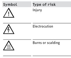
Symbols, type of risk
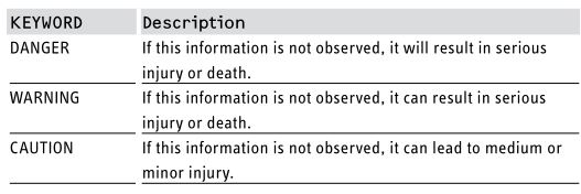
Keywords
Other symbols in this document
![]()
NoteNotes are bordered by horizontal lines above and below the text. General information is identified by the symbolshown on the left.
- Read these notes carefully.

- This symbol indicates that you have to do something. The action you need to take is described step by step.
Safety
Observe the following safety information and regulations.Operate the water heater only when fully installed and with all safety equipment fitted.
Intended use
The water heater is intended for heating domestic hot water and can supply several draw-off points.Any other use beyond that described shall be deemed inappropriate, and may void the manufacturer’s warranty.Observation of these instructions is also part of the correct use of this water heater.
Safety precautions
![]()
DANGER: InjuryPlease read and follow these instructions. Failure to follow these instructions could result in serious personal injury or death.
![]()
Damage to the water heater and the environmentThe water heater must be installed by a licensed electrician and plumber. The installation must comply with all national, state and local plumbing and electric codes. Service of the water heater must be performed by qualified service technicians.
![]()
DANGER: ElectrocutionBefore proceeding with any installation, adjustment, alteration, or service of the water heater, all circuit breaker switches servicing the water heater must be turned off. Make sure that nobody can activate the breaker in the distribution panel during your service work on the water heater.
![]()
DANGER: ElectrocutionThe water heater must be properly grounded. Failure to electrically ground the product could result in serious personal injury or death.
![]()
DANGER: ElectrocutionNever open the water heater cover unless the electricity servicing the water heater is turned off.
![]()
DANGER: BurnsWater temperatures over 125 °F (52 °C) can cause severe burns instantly or death from scalding. A hot water scalding potential exists if the thermostat on the water heater is set too high. Households with small children, disabled or elderly persons may require that the thermostat be set at 113 °F (45 °C) or lower to prevent possible injury from hot water.
![]()
WARNING: InjuryWhere children or persons with limited physical, sensory or mental capabilities are to be allowed to control this water heater, ensure that this will only happen under supervision or after appropriate instructions by a person responsible for their safety.Children should be supervised to ensure that they never play with the water heater.
Test symbols
See the type label on the water heater.
Licenses / certificates
– UL (USA) Std. 499: 2014 Ed.14– CSA (Canada) Std. CSA C22.2#88 issue:1958/09/01 (R2013)
Functional characteristics
CE/CES/CERO models are three-phase instantaneous electric water heaters, intended for commercial use, permanently wired in Delta or Wye configuration. Each series has models with power output ranging from 12–144 kW.
CE models feature adjustable temperature output with a range of 60–185 °F (16–85 °C), user-adjustable in one degree increments (°F or °C) via a push button switch (12).
CES models limit the output temperature according to OSHA requirements to a maximum of 90 °F (32 °C). They are factory set at a fixed temperature of 85 °F (29 °C).
CERO models have the same temperature adjustment range as CE models, but are designed for caustic liquids like salt water. To avoid corrosion, titanium elements (1) are used instead of the standard incoloy elements (1) found in CE and CES models.
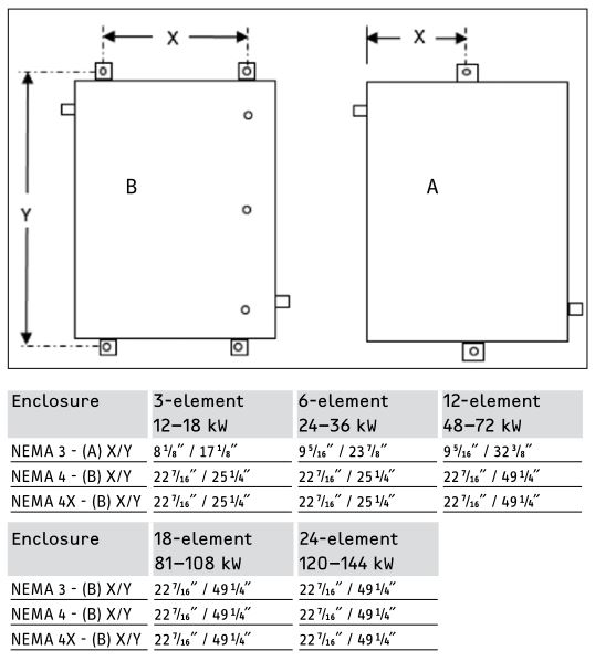
CE/CES/CERO 12–18 kW models contain 3 heating elements, 24–36 kW models contain 6 heating elements, 48–72 kW models contain 12 heating elements, 81–108 kW models contain 18 heating elements, and 120–144 kW models contain 24 heating elements. The elements used in different configurations are for 208, 240, 277, and 288 V.
CE/CES/CERO models are available in a NEMA 3 (standard), a NEMA 4 (optional), or a NEMA 4X (optional) enclosure.
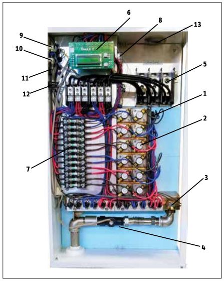
- Element
- Individual element thermostat/safety cut-off
- Pressure sensor switch
- Flow sensor
- Terminal block
- Electronic board PCB
- Fuse box
- Transformer
- Power indicator light
- On/off indicator light
- On/off switch
- Temperature set switch
- Wire support
The heater’s outgoing water temperature is controlled with an electronic board (6) receiving sensor information from the flow sensor (4), and an NTC sensor placed to detect incoming and outgoing water temperatures. The element turns on once the flow sensor detects a flow rate at or above the minimum activation rate. The board calculates the necessary heating capacity, depending on required temperature rise and flow rate.
Safety is provided by an individual thermostat/safety cut-off (2) for each element, designed to avoid excessive heat buildup. A pressure sensor switch (3) is installed in the first chamber to eliminate any possibility of dry firing. Each element circuit is individually fused. The fuses are located in the fuse box (7).
In order to avoid latent heat buildup, the unit has an electronically controlled delay timer that delays the activation of the heating element slightly. This feature allows air to be purged from the system before the element arrangement is activated to heat, and eliminates scalding risk. Beside the electronic delay, the board has no additional safety functions.
The display monitor shows the set point temperature, the actual outgoing water temperature, the flow rate and the heating rate. It is possible to change the units from °F / gpm to °C /l/min.
Safety is provided by a pressure relief valve with a 150 psi setting.
Troubleshooting
Before troubleshooting, check the following items:
- Is the water pressure more than 3 psi (0.21 bar)?
- Is the electric supply a:
- Wye (4 wires + ground) or
- Delta (three wires + ground)?
- Does the electric supply match the voltage and configuration designation shown on the unit nameplate?
- If the heater fails to maintain the desired temperature, check the flow rate according to the table. See 10.6, “CE/CES/CERO Temperature rise”, pg. 26.
The following items are required for testing to diagnose a possible failure:
Continuity tester, 600 V voltage meter, amp and Ohm meter.
Use the following steps for diagnosis:
- Turn off the power supply to the heater.Caution: follow all safety precautions in 2.2, “Safety precautions”, pg. 3.
- Turn off the heater on/off switch (12).
- Open the heater enclosure.
- Check for any loose connections, and properly operating breakers.
- Purge the heater to cool down the heater and to reset the electronic thermostat function.
- Turn the main breaker back on. Turn on the heater on/off switch (12). For resistivity test turn the breaker off and check voltage just in case.
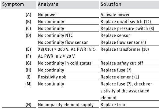
Fault table
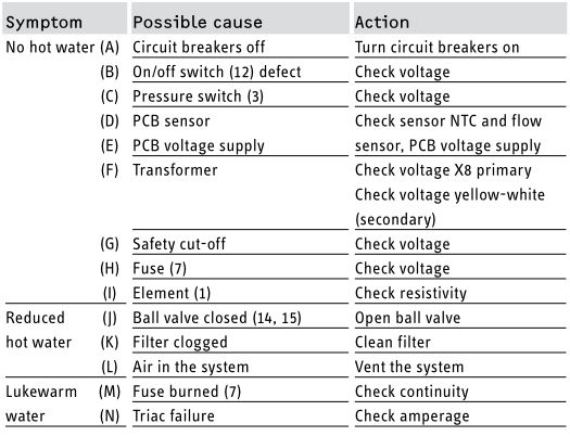
Solutions based on symptoms in fault table
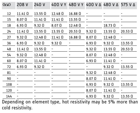
Cold element resistivity by heater type (in Ohms)
INSTALLATION
Mounting the water heater
![]()
CAUTION: InjuryHot water outlet pipes leaving unit can be hot to the touch. Insulation must be used for hot water pipes below 36˝ (0.9 m) due to burn risk to children.
![]()
NOTICE:This unit should not be installed in a location where it may be exposed to temperatures less than 36 °F (2 °C). If the unit may be subject to freezing temperatures all water must be drained from the unit. Failure to comply with this instruction voids all warranties. The unit should be located in an area where water leakage from the unit or connections will not result in damage to the area adjacent to the unit. If such a location cannot be avoided it is recommended that a drain pan be installed under the unit.
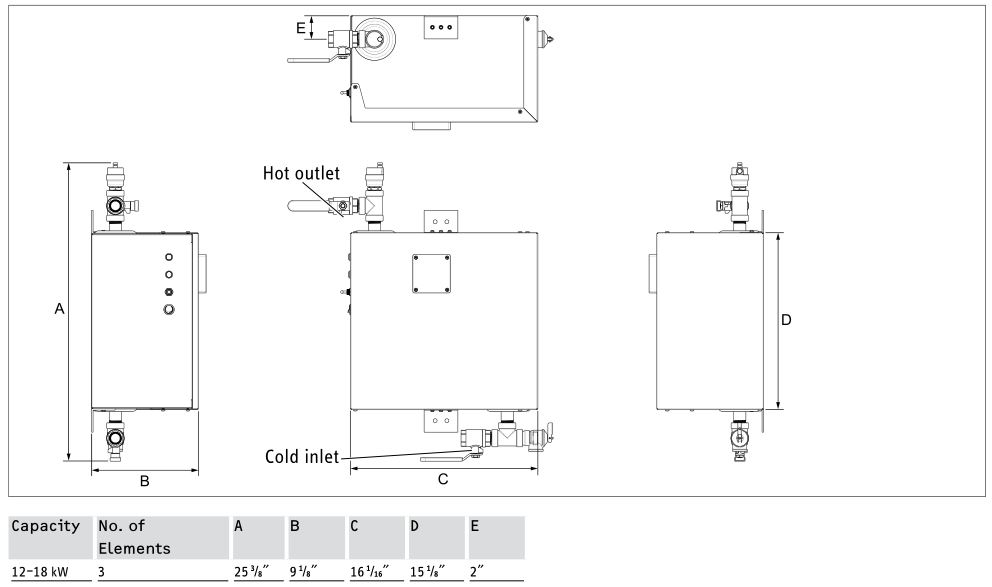
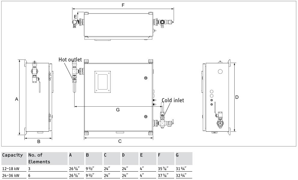
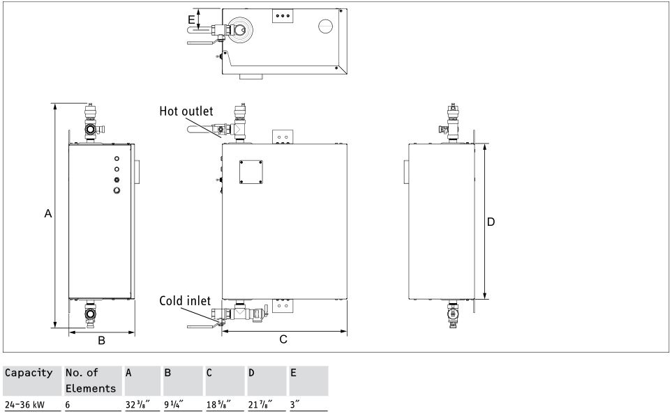
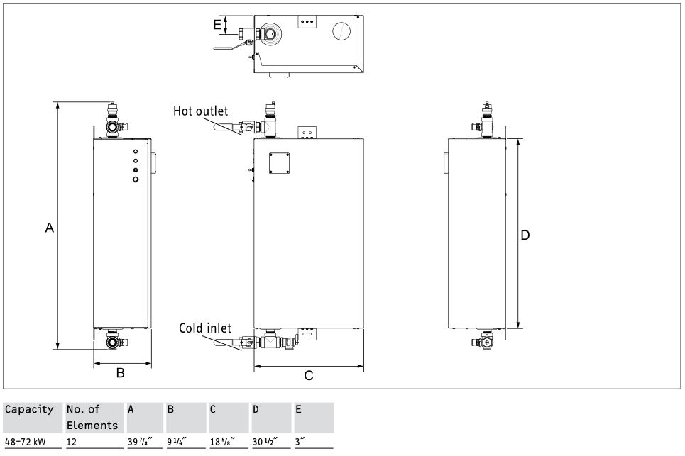
ApplicationBefore mounting, double check that the correct voltage the unit requires matches the voltage of the local power supply. The voltage and configuration (Wye or Delta) are declared on the nameplate. Make sure that the supply wire size corresponds to the heater capacity and wire run according to NEC. Installation carried out by a licensed electrician will ensure this. The hot water supply includes an air vent. The incoming water supply is equipped with a pre-installed pressure relief valve. For water supply line positions, see section 10.4, “Dimension drawings”, pg. 11.
Mounting
- Install the water heater as close as possible to the main hot water draw off points.
- Keep a minimum of 5˝ (127 mm) clearance on all sides for service.
- NEMA 3 enclosures require a minimum clearance of 20˝ (510 mm) on the front side to allow the hinged cover to be fully opened.
- If there is a drain tube connected to the pressure relief valve, make sure that the drain water is not blocked by anything.
Enclosure dimensions, excluding plumbing fittings

Mounting screw positions
Water connections
![]() NOTICE:Excessive heat from soldering on copper pipes near the heater may cause damage.
NOTICE:Excessive heat from soldering on copper pipes near the heater may cause damage.
![]()
NOTICE:Hard water or water with a high mineral count may damage the unit. Damage to the unit caused by scale or a high mineral count is not covered under the warranty.
Venting the air
- Before the heater is connected to the water supply, make sure that the water supply is flushed first to ensure it is free from any scale and dirt. The water pressure needs to be less than 145 psi (10 bar).
- If the water pressure exceeds 145 psi (10 bar), install a pressure reducing valve in the cold water pipework. Cold water supply (inlet) is located on the bottom right.
- Before the heater is connected to the electric supply, make sure that the water supply line is flushed for 3 minutes minimum to vent any air pockets out of the tubing system.
- Open the service screw on the vent valve to release the air.
- Open and close the ball valve on the cold water supply side several times to release any air pockets from the heater.
- Once the air is released, close the screw on the vent valve.
Leakage check
Once all plumbing work is done, check for leaks. If necessary, take corrective action.
Electrical connection
Safety
![]()
DANGER: ElectrocutionBefore proceeding with any installation, adjustment, alteration, or service of the water heater, all circuit breaker switches servicing the appliance must be turned off. Make sure that nobody can activate the breaker in the distribution panel during your service work on the appliance.
![]()
DANGER: ElectrocutionThe appliance must be properly grounded. Failure to electrically ground the product could result in serious personal injury or death.
Electric supply
Check the electric supply infrastructure:
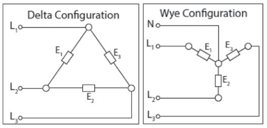
For Delta configuration, a three-phase wire and a ground are supplied. For a Wye configuration, a three-phase wire, a neutral, and a ground are supplied. The configuration and voltage are declared on the unit name plate on the enclosure front type plate.
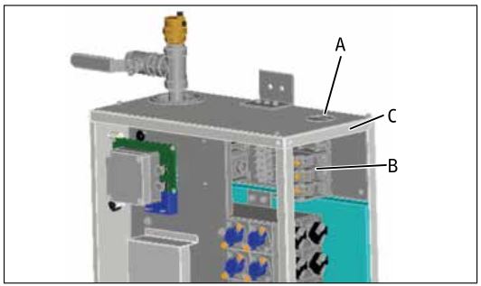
- Feed the wire through the knockout (A) using a Romex clamp for strain relief.
- Connect the live wires to the contactor (B).
- Pull the ground wire into the ground terminal (C).
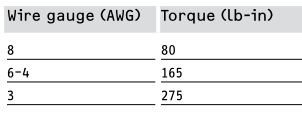
Terminal block torque
To tighten wire to the terminal block, use the proper torque value according to NEC:
The water heater should be connected to a properly grounded dedicated branch circuit of proper voltage rating. In installations with several CE/CES/CERO water heaters, each unit requires a separate circuit with wire sizes according to NEC.
Commissioning
- Close the front cover before the electric supply is turned on.
- Before the heater is activated by switching the electric supply on, run hot water via a hot water faucet for a minimum of 3 minutes to purge all air from the system.

- Turn on the circuit breaker.
- Turn on the heater via the on/off switch.
- Check the water temperature after several minutes of operation.
- Explain the end user how the heater operates.
- Make the end user aware that hot water can cause injures if it is more than 125 °F (52 °C).
- Draw special attention to the safety information.
- Hand over the operating manual to the end user.

Maintenance
![]()
DANGER: ElectrocutionBefore proceeding with any installation, adjustment, alteration, or service of the appliance, all circuit breaker switches servicing the appliance must be turned off. Make sure that nobody can activate the breaker in the distribution panel during your service work on the appliance.
Stiebel Eltron water heaters are designed for a very long service life. Actual life expectancy depends on water quality and use. To ensure consistent water flow, remove scale build up on the faucet or any connected fixtures.
Technical data
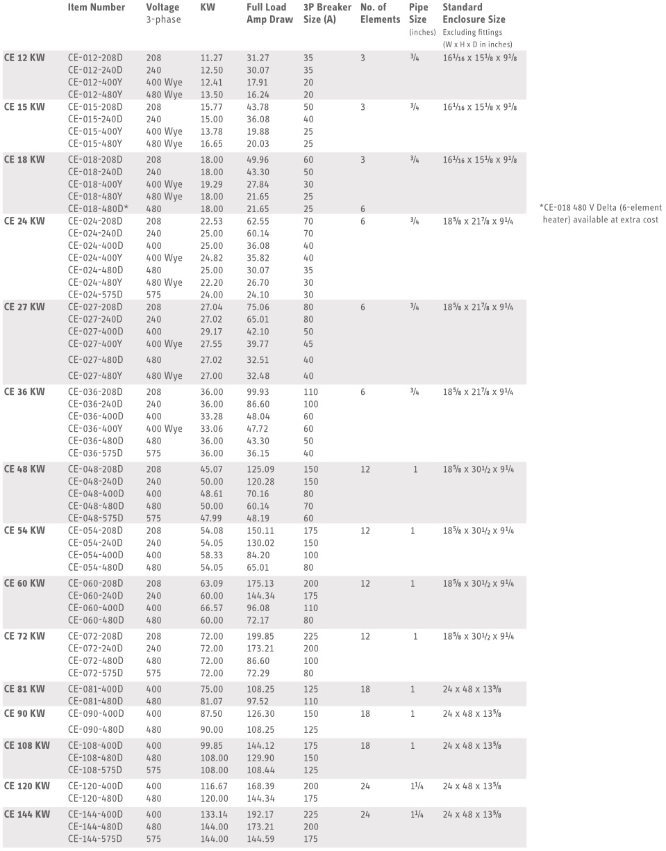
Technical data – CE series
Technical data – CES series

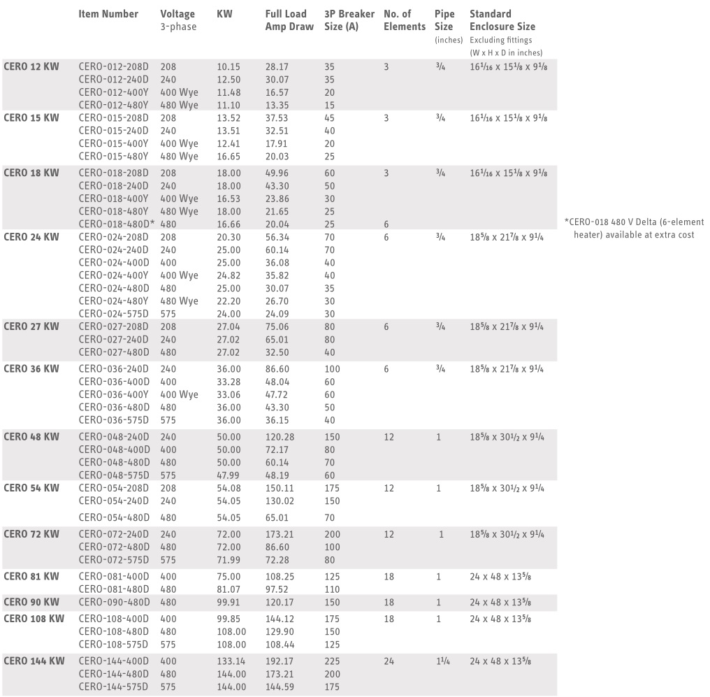
Technical data – CERO series
Dimension drawings
CE/CES/CERO 12–18, NEMA 3 enclosure
CE/CES/CERO 12–36, NEMA 4/4X enclosure
CE/CES/CERO 24–36, NEMA 3 enclosure
CE/CES/CERO 48–72, NEMA 3 enclosure
CE/CES/CERO 81–144, NEMA 3 enclosure / CE/CES/CERO 48–144, NEMA 4/4X enclosure

Wiring Diagrams
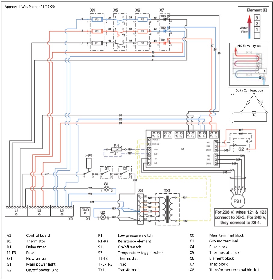
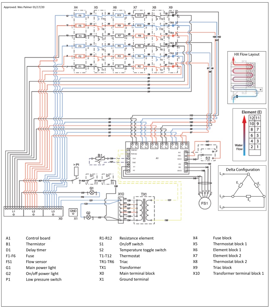
CE/CES/CERO 12–18, 208 V & 240 V Delta wiring diagram
This diagram is valid for: CE/CES/CERO 12 208/240 V, CE/CES/CERO 15 208/240 V, CE/CES/CERO 18 208/240 V
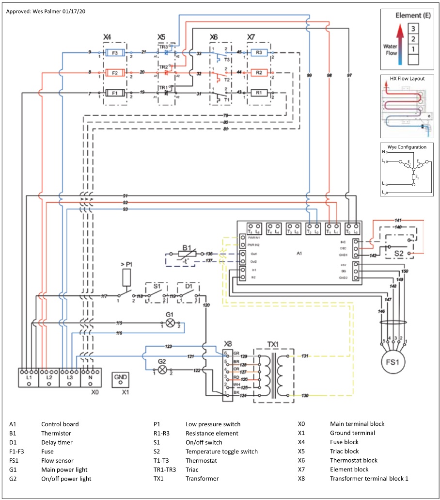
CE/CES/CERO 12–18 400 & 480 V Wye wiring diagram
This diagram is valid for: CE/CES/CERO 12 400/480 V Wye, CE/CES/CERO 15 400/480 V Wye, & CE/CES/CERO 18 400/480 V Wye
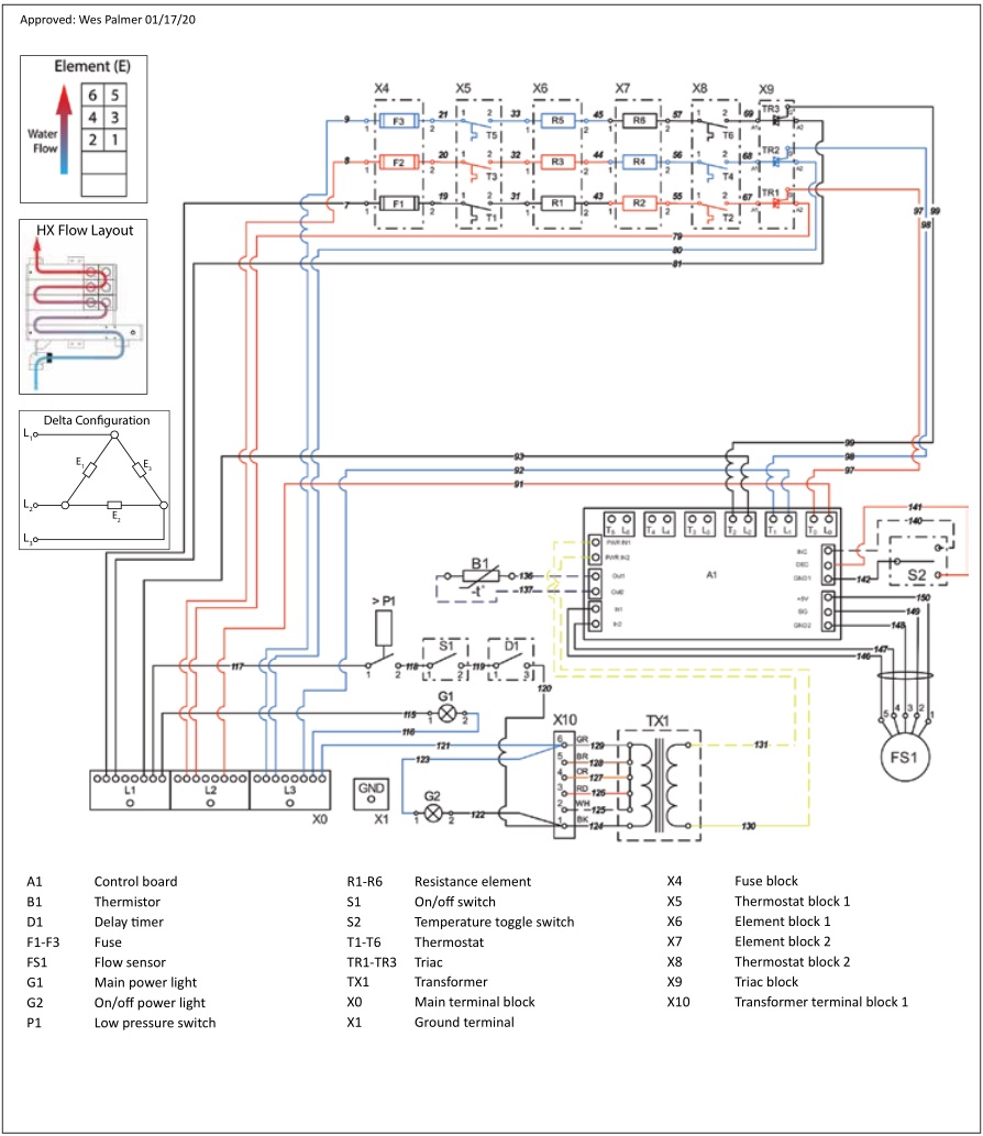
CE/CES/CERO 24–36, 208 V & 240 V Delta wiring diagram
This diagram is valid for: CE/CES/CERO 24 208/240 V, CE/CES/CERO 27 208/240 V, & CE/CES/CERO 36 208/240 V

CE/CES/CERO 24–36, 400 V & 480 V Delta wiring diagram
This diagram is valid for: CE/CES/CERO 24 400/480 V, CE/CES 27 400/480 V, CERO 27 480 V, & CE/CES/CERO 36 400/480 V
CE/CES/CERO 24, CE/CES/CERO 36 575 V Delta wiring diagram
This diagram is valid for: CE/CES/CERO 24 575 V, & CE/CES/CERO 36 575 V

CE/CES/CERO 48–72, 208 V & 240 V Delta wiring diagram
This diagram is valid for: CE/CES 48 208/240 V, CERO 48 240 V, CE/CES 54 208/240 V, CERO 54 240 V, CE/CES 60 208/240 V, CE/CES 72 208/240 V, & CERO 72 240 V
CE/CES/CERO 48–72, 400 V & 480 V Delta wiring diagram
This diagram is valid for: CE/CES/CERO 48 400/480 V, CE/CES 54 400/480 V, CERO 54 480 V, CE/CES 60 400/480V, CE/CES 72 480 V, & CERO 72 400/480 V
CE/CES/CERO 48, CE/CES/CERO 72 575 V Delta wiring diagram
This diagram is valid for: CE/CES/CERO 48 575 V, CE/CES/CERO 72 575 V

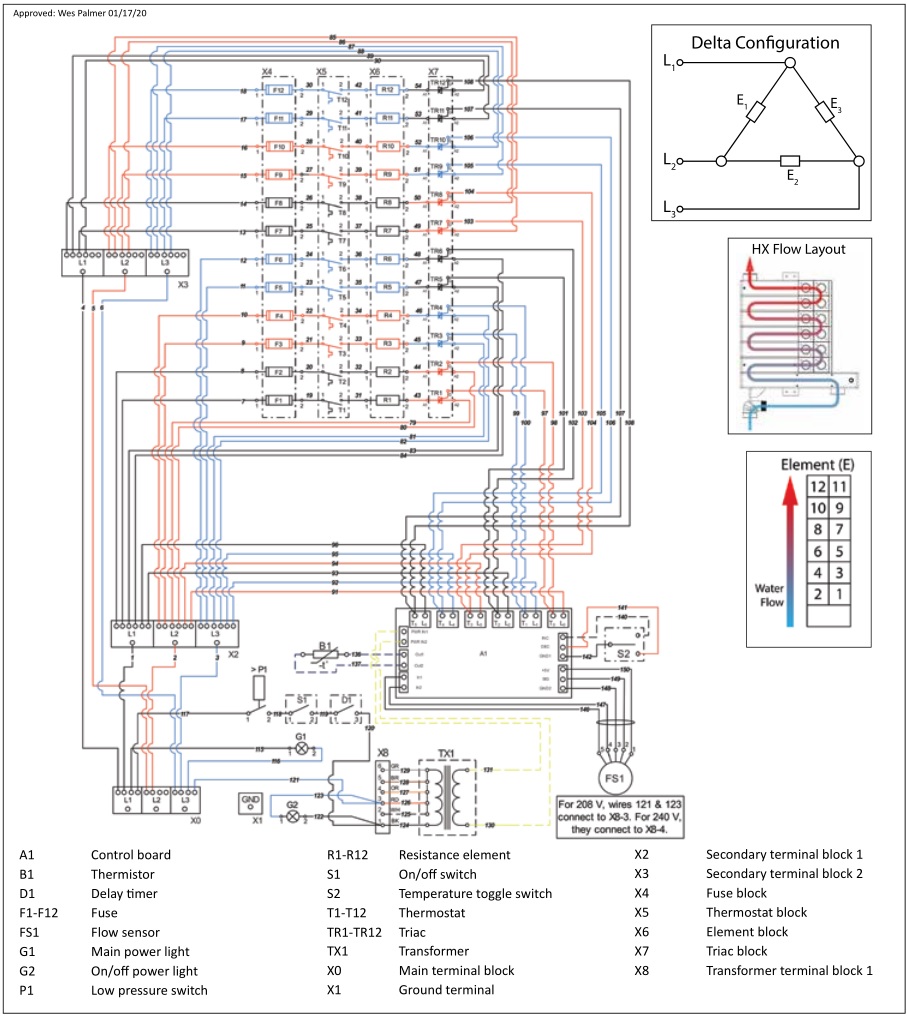
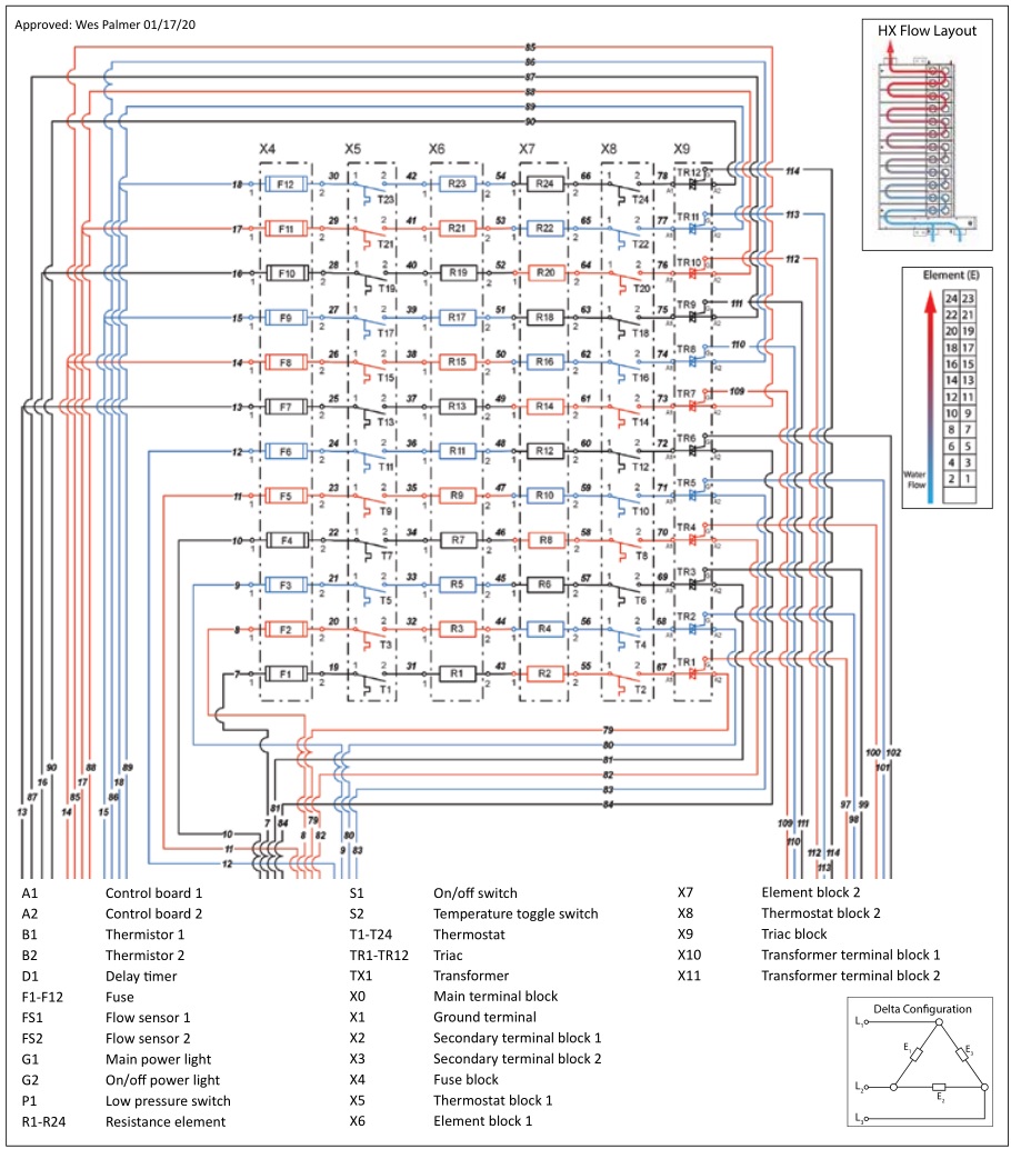
CE/CES/CERO 120, CE/CES/CERO 144 400 V & 480 V Delta wiring diagram (page 1)
This diagram is valid for: CE/CES/CERO 120 400/480 V, CE/CES/CERO 144 400/480 V
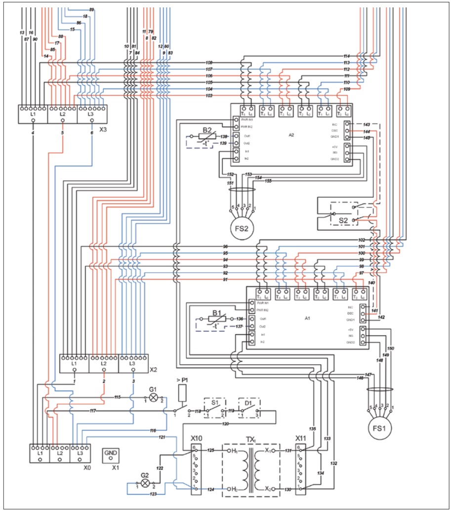
CE/CES/CERO 120, CE/CES/CERO 144 400 V & 480 V Delta wiring diagram (page 2)
This diagram is valid for: CE/CES/CERO 120 400/480 V, CE/CES/CERO 144 400/480 V

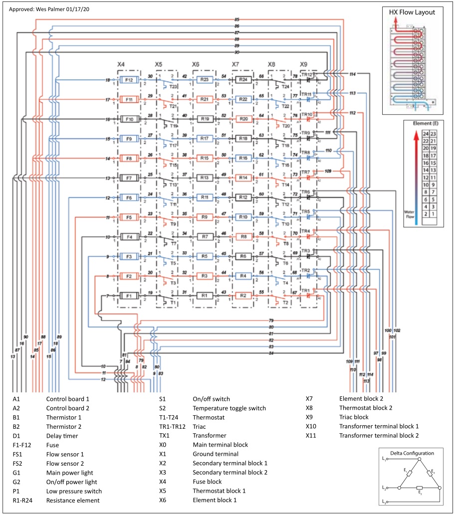
CE/CES/CERO 144 575 V Delta wiring diagram (page 1)
This diagram is valid for: CE/CES/CERO 144 575 V
CE/CES/CERO 144 575 V Delta wiring diagram (page 2)
This diagram is valid for: CE/CES/CERO 144 575 V
CE/CES/CERO Temperature rise

Spare parts and service advice
![]()
DANGER: ElectrocutionBefore proceeding with any installation, adjustment, alteration, or service of the appliance all circuit breaker, switches servicing the appliance must be turned off. Make sure that nobody can activate the breaker in the distribution panel during your service work on the appliance.
![]()
DANGER: BurnsWater temperatures over 125 °F (52 °C) can cause severe burns instantly or death from scalding. A scalding potential risk exists on any connected tap or fixture and on the surface of the heat exchanger during service. Before opening the housing for service, ensure the on/off switch is in the “off” position. Flush cold water through the heater for several minutes. The ball valves need to be completely open.
Pressure switchCheck the water supply pressure. The heater requires 3 psi (0.21 bar) to activate the pressure switch. Check for continuity across the switch contact. If the switch is not closed and the pressure is more than 3 psi (0.21 bar), the mechanical portion of the pressure switch may clogged with debris.
Thermostat/safety cut-offThe thermal safety cut-off also has a permanent cut-off safety function in case of an emergency caused by overheating. The fuse side of the thermostat is designed to be destroyed by extreme heat. Should this occur, the individual thermostat/safety cut-off will need to be replaced.
If the thermal cut-off was not overheated, it will have continuity.
The thermal cut-off condition is determined by a continuity check after power is off and cold water has been run through the heater.
If the cut-off has no continuity, it should be replaced . Make sure that the water is drained, and the power supply is off. Remove the wires to the cut off with a flathead screwdriver. Remove the Allen screw with a 1/4˝ T-handle Allen wrench. Remove the thermal cut-off and replace it with an identical spare part item, e.g. L125 T puts out 125 °F hot water. Do not mix them with any other temperature designated item. Replace the cut off clips. Make sure that the concave end is down to create a tight seal. Reinsert the Allen screws. Reattach the wire. Make sure that the wire screws are tightened fully.
ElementIf the heater display shows active heating and there is still lukewarm water at the desired flow rate, a failed element may be the cause.
- Disconnect the heater from the power supply.
- Check each element with an Ohm meter for correct reading. See 4.3, “Cold element resistivity by heater type (in Ohms)”, pg. 5, to identify the element resistivity according to the heater name plate and wattage. If the element reads 0 Ohm or the meter flickers, the element needs to be replaced.
- For replacing the identified bad element, use a Phillips screwdriver to remove the wire. If there is more than one failed element, mark the wires of the associated elements.
- Close the ball valves and drain the heater.
- To remove the element from the heat exchanger socket, use a 1 1/2˝ socket wrench spanner. If the failed element looks like it is split from the inside, this can be caused by air contamination during heating.
- Insert the new element, being sure that the replacement element has a factory provided O-ring in place.
- Tighten the element. Make sure that it is not overly tight. This will ruin the O-ring sealing.
- After all elements are replaced, check for leaks by opening the ball valves and running water through the heater.
- Reattach the wires to the element.
- Turn on the power supply.
- Turn on the on/off power switch.
Transformer
- Disconnect the heater from the power supply.
- Check for continuity on the fuse FLM1-1/4 to be sure the problem is not just a transformer fuse.
- Replace wire from the transformer distribution block. Make sure to mark the wire to the desired port.
- Loosen the mounting screws in the corner of the transformer to the support bar.
- Replace the transformer and rewire the spare part transformer as before.
Pressure switchIt is possible for the pressure switch to be become so blocked with residue or dirt that it does not function and allow the heater to turn on.
- Disconnect the heater from the power supply.
- Check for continuity across the poles of the switch with water pressure on the heater. The water pressure needs to be more than 3 psi (0.21 bar). If there is continuity, the pressure switch is not the cause.
- If there is no continuity, drain the water from the heater and remove the wires from the switch. Mark the wires with the switch pole designation. Pole nb. 1 needs to be connected to the transformer.
- Remove the switch using an open-end wrench.
- Check for water leaks.
- Rewire the switch.
Triac failureIf there is lukewarm water in steady state status of the heater, check the ampacity of each supply wire from the element contact to the triac supply. If there is no ampacity from the triac supply to the element, replace the triac.For triac replacement, make sure that enough heat transfer paste is applied between the cooling plate and the triac.
Indicator light
- Disconnect the heater from the power supply.
- Clip the wires to the light. Pop out the light socket out of the hole in the enclosure.
- Install the spare part light. Rewire the spare part light.
Element fuses
- Disconnect the heater from the power supply.
- Remove the failed fuses from the fuse holder.
- Replace the fuse. For elements larger than 6000 W at 240 V rating, use MDL 35 type fuse. For smaller elements use part number KLK 30.
Warranty
Subject to the terms and conditions set forth in this limited warranty, Stiebel Eltron, Inc. (the “Manufacturer”) hereby warrants to the original purchaser (the “Owner”) that each Tankless Electric Commercial Water Heater (the “Heater”) shall not (i) leak due to defects in the Manufacturer’s materials or workmanship for a period of six (6) years from the date of purchase or (ii) fail due to defects in the Manufacturer’s materials or workmanship for a period of two (2) years from the date of purchase. As Owner’s sole and exclusive remedy for breach of the above warranty, Manufacturer shall, at the Manufacturer’s discretion, send replacement parts for local repair; retrieve the unit for factory repair, or replace the defective Heater with a replacement unit with comparable operating features. Manufacturer’s maximum liability under all circumstances shall be limited to the Owner’s purchase price for the Heater.
This limited warranty shall be the exclusive warranty made by the Manufacturer and is made in lieu of all other warranties, express or implied, whether written or oral, including, but not limited to warranties of merchantability and fitness for a particular purpose. Manufacturer shall not be liable for incidental, consequential or contingent damages or expenses arising directly or indirectly from any defect in the Heater or the use of the Heater. Manufacturer shall not be liable for any water damage or other damage to property of Owner arising, directly or indirectly, from any defect in the Heater or the use of the Heater. Manufacturer alone is authorized to make all warranties on Manufacturer’s behalf and no statement, warranty or guarantee made by any other party shall be binding on Manufacturer.
Manufacturer shall not be liable for any damage whatsoever relating to or caused by:
- any misuse or neglect of the Heater, any accident to the Heater, any alteration of the Heater, or any other unintended use;
- acts of God and circumstances over which Manufacturer has no control; The installation, electrical connection and first operation of this appliance should be carried out by a qualified installer. The company does not accept liability for failure of any goods supplied which have not been installed and operated in accordance with the manufacturer‘s instructions.
- installation of the Heater other than as directed by Manufacturer and other than in accordance with applicable building codes;
- failure to maintain the Heater or to operate the Heater in accordance with the Manufacturer’s specifications;
- operation of the Heater under fluctuating water pressure or in the event the Heater is supplied with non-potable water, for any duration;
- improper installation and/or improper materials used by any installer and not relating to defects in parts or workmanship of Manufacturer;
- moving the Heater from its original place of installation;
- exposure to freezing conditions;
- water quality issues such as corrosive water, hard water, and water contaminated with pollutants or additives;
Should owner wish to return the Heater to manufacturer for repair or replacement under this warranty, Owner must first secure written authorization from Manufacturer. Owner shall demonstrate proof of purchase, including a purchase date, and shall be responsible for all removal and transportation costs. If Owner cannot demonstrate a purchase date this warranty shall be limited to the period beginning from the date of manufacture. Manufacturer reserves the right to deny warranty coverage upon Manufacturer’s examination of Heater. This warranty is restricted to the Owner and cannot be assigned.
Some States and Provinces do not allow the exclusion or limitation of certain warranties. In such cases, the limitations set forth herein may not apply to the Owner. In such cases this warranty shall be limited to the shortest period and lowest damage amounts allowed by law. This warranty gives you specific legal rights and you may also have other rights which vary from State to State or Province to Province.
Owner shall be responsible for all labor and other charges incurred in the removal or repair of the Heater in the field. Please also note that the Heater must be installed in such a manner that if any leak does occur, the flow of water from any leak will not damage the area in which it is installed.
Environment and recycling
Please help us to protect the environment by disposing of the packaging in accordance with the national regulations for waste processing.
This Warranty is valid for U.S.A. & Canada only. Warranties may vary by country. Please consult your local Stiebel Eltron Representative for the Warranty for your country.
TANKLESS, Inc.A Stiebel Eltron Company2060 Whitfield Park Ave. | Sarasota, FL 34243Tel. 800.TANKLESS (800.826.5537) | Fax 941.755.6529[email protected]
STIEBEL ELTRON, Inc.17 West Street | West Hatfield MA 01088Tel. 413.247.3380 | Fax 413.247.3369[email protected]www.stiebel-eltron-usa.com
Subject to errors and technical changes!
![]()
Stieble Eltron CE/CES/CERO Series Electronically Controlled Instantaneous Water Heater User Manual – Stieble Eltron CE/CES/CERO Series Electronically Controlled Instantaneous Water Heater User Manual –
[xyz-ips snippet=”download-snippet”]