![]() SPXSH440
SPXSH440
 Quick Start Guide
 PRECAUTIONS
Disconnect the vehicle’s negative battery cable before making any wire connections.Protect all vehicle surfaces with tape or plastic.Do not install components in any location that will hinder vehicle operation, such as steering wheel, gearshift, airbags, hazard switch.Bundle cables and harnesses with electrical tape or wire ties to prevent them from interfering with moving parts.Never attempt to disassemble or modify the product. Otherwise, an accident, fire, or electric shock may result.Exposed wires must be insulated with electrical tape. Otherwise, a short circuit, fire, or electric shock may result.To prevent damage to the vehicle, confine the locations of hoses, electrical wiring, and the fuel tank prior to drilling holes to install this product.When it is necessary to replace the fuse, always use a fuse of the correct rating (number of amperes). The use of fuses with higher amperage ratings may cause a fire.
Overview
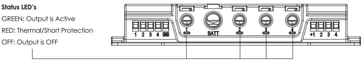
SwitchHub is a solid-state relay hub with 4 independent outputs. One 40 amp output and three 20 amp outputs, for a combined total of I 00 amps continuous output. Each output can be independently triggered by a positive or negative trigger. Outputs can be combined for applications that require more than a single output amperage rating. Each output has automatic thermal overload protection with LED status indicators.
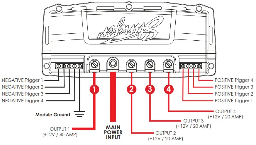
Main Power Input – Connect to Battery Positive. An inline fuse should be used if the power source is over 18″ away.Module Ground – Connect to Chassis GroundNEGATIVE Triggers 1-4 – When a Negative(-) signal is applied, corresponding OUTPUT (1-4) will activate.POSITIVE Triggers 1-4 – When a Positive (+) signal is applied, corresponding OUTPUT (1-4) will activate.Power Outputs 1-4 – When triggered, output + 12VExamples: When Negative Trigger 3 is grounded, OUTPUT 3 will output+ 12VWhen Positive Triggers 1&.2 receive +12V, OUTPUTS 1&2 will output+ 12V
A momentary push-button switch that outputs Ground(-12V) when pressed, is connected to Negative Trigger 1. OUTPUT 1 is connected to +12V of horns.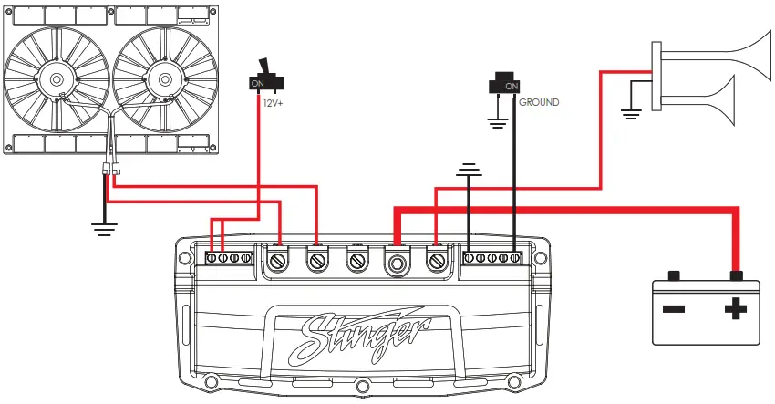
A toggle switch that outputs + 12V when ON is connected to Positive Triggers 3 and 4. OUTPUTS 3 and 4 are connected to + 12V electric fans.
The four positive triggers coming from the SPXM 1 are con need to Positive Triggers 1-4. OUTPUTS 1-4 are connected to +12V of various accessories. 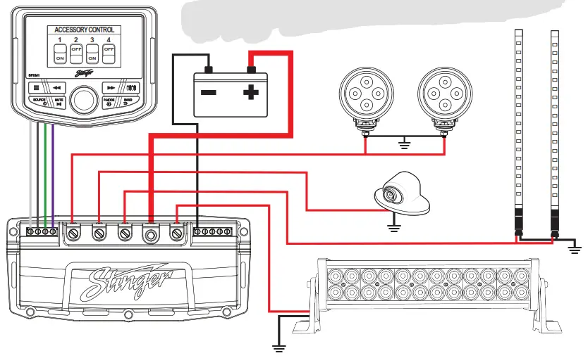
LIMITED WARRANTY:
Stinger warrants this product to be free of defects in materials and workmanship for a period of one ( 1) years from the original date of purchase. This warranty is not transferable and applies only to the original purchaser from an authorized Stinger dealer in the United States of America only. Should service be necessary under this warranty for any reason due to manufacturing defect or malfunction, Stinger will (at its discretion), repair or replace the defective product with the new or remanufactured product at no charge. Damage caused by the following is not covered under warranty: accident, misuse, abuse, product modification or neglect, failure to fol low installation instructions, unauthorized repair attempts, misrepresentations by the seller. This warranty does notcover incidental or consequential damages and does not cover the cost of removing or reinstalling the unit(s). Cosmetic damage due to accident or normal wear and tear is not covered under warranty.INTERNATIONAL WARRANTIES: Products purchased outside the United States of America are covered only by that country’s Authorized Stinger reseller and not by Stinger. Consumers needing service or warranty information for these products must contact that country’s reseller for information.
Stinger is a Power Brand of AAMP Global15500 LightwaveClearwater, Florida 337 60P: 888-228-5560www.stingerelectronics.com© 2020 Stinger
Technical Support:Phone: 727-592-5991Email: [email protected]Chat: stingerelectronics.com
[xyz-ips snippet=”download-snippet”]