![]() ST1 Instructions
ST1 Instructions
ST1 TROUBLESHOOTING
If the following faults and symptoms arise, the relevant component is replaced directly.
MOTOR
- The following motor problems are shown on the display as faults: ICCURR, HEAT, OVERHEAT, HALL, CURR, Faceless, BRAKE, Block, and TMM (without riding the bike)
- The following symptoms indicate that a technical fault has occurred in the motor: Motor falters during travel, the motor produces mechanical noises, motor locks.
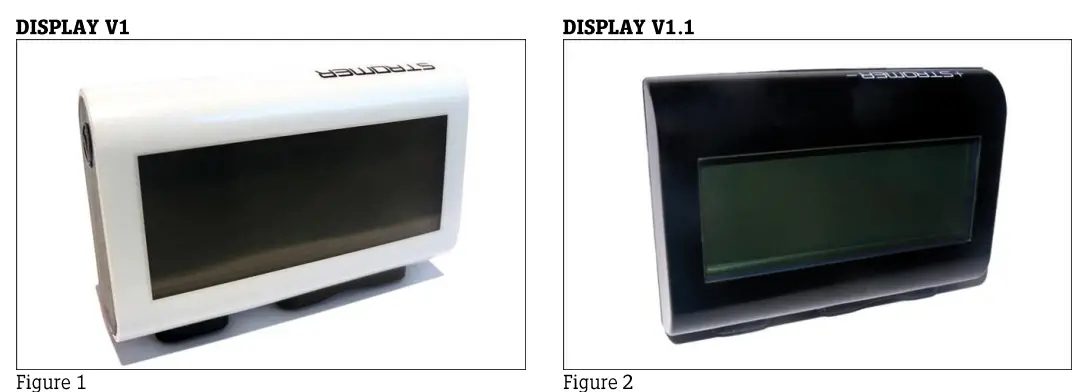
DISPLAY
- For display faults, replace the display with one in the latest version
- Currently, the latest version is 0.88 (Use the code 2000 when requesting this version)
- Broken display clamps are replaced individually
REAR COGS
- For the following faults, we recommend replacement of the rear cogs: gears perform poorly and loud noises are produced
CHARGER
- The charger is completely replaced for the following faults:
- The charger does not charge (fuse is OK)
- The ventilation fan is not working or is making a noise
- The charger cannot be switched on (LEDs on the charger do not light up)
FAULT NO_COM/NO_BATT (VISIBLE ON DISPLAY):
- Check the battery with a voltmeter. If the battery voltage is 32 V or more, proceed to Step 2.
- If the battery voltage is less than 32 V, the battery is deeply discharged.

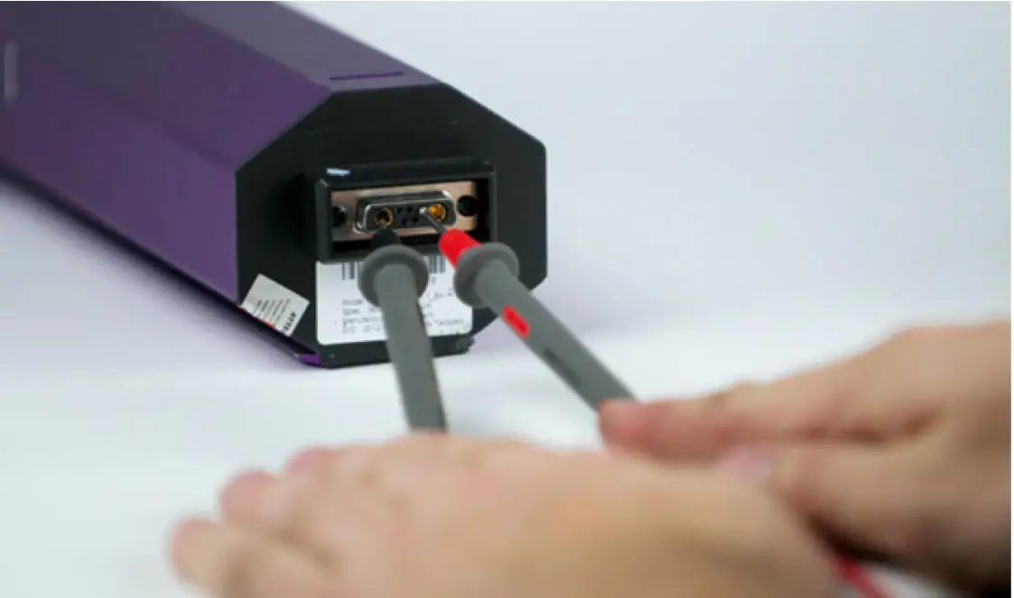
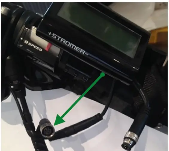
- Separate the power cables under the left chainstay and check the battery voltage at the pins shown in the photo. If the voltage obtained agrees with the battery voltage and the display continues to show NO_COM/NO_BATT, proceed to Step 3.
- If the voltage obtained is less than the battery voltage (+/- 1 V difference), remove the battery cover and check the connections. If the difference remains, check the voltage directly at the wicket cable. Using the voltage obtained at the wicket cable, identify whether the power cable or the wicket cable needs to be replaced.
- Separate the TMM sensor cable under the left chainstay (3-pole cable). If the NOLCOM/NO_BATT fault message disappears from the display, replace the TMM sensor and its cable.
- Connect a functioning display directly to the motor.If the fault message is still displayed, the motor must be replaced (continue at step 5). If the fault message disappears, connect the display on the handlebar to the display cable. If the fault message disappears, the display must be replaced. If the fault message is still present, the display cable is faulty
- The fault could be narrowed down to the motor.
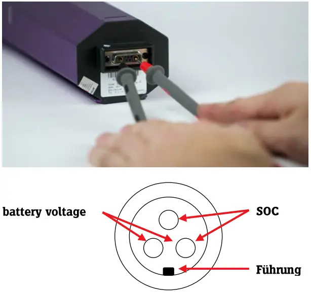
SOC-MEASUREMENT
Check the Battery Management System for a fault caused by overvoltage as follows.
- The BMS must be activated before checking the SOC signal (State Of Charge). (By giving a boost charge to the battery for approx. 10 seconds or placing it in the Stromer).
- Measure the voltage of the SOC signal (negative terminal <=> SOC pin) using a voltmeter. Compare the value obtained with the table below. A variation of +/- 1 V is within the range of tolerance.
- If the value is outside this range of tolerance (+/- 1 V), the BMS is defective. In this case, the battery needs to be replaced.
10/11AH
| Display | U-Akku | U-SOC |
| 100% | 42V | 10V |
| 75% | 39.5V | 8V |
| 50% | 37.5V | 5V |
| 25% | 36V | 2V |
| 0% | 31V | OV |
14.5AH
| Display | U-Akku | U-soc |
| 100% | 42V | 10V |
| 75% | 39V | 8V |
| 50% | 37V | 5V |
| 25% | 35.5V | 2V |
| 0% | 33V | OV |
TMM-ANALYSIS
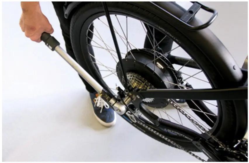
To analyze a TMM sensor there are several points to check:
- Visual checka connector on the left and right chainstayb Das Plastikgehdause des Sensors darf die Aussparung am Ausfallende nicht beriihren
- Functional testa Put the Stromer in a work stand and mount the TMM sensor manually (as picture a), the Stromer should work like this:I M25 alternating acceleration up to 25km/h or 15mphII M33 > 42km/h or 26mphIII P48 > 53km/h or 32mph
If the Stromer fails one of these criteria, the TMM sensor must be replaced.
PROGRAMMING
IMPORTANT!PLEASE OBSERVE THE FOLLOWING POINTS TO ENSURE THAT NO ADDITIONAL DEFECTS ARISE DURING PRO- GRAMMING:
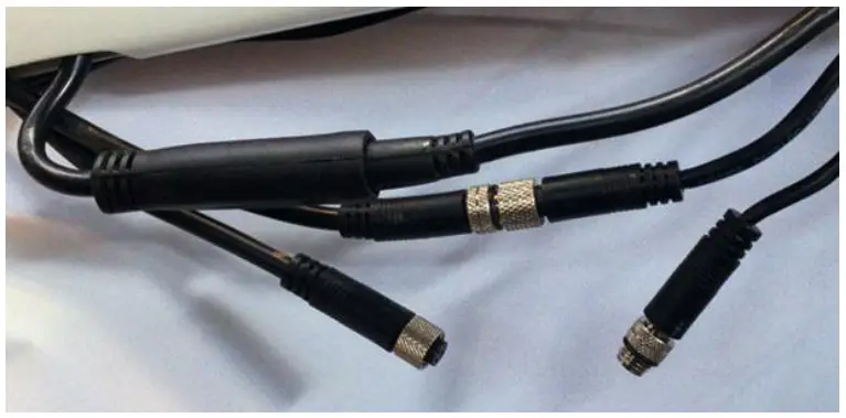
- Only use new adapters with a switch for programming cables (see figure 3).
Versions:IMPORTANT! Ensure that at least version 7.6 firmware is always installed in the V1.1 display.
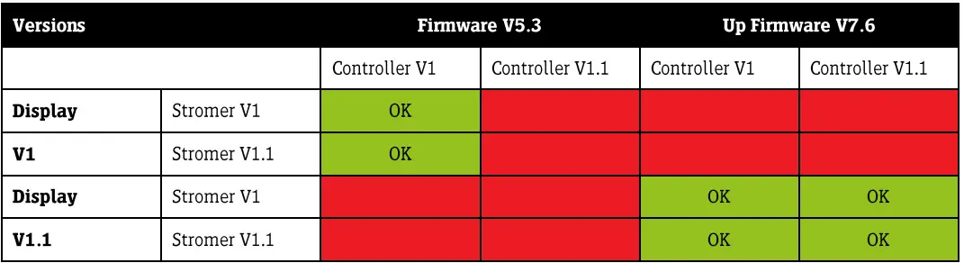
| STROMER V1Thémus logo on the top tube and head tube | STROMBER V1.1Stromer logo on the top tube and head tube | |
| Controller V12-pole power plug | Controller V1.13-pole power plug |
PROGRAMMING ELEMENTS

LOADING FIRMWARE
READING OUT THE FIRMWARE VERSION
- Connect the programming cable (with new adapter) to the PC and the Stromer
- Open «StromerV120530.exe»
IMPORTANT!If the Stromer is connected correctly to the PC, the firm-ware version will be shown in the top right-hand corner of the screen and the status dot will be green. If the Stromer is not connected correctly to the PC, the version number will not be displayed. The status dot will be red. In this case, the wrong COM port may have been selected (tab: System Configure). The number of the firmware version is displayed in color; however, the different colors are only significant from Version 7.6 upward.:

Blue: Stromer is working properly.Red: After re-loading the firmware with XC800_FLOAD.exe: the settings still have to be loaded.
LOADING FIRMWARE
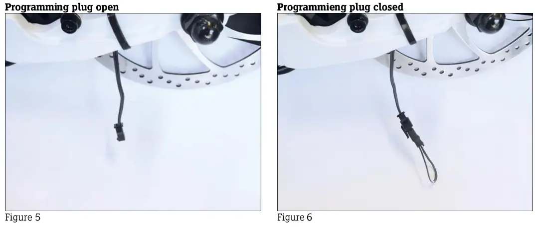
- Close the programming plug
- Connect the programming cable (with new adapter) to the PC and the Stromer
- Switch off the programming switch
- Switch on the programming switch
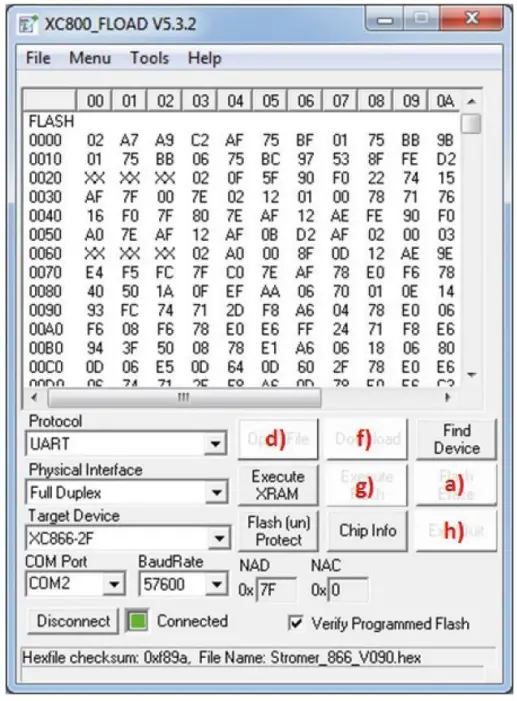
- Open «XC800_FLOAD.exe»
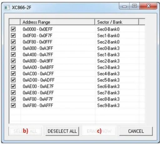
- Select target device: XC866-2F
- Verify Programmed Flash should be checked
- Select COM portIMPORTANT: A different COM port is used for each USB connection. Always use the same Stromer programming cable for same USB connection..
- Carry out the following commands in the sequence shown:a)«Flash Erase»b)«SELECT ALL»c)«ERASE NOW» the message «Flash Erase: SUCCESSd)» should now be displayed. If not, close the program and go back to Step 3. «Open File»e)Select & open «Stromer_866_V090.hex». When you first call this up after a new installation, you will need to navigate to the respective folder. For ex-ample: «C\Program Files (x86)\f)«Download» > A window should appear with the message «Download and Verification are success-Jul.»f)«Execute Flash» > Status will be red againh)«Exit/Quit»
- Open the programming plug (Figure 5). Before using the Stromer, the settings must be loaded first!
LOADING THE SETTINGS
- Connect the programming cable (with new adapter) to the PC and the Stromer
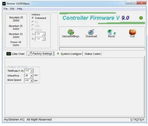
- Open «StromerV140404.exe»IMPORTANT!If the Stromer is connected correctly to the PC, the firmware version will be shown in the top right-hand corner of the screen and the status dot will be green. If the Stromer is not connected correctly to the PC, the version number will not be displayed. The status dot will be red. In this case, the wrong COM port may have been selected (tab: System Configure). The number of the firmware version is displayed in color; however, the different colors are only significant from Version 7.6 upward:Blue: Stromer is working properly.Red: After re-loading the firmware with XC800_FLOAD.exe: the settings still have to be loaded
- «Load Settings»«Select the command button for the right motor:
Mountain 25: Mountain25 250W Mountain 25: Mountain 25 500W Mountain 33: Mountain 33 500W Power 48: Power 48 500W - «Download»
- «Upload Settings», to check that the programming is correct (optional)
- «Quit»
 IMPORTANT!If the Stromer is connected correctly to the PC, the firmware version will be shown in the top right-hand corner of the screen and the status dot will be green. If the Stromer is not connected correctly to the PC, the version number will not be displayed. The status dot will be red. In this case, the wrong COM port may have been selected (tab: System Configure). The number of the firmware version is displayed in color; however, the different colors are only significant from Version 7.6 upward:
WIRING ST1
PROGRAMMING THE ASI CONTROLLER MY 2017 / ST1, AS OF 2017
IMPORTANT:PLEASE OBSERVE THE FOLLOWING POINTS TO ENSURE THAT NO DEFECTS ARISE DURING PROGRAMMING:
- Only use programming cable and programming switches (Figs 1 & 2) from Stromer. The programming plug required for all older models (511 software) is not used.
- The «XC Flood» and «Stromer 5T1» software applications must not be used (see ST1 programming instructions in Techbookl
DOWNLOADING AND INSTALLING THE SOFTWAREThe software can be downloaded from the Strainer Portal on the «Downloads» page in the ST1 area. After downloading, unzip the ZIP file and install the program.The programming cable may only be connected to the PC after the installation is complete!Switzerland=SetupST1MY17CHEU= SetupST1MY17EUUSA=SetupST1MY17USUnlike the previous ST1 motors, the ASI controller does not have a programming plug, and an A is referenced in the serial number (e.g. S1&-09A0117). When the Stromer is switched on, software version “04.9,> briefly appears on my display.1. START PROGRAM AND SELECT CORRECT COM PORTAfter the installation is complete, a shortcut to the program is placed on the desktop. Start the program by double-clicking this icon:
- Now insert the programming cable into a USB port on the PC and connect it to the motor cable of the Stromer: alternatively, it can also be connected to the display cable (see illustration)
- First, move the programming switch to the «OFF» position (0)
- Now move the programming switch to the ON position (I)
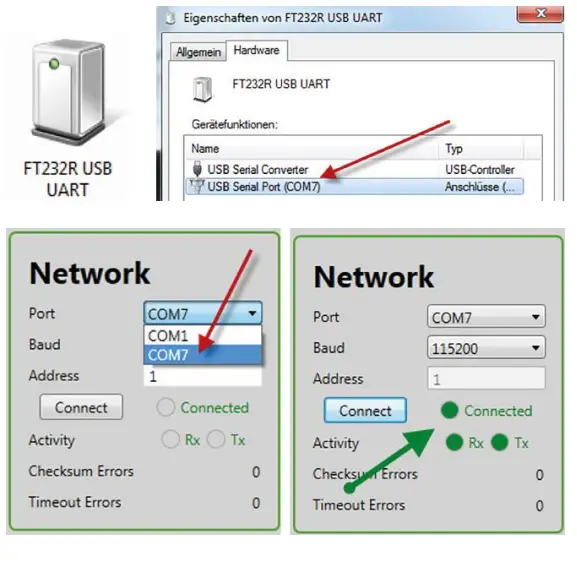
- Locate the correct COM port; you will find the programming cable in the «Devices and Printers» window on the Windows operating system 4 FT232R USB UART 4 Right-click on 4 Properties. Select the hardware and you will see the COM port 7)
- Close the Properties window (press OK) and dose the «Devices and Printers» window.
- Call up Stromer MY17 again, select the correct COM port in the upper right corner of the program and click Connects twice. The LEDs flash green when the connection has been successfully established.
2. PROGRAM MOTORSelect «Load from File* in the upper left corner under «parameter*.The folder containing the parameters is typically located at the following installation path: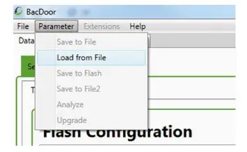 C:\Program Files (x863\ ST1 MY2017 ParameterSetsParameter sets: CH/EU.%USCH:Mountain 25=HUF5-A-500-25 Mountain 33=HUF5-A-500-37Power 48 =HUF6-A-500-45EU:Mountain 25=HUF5-A-250-25Mountain 33=HUF5-A-500-37Power 48=HUF6-A-500-45US:Class 1 M32=HUFS-A-500-32Class 3 P48=HUM-A-50045
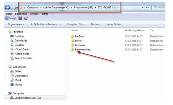 Select the correct file; only those that apply to the respective market (CH, EU, or US) are listedSelect the file for the motor fitted to the Stromer (e.g. Power48 = HUF6-8-500-45) and open; the application then starts.The «Parameters Saved to Flash* message appears at the 99% mark. Click «OK* to close.
 The «Parameters Saved to Flash* message appears at the 99% mark. Click «OK* to close.
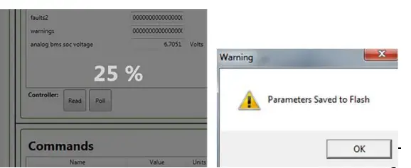
INSTALL SOFTWARE
Go to «File» and select «Bootloader».
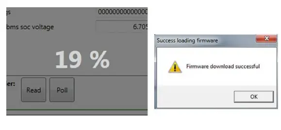
The folder is typically located at the designated installation path:C:\Program Files (x86)\ST1 MY2017 CH\FirmwareSelect the EHX file and choose «OK»; the installation routine then starts.
«Firmware download successful» is subsequently displayed.Choose «OK» to close; the firmware has been installed.
READOUT TMM VALUES AND OTHER INFORMATION
The values of the torque sensor can be read out on the «Informational» screen:
Throttle=TMMAxle torque sensor offset voltage=OFFSET
On the right side, several other values are listed such as:
- Software revision
- Battery voltage
- Battery state of charge
- Controller temperature
 report this ad
![]()
[xyz-ips snippet=”download-snippet”]