Model 381 On-Air BeltpackUser GuideIssue 4, March 2021This User Guide is applicable for serial numbersM381-00151 and later with application firmware 2.1 and later
Copyright © 2021 by Studio Technologies, Inc., all rights reserved studio-tech.com
Revision History
Issue 4, March 2021:• Improvements to formatting and terminology.Issue 3, February 2021:• Documents revisions and additions to talkback button modes.Issue 2, March 2020:• Revised nomenclature associated with the operation of talkback button.Issue 1, January 2019:• Initial release.
Introduction
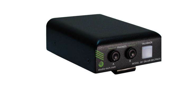
The Model 381 On-Air Beltpack offers a unique combination of audio resources to directly support a complete broadcast “stand-up” on-air position. Using Dante® audio-over-Ethernet technology, the unit provides main and talkback output channels, talent cue (IFB) input, and sidetone capabilities, as well as essential user controls in a compact, portable package. The Model 381 is compatible with the Dante Domain Manager™ (DDM) software application and is AES67-compliant for direct integration into many contemporary networked audio applications.Optimized for broadcast sports and live entertainment events, eSports, news-gathering, and streaming broadcast applications, the Model 381 allows incredibly simple deployment while maintaining “pro” audio quality and an intuitive user experience. With just a Power-over-Ethernet (PoE) connection, a dynamic or phantom-powered microphone, and a pair of headphones or an earpiece, the unit will be ready for “on-air” deployment. The controller software application is used for configuring operating parameters including microphone preamplifier gain, P48 phantom power, headphone signal routing, sidetone operation, and talkback button action. The Model 381’s audio quality is excellent, with low distortion, low noise, and high headroom. Careful circuit design and rugged components ensure long, reliable operation.
Applications
The Model 381 provides an “all-Dante” solution for one on-air talent location. Two Dante audio input channels supply the user with their talent cue (IFB) signals. Should the cue signal be “mix-minus” an integrated sidetone function can provide the user with a microphone confidence signal. Two Dante audio output channels, one designated as main (for “on-air” use) and the other talkback, are routed via the associated local-area network (LAN) to inputs on Dante-compatible devices. A pushbutton switch, located on the Model 381’s top panel, provides a combination talkback and “cough” function. Five configuration choices allow the exact action of the talkback button and associated function to be selected. Choices include whether or not the Dante main output channel is muted when talkback is active as well as offering the ability to disable the button. The audio switching is performed in the digital domain and is virtually “click-free.”
Setup and Operation
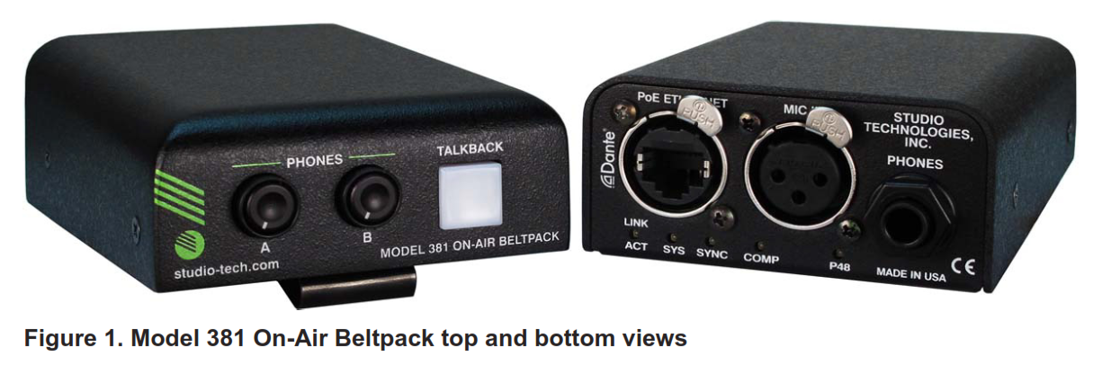
Set up and operation of Model 381 is simple. An etherCON® RJ45 jack is used to interconnect with a standard twisted-pair Ethernet port associated with a PoE-enabled network switch. This connection provides both power and bidirectional digital audio. A broadcast headset or handheld (“stick”) microphone can be directly connected to the unit’s 3-pin XLR microphone input connector. This input is compatible with dynamic or condenser microphones. An integrated P48 phantom power source can be enabled if desired. Stereo headphones, the headphone connections from a stereo or monaural headset, or even a monaural earpiece are connected to the headphone output jack. Two “push-in/push-out” rotary controls (potentiometers or “pots”) make it easy to set the level of the talent cue signals level being sent to the 2-channel headphone output. The ST controller software application is used to configure the wide range of Model 381 operating parameters. This allows the unit’s performance to be optimized to meet the needs of specific applications. The Model 381’s ultra-compact enclosure is made from an aluminum alloy that offers both lightweight and ruggedness. A stainless steel “belt clip,” located on the back of the unit, allows direct attachment to a user’s clothing. The top surface is curved to minimize the chance of the unit interfering with clothing or being readily observable “on camera.”
Ethernet Data and PoE
The Model 381 connects to a local area network (LAN) by way of a standard 100 Mb/s twisted-pair Ethernet interface. The physical 100BASE-TX interconnection is made by way of a Neutrik® etherCON RJ45 connector. While compatible with standard RJ45 plugs, etherCON allows a ruggedized and locking interconnection for harsh or high-reliability environments. The Model 381’s operating power is provided by way of the Ethernet interface using the 802.3af Power-over-Ethernet (PoE) standard. This allows fast and efficient interconnection with the associated data network. To support PoE power management, the Model 381’s PoE interface enumerates (reports) to the power sourcing equipment (PSE) that it’s a class 2 (low power) device.
Dante Audio-over-Ethernet
Audio data is sent to and received from the Model 381 using the Dante audio-over ethernet media networking technology. The Model 381’s two Dante transmitter (output) and two Dante receiver (input) audio channels can be assigned to other devices (routed) using the Dante Controller software application. The Dante transmitter (output) and receiver (input) channels are limited to supporting four Dante flows, two in each direction. The digital audio’s bit depth is up to 24 with a sampling rate of 44.1, 48, 88.2, or 96 kHz. Two bi-color LEDs provide an indication of the Dante connection status. The Model 381 is compatible with the AES67 interoperability standard. In this mode the two transmitters (output) channels will function in multicast; unicast is not supported. In addition, the unit is compatible with the Dante Domain Manager (DDM) software application.
Audio Quality
The Model 381’s performance is complete “pro,” making it appropriate for use in a wide range of applications. A low-noise, wide dynamic-range microphone preamplifier, and associated voltage-controlled-amplifier (VCA) dynamics controller (“compressor”) circuit ensures that mic input audio quality is preserved while minimizing the chance of signal overload. A configuration choice allows the selection of the signal source for the Dante main output channel. The choices are either the output of the microphone preamp or the output of the compressor circuit. These choices are referred to as “pre-compressor” or “post-compressor.” The ADC section utilizes a high-performance integrated circuit that supports sampling rates of 44.1, 48, 88.2, and 96 kHz with a bit depth of up to 24. The audio signal, now in the digital domain, routes through a 32-bit microprocessor and onto the Dante interface section where it is packetized and prepared for transport over Ethernet.
Audio input signals arrive via the Dante receiver (input) channels and pass into Model 381’s microprocessor. As with the Dante audio output channels, the sampling rate can be 44.1, 48, 88.2, or 96 kHz with a bit depth of up to 24. Channel routing, headphone level control, and sidetone creation are performed in the digital domain. This provides flexibility, allows precise control, and keeps the two controls from having to directly handle analog audio signals. The audio channels destined for the headphone output channels are sent to a high-performance digital-to-analog converter and then on to robust driver circuitry. High signal levels can be provided to a variety of headsets, headphones, and earpieces.
Configuration Flexibility
Model 381 can be configured to meet the needs of specific applications and user preferences. All configuration tasks are performed using the ST controller personal computer software application which is available free of charge on the Studio Technologies website. There are no mechanical switch settings or button-press sequences required to configure how the unit functions. Selectable parameters include microphone preamplifier gain, P48 phantom power on/off, headphone output performance, sidetone operation, talkback button operation, and main output audio source.
The gain of the microphone preamplifier can be selected from among five choices. This allows the Model 381 to match the output sensitivity of a range of handheld and headset-associated microphones. A low-noise source of P48 phantom power can be enabled if required to support condenser (capacitor) microphones. The two Dante receiver (input) audio sources and the way in which they are assigned to the headphone output channels can be configured. In addition, the operation of the two rotary controls can be selected. These unique choices allow almost any required headphone monitoring situation to be implemented. Whether for use in on-air sports, in an eSports broadcast, or as a production support tool, the Model 381 should be able to achieve the desired configuration.
The integrated sidetone function can be configured to operate from among three choices. This allows audio associated with the output of the microphone preamplifier to be returned to the headphone output as required. Sidetone can be important as some applications may provide a “mix- minus” talent cue signal that doesn’t include the user’s own voice content. A configuration selection allows the talkback button and associated function to be selected from among five choices, including having the ability to be disabled. The Dante main output channel can be selected to have its audio source be pre (before) or post (after) the dynamics control circuitry.
Future Capabilities and Firmware Updating
The Model 381 was designed so that its capabilities and performance can be enhanced in the future. A USB connector, located on the unit’s main circuit board (underneath the unit’s cover), allows the application firmware (embedded software) to be updated using a USB flash drive.
Model 381 uses Audinate’s Ultimo™ integrated circuit to implement the Dante interface. The firmware in this integrated circuit can be updated via the Ethernet connection, helping to ensure that its capabilities remain up to date.
Getting Started
What’s Included
Included in the shipping carton will be a Model 381 On-Air Beltpack and instructions on how to obtain an electronic copy of this guide. As a device that is Power-over-Ethernet (PoE) powered, no external power source is provided.
Connections
In this section signal, interconnections will be made using the three connectors located on the bottom of Model 381’s enclosure. An Ethernet data connection with Power-over-Ethernet (PoE) capability will be made using either a standard RJ45 patch cable or an etherCON protected RJ45 plug. A microphone will be connected using a cable-mounted 3-pin male XLR connector. A set of headphones or an earpiece will be connected by way of a 2- or 3-conductor ¼-inch plug. Ethernet Connection with PoE A 100BASE-TX Ethernet connection that supports Power-over-Ethernet (PoE) is required for Model 381 operation. This one connection will provide both the Ethernet data interface and power for the Model 381’s circuitry. A 10BASE-T connection is not sufficient as Dante does not support this Ethernet protocol. And a 1000BASE-T (GigE) connection is not supported unless it can automatically “fall back” to 100BASE-TX operation. The Model 381 supports Ethernet switch power management, enumerating itself as a PoE class 2 device.The Ethernet connection is made by way of a Neutrik etherCON protected RJ45 connector that is located on the bottom of the Model 381’s enclosure. This allows connection by way of a cable-mounted etherCON connector or a standard RJ45 plug. The Model 381’s Ethernet interface supports auto MDI/MDI-X so that a “cross-over” or “reversing” cable will never be required.
Microphone InputThe Model 381 provides a 3-pin female XLR connector which allows a balanced dynamic or phantom-powered condenser microphone to be connected. The microphone can be a standalone handheld (“stick”) type or can be part of a broadcast-style headset. The Model 381’s microphone input is directly compatible with balanced dynamic or P48 phantom-powered microphones. A microphone should be connected such that its common is on connector pin 1, its signal high (+) is on connector pin 2, and its sign low (–) is on connector pin 3. A controller configuration setting allows the P48 microphone power sources to be enabled or disabled as desired. Details on configuring the unit will be described later in this guide.Headphone OutputThe Model 381 provides a 2-channel (“stereo”) headphone output by way of a 3-conductor ¼-inch phone jack. Devices such as stereo headphones or “dual-ear” broadcast-style headsets can be directly connected using a 3-conductor ¼-inch plug. Following the usual convention the left channel should be terminated on the tip lead, the right channel on the ring leader, and common on the sleeve lead. It’s also possible to use a monaural (“single”) headset or broadcast-type single earbud as long as sufficient care is taken. If a 3-conductor ¼-inch plug is used by the device it should be wired such that the tip lead is connected to the positive terminal of the transducer and the sleeve lead is connected to the negative or common lead of the transducer; the plug’s ring should be left unconnected. But it’s also likely that the monaural device will be terminated on a 2-conductor (tip and sleeve) ¼-inch plug. When a plug of this type is inserted into the Model 381’s headphone output connector (jack) the Model 381’s right headphone output channel will be shorted. (This will occur since the ring lead will be directly shorted to the sleeve lead.) This can lead to stress on the Model 381’s right channel headphone output circuitry as well as drawing extra current from the output stage. To prevent this condition the Headphone Output – Controls (A/B) mode configuration choice should be set for Single-Channel Mono. This disables the right headphone output channel and sends the listen to an audio source or sources only to the left headphone output channel. Refer to a later section in this guide for details on configuring the headphone output.
Dante Configuration
For audio to pass to and from Model 381 requires the configuration of several Dante-related parameters. These configuration settings will be stored in non-volatile memory within Model 381’s circuitry.
The configuration will typically be done with the Dante Controller software application which is available for download free of charge at audinate.com. Versions of Dante Controller are available to support Windows and OS X® operating systems. Model 381 uses the Ultimo 2-input/2-output integrated circuit to implement the Dante architecture. The two Dante transmitter (output) channels associated with Model 381’s Dante interface must be assigned to the desired receiver (input) channels. This achieves routing the Model 381’s two output audio channels to the device (or devices) that will be “listening” to them. Within Dante Controller a “subscription” is the term used for routing a transmitter flow (a group of up to four output channels) to a receiver flow (a group of input channels). The number of transmitter flows associated with an Ultimo integrated circuit is limited to two. These can either be unicast, multicast, or a combination of the two. If the Model 381’s Dante transmitter (output) channels need to be subscribed (routed) to more than two flows it’s possible that an intermediary device, such as the Studio Technologies’ Model 5422A Dante Intercom Audio Engine, can be used to “repeat” the signals. The two Dante receiver (input) channels associated with Model 381’s audio inputs also need to be subscribed (routed) with the desired Dante transmitter (output) channels. These two audio signals will provide a Model 381 user with their headphone cue signals. Model 381 has a default Dante device name of ST-M381- and a unique suffix. The suffix identifies the specific Model 381 that is being configured. The suffix’s actual alpha and/or numeric characters relate to the MAC address of the unit’s Ultimo integrated circuit. The two Dante transmitter (output) channels have default names of Main and Talkback. The two Dante receiver (input) channels have default names of Headphone Ch1 and Headphone Ch2. Using Dante Controller, the default device name and channel names can be revised as appropriate for the specific application. The Model 381 supports audio sample rates of 44.1, 48, 88.2, and 96 kHz. A setting in Dante Controller is used to configure the desired sample rate. The Model 381 can serve as the Leader clock for a Dante network but in most cases, it will be configured to “sync” to another device. No clock configuration settings associated with Model 381 will typically require configuration within Dante Controller.
Model 381 Configuration
The ST controller software application is used to configure the way in which the Model 381 functions. No DIP switch settings or other local actions are used to configure the unit. This makes it imperative that STcontroller be available for convenient use in a personal computer that’s connected to the related LAN.
Installing ST controller
ST controller is available free of charge on the Studio Technologies website (studio-tech.com/stcontroller). If required, download and install ST controller onto a designated personal computer. This personal computer must be on the same local area network (LAN) and subnet as the Model 381 unit or units that are to be configured. Immediately after starting ST controller, the application will locate the devices that it can control. The Model 381 unit or units will appear in the device list. Use the Identify command to allow easy recognition of a specific Model 381 unit. Double-clicking on a device name will cause the associated configuration menu to appear. Review the current configurationand make changes as required.ParametersThe configurable functions include:• P48 phantom power on/off status• Microphone preamplifier gain• Headphone output routing and level control operation• Sidetone operation and level• Talkback button operation• Main output audio sourceChanges made using ST controller will be immediately reflected in the unit’s operation. No “reboot” of Model 381 is required. Each time a change is made the talkback button on the top panel will flash orange in two quick sequences to indicate that command from ST controller has been received.
Microphone Input – P48 Phantom Power
ST controller allows selection of the on/off status of the microphone input’s P48 phantom power source. The on/off status is displayed by way of an LED, red in color, located on the bottom panel adjacent to the microphone input connector. Select the status of the P48 source to meet the needs of the connected microphone.
Microphone Input – GainChoices are 36 dB, 42 dB, 48 dB, 54 dB, and 60 dB. The gain of the Model 381’s microphone the preamplifier can be selected from among five choices. The compressor active LED, orange in color and visible on the bottom of the Model 381’s enclosure adjacent to the microphone input connector, can act as a guide when setting the preamp gain. When a voice signal at a normal level is present on the microphone input the compressor active LED should light intermittently. If, for example, it rarely lights and the gain is set to 42 dB, it might be a good idea to change the setting to 48 dB. If the LED is lit fully while speaking at a normal level into the microphone and the gain is set for 54 dB or 60 dB, changing the gain to one of the lower values might be warranted. There’s no “hard and fast” rule about which gain setting is appropriate. But unless otherwise indicated, 42 dB is typically a good initial choice.
Headphone Output – RoutingChoices are Dual-Channel Stereo, DualChannel Mono, and Single-Channel Mono. ST controller allows selection from among three headphone output modes. Each mode is distinct and careful selection will help optimize Model 381’s operation for a range of applications.Dual-Channel StereoThe Dual-Channel Stereo mode is provided for on-air applications where two independent audio sources need to be routed to the two headphone output channels. Dante audio input channel 1 will be routed to the left headphone output channel and Dante audio input channel 2 will be routed to the right headphone output channel. Note that in this mode the sidetone audio signal will be routed to both the left and right headphone output channels.Dual-Channel MonoThe Dual-Channel Mono mode can be useful in applications where the same audio signals need to be provided to the user on both the left and right headphone output channels. In this mode, Dante audio inputs 1 and 2 are combined (mixed together or “summed”) and routed to both the left and right headphone output channels. Note that in this mode the sidetone audio signal will be routed to both the left and right headphone output channels.Single-Channel MonoThe Single-Channel Mono mode is specifically provided for applications where a 2-conductor ¼-inch plug is being used with the connected headphones, headset, or a broadcast-style earpiece. In this mode Dante audio inputs 1 and 2 are combined to monaural and routed to only the left channel of the headphone output; no audio signal is routed to the right channel of the headphone output. Note that in this mode the sidetone audio signal will be routed to only the left headphone output channel.
Headphone Output – Controls (A/B)Choices are Ch 1 Level / Ch 2 Level, Ch 1 & 2 Level / Balance, and Ch 1 & 2 Level / Sidetone Level. Three configuration choices in ST controller allow the selection of the manner in which the two rotary controls (“pots”), labeled A and B, will function.
Ch 1 Level / Ch 2 LevelThis mode is provided for on-air applications where independent control of the channel 1 and channel 2 input signals is required. The control on the left, labeled A, will allow adjustment of input channel 1. The control on the right, labeled B, will allow adjustment of input channel 2. Note that in this mode the level of the sidetone audio signal will be determined by the configuration of the Fixed Sidetone Level setting.Ch 1 & 2 Level / BalanceThis mode is provided primarily for use in “stereo” applications such as live music events or radio broadcasts. In these applications, it’s typical to want the user to have single control to simultaneously adjust the level of both input channels 1 and 2 with a separate control used to adjust the left/right level balance. When the Headphone Output – Routing configuration is set for Dual-Channel Stereo the control on the left, labeled A, will be used to adjust the level of both input channels 1 and 2. The control on the right, labeled B, will be used to adjust the balance of the channel levels. If the Headphone Output – Routing configuration is set to either of the mono choices the action of the balance control, on the right and labeled B, will simply change the level ratio of input 1 versus input 2. Also, note that in this mode the level of the sidetone audio signal will be determined by the configuration of the Fixed Sidetone Level setting.
Ch 1 & 2 Level / Sidetone LevelThis mode is provided for applications where the user needs to adjust the level of both the audio input channels and the sidetone signal as they are sent to the headphone output channel or channels. The control on the left, labeled A, will be used to adjust the level of both input channels 1 and 2. The control on the right, labeled B, will be used to adjust the level of the sidetone signal. Note that in this mode the configuration choice for Fixed Sidetone Level will be “grayed out” (become inactive) as it will not be utilized.
Headphone Output – Sidetone ModeChoices are Main Active, Talkback Active, and Always Active. The overall model of Model 381’s side-tone function can be configured. Sidetone is audio from the microphone input that is sent to the headphone output channel or channels. This can be important, allowing the user to “hear” themselves for performance confirmation and comfort. Making a specific selection from among the three available modes will depend on the needs of the application. If a “full mix” is being provided to the Model 381’s audio inputs then locally provided sidetone won’t e needed when “on-air,” i.e., the main output is enabled. The user will hear themselves by way of the audio signals being routed to the Dante audio input channels. But if a “mix-minus” is being supplied to the Model 381 then having one of the sidetone modes enabled can be an important means of establishing user confidence. There are also cases where a “full mix” is provided but the user desires to hear themselves when the talkback function is active. Note that the actual level of sidetone audio as it is sent the headphone output will be determined by the configuration of the Headphone Output – Controls (A/B) selection. It will either follow the Fixed Sidetone Level configuration or the position of the level control that is located on the right and labeled B. STcontroller allows selection from among three sidetone modes:
Main ActiveIn this mode the sidetone function will be active whenever the main output is active, i.e., the audio signal associated with the microphone input is present on the Dante main output channel.Talkback ActiveIn this mode, the sidetone function will be active whenever the talkback function is active and the audio signal is present on the Dante talkback output channel.Always ActiveIn this mode, the sidetone function will always be active and sidetone audio will be continuously routed to the headphone output.
Headphone Output – Fixed Sidetone LevelChoices are Off Low, Medium Low, Medium, Medium High, and High. When the configuration for the Headphone Output – Controls (A/B) is set for either of the dual-channel modes the level of the sidetone audio will follow the Fixed Sidetone Level setting. This level can be selected from among five values. The correct value is simply the one that makes the user most comfortable. Sidetone audio can also be disabled by selecting the Off choice. Selecting Off is useful for applications such as when user microphone audio (a “full mix”) is being returned as part of their listening to audio signals. As previously discussed, the Fixed Sidetone Level choice will be “grayed out” and inaccessible if the Ch 1 & 2 / Sidetone mode is selected for the Headphone Output –Controls (A/B) configuration choice. In this case, the rotary control on the right, labeled B, will be used to adjust the sidetone level.
Talkback Button – OperationChoices are Momentary – Mutes Main Out, Latching – Mutes Main Out, Momentary – Doesn’t Mute Main Out, Latching – Doesn’t Mute Main Out, and Disabled. ST controller allows the operating configuration of the talkback button to be selected. There are five choices available.Momentary – Mutes Main OutIf this mode is selected when the talkback button is not pressed the microphone signal will be sent to the Dante main output channel and the Dante talkback output channel will be muted. The green LED associated with the talkback button will be lit. Whenever the talkback button is pressed and held the audio signal will mute on the Dante main output channel and the audio signal will become active on the Dante talkback output channel. In addition, the talkback button’s LED will light orange.Latching – Mutes Main OutIf this mode is selected the talkback function will alternate between its off (inactive) and on (active) states whenever the talkback button is momentarily pressed. The button’s LED will light green whenever the Dante main output is active and light orange whenever the Dante talkback output is active. Upon power being initially applied to Model 381 the talkback function will be inactive, audio will be present on the Dante main output, and the talkback button’s LED will be lit green.
Momentary – Doesn’t Mute Main OutIf this mode is selected when the talkback button is not pressed the microphone signal will be sent to the Dante main output channel and the Dante talkback output channel will be muted. The green LED associated with the talkback button will be lit. Whenever the talkback button is pressed and held the audio signal will continue to be present on the Dante main output channel while the audio signal will also become active on the Dante talkback output channel. In addition, the talkback button’s LED will alternate be- tween lighting green and lighting orange to indicate that both Dante transmitter (output) channels are active.
Latching – Doesn’t Mute Main OutIf this mode is selected the talkback function will alternate between its off (inactive) and on (active) states whenever the button is momentarily pressed. In either state audio will be sent out the Dante main output channel; it will never mute. The talkback button’s LED will light green whenever the Dante main output is active and the Dante talkback output is not active. It will alternate between lighting green and lighting orange whenever the talkback function is active. This indicates that audio is being sent to both the Dante main output channel and the Dante talkback audio output channel. Upon power being initially applied to Model 381 the talkback function will not be active and no audio will be sent to the Dante talkback output channel. Audio will be sent to the Dante main output channel and the talkback button’s LED will be lit green.DisabledIf this mode is selected the talkback function is prevented from becoming active. Microphone audio will always be sent to the Dante main output channel; the Dante talkback output channel will be muted. The talkback button’s LED will light green. Whenever the talkback button has pressed no change to the audio routing will take place; audio will always be present on the Dante main output channel. Also, whenever the talkback button is pressed button’s green LED will flash as an alert, indicating to users that the talkback function has been disabled.
System Mode – Main Output SourceChoices are Pre-Compressor and PostCompressor. This ST controller selection allows the audio source for the main output channel to be selected. There are two choices available. In most cases, the post-compressor selection will be appropriate. In all cases, the output of the compressor circuitry will be used by the talkback output (transmitter) channel.Pre-CompressorWhen selected for Pre-Compressor the audio source for the Dante main output channel will be the output of the microphone preamplifier. No dynamic range control is performed on the signal that is provided to the main output. This selection can be appropriate when the most accurate representation of the microphone input signal is desired. This would allow maximum “downstream” control of a signal that is to be used for “on-air” or other primary purposes. Any processing of audio coming from the main output channel would need to be performed in equipment that’s “post” (after) the Model 381 in the audio chain. The downside of selecting a pre-compressor is an increased risk of signal overload.
Post-CompressorWhen selected for Post-Compressor the audio source for the Dante main output channel will be the output of the dynamics control (compressor) circuitry. This can help prevent excessive signal levels from being sent out the main output channel and on to the next audio device in the signal “chain.” With a threshold of just above the nominal digital output level and a “gentle” compression ratio of just 2 to 1, in most cases the impact of the compressor on voice audio signals will be minimal while helping to prevent audio overloads.
Operation
At this point, everything should be ready such that the Model 381 operation can commence. An Ethernet connection with Power over-Ethernet (PoE) capability should have been made. A microphone and headphones or an earbud should have been connected. Alternately, a broadcast-tyle headset may be utilized. The Model 381’s Dante configuration settings should have been selected using the Dante Controller software application. In this way, the unit’s two Dante transmitter (output) channels and two Dante receiver (input) channels should have been routed (subscribed) to the Dante receiver (input) and Dante transmitter (output) channels on associated equipment. The Model 381’s operating configuration should have been established using the ST controller application. This will ensure that the unit will meet the needs of the specific application.Initial OperationThe Model 381 will start to function as soon as a Power-over-Ethernet (PoE) power source is connected. However, it may take 20 to 30 seconds for full operation to commence. Upon initial power, up the three status LEDs located on the bottom panel, below the etherCON RJ45 jack, will begin to light as the network and Dante connections are established. The COMP LED, adjacent to the microphone input connector, may or may not flash momentarily. The P48 LED, also located adjacent to the microphone input connector, will flash once to indicate that it is functioning. The green and orange LED indicators within the talkback pushbutton switch will each light once to indicate that the main operating firmware (embedded software) has started functioning. Once the power-up sequence has completed and the Dante connection has been established full operation will begin. The unit’s various LEDs will become operational, displaying the sta- tus of their designated functions.
How to Identify a Specific Model 381Functions within the Dante Controller and ST controller software applications allow a specific Model 381 unit to be identified. Each application provides an “eyeball” icon that when selected (“clicked”) will activate the Identify function. When Identify is selected it will send a command to the designated Model 381 unit. On that unit the orange LED associated with the talkback pushbutton switch will flash on and off approximately eight times. (Of course, the Identify command will not change the on/off status of the button.) In addition, the SYS and SYNC status LEDs, located directly below the etherCON RJ45 connector on the bottom panel, will slowly flash green. After a few seconds, this LED identification pattern will cease and normal Model 381 talkback button LED and Dante status LED operation will resume.
Ethernet and Dante Status LEDsAs previously mentioned, there are three status LEDs located below the etherCON RJ45 connector on Model 381’s bottom panel. The LINK ACT LED lights green whenever an active connection to a 100 Mb/s Ethernet network has been established. It will flash in response to Ethernet data packet activity. The SYS and SYNC LEDs display the operating status of the Dante interface and associated network. The SYS LED will light red upon Model 381 power up to indicate that the Dante interface is not ready. After a short interval, it will light green to indicate that it is ready to pass data with another Dante device. The SYNC LED will light red when the Model 381 is not synchronized with an ante network. It will light solid green when the Model 381 is synchronized with a Dante network and an external clock source (timing reference) is being received. It will slowly flash green when the Model 381 is part of a Dante network and it is serving as a Leader clock. It’s possible that up to 30 seconds may be required for the SYNC LED to reach its final state.
P48 Status LEDA red LED indicator is located on the bottom panel adjacent to the microphone input connector. It is labeled P48 and will light whenever the P48 phantom power source is active and providing power to the microphone input.
Compressor Active LED and Mic Preamp GainAn orange LED indicator is located on the bottom panel, also adjacent to the microphone input connector. It is labeled COMP and displays the status of the microphone audio compressor function. This function controls the dynamic range of the audio signal that is sent to the talkback output channel as well as being used by the side-tone function. This signal may also, depending on a configuration setting, be present on the Dante main output channel. The compressor LED will light whenever the input signal from the microphone, along with the configured mic preamp gain, is of sufficient level such that the dynamic range of the microphone signal is being actively controlled. It’s perfectly acceptable for this LED to light intermittently whenever a user is talking at a normal voice level into an associated microphone. But if the COMP LED lights solid orange while a user is talking at a normal voice level this will typically indicate that the mic gain should be reduced. Conversely, if the COMP LED almost never lights when normal talking is taking place, it’s likely that changing the gain to a higher value would be beneficial. Note that due to the design of the circuitry the compressor active LED will function whether or not the main, talkback, or sidetone functions are active.
Headphone Output – GeneralUsers should find the headphone output audio quality to be excellent, with a high maximum output level and low distortion. Two rotary controls (potentiometers or “pots”) are located on the top panel and are “push-in/push-out” types. This allows their associated knobs to be in the “out” position when the level needs to be adjusted and in the “in” position when protection from an unwanted change is desired. Analog audio signals do not pass directly through the two controls. The position of the controls is recognized by Model 381’s processor which then adjusts the actual signal level within the digital domain.
Headphone Output – Routing and Controls (A/B)How the two rotary controls function will depend on two configuration settings as made using the ST controller application. The Headphone Output – Routing mode configures how the two Dante audio inputs, Ch 1 and Ch 2, are assigned to the two headphone output channels. The Headphone Output – Controls (A/B) configuration determines exactly the way in which the two controls will function. Since the two configurations each offer three choices, this provides nine separate configurations that each provide a unique operating scenario.
When Headphone Output – Routing is configured to the Dual-Channel Stereo mode:• In the Ch 1 Level / Ch 2 Level mode the control on the left, labeled A, is used to adjust the level of the channel 1 input audio signal as it is being sent to the left channel of the headphone output. The control on the right, labeled B, is used to control the level of the channel 2 input audio signal as it is sent to the right headphone output. Sidetone audio, whose level will follow the Fixed Sidetone Level configuration, will be sent to both the left and right headphone output channels.• In the Ch 1 & 2 Level / Balance mode the control on the left, labeled A, adjusts the level of the Ch 1 input audio signal as it is being sent to the left headphone output and the Ch 2 input audio signal as it is being sent to the right headphone output. The control on the right, labeled B, will adjust the level balance of both audio in- put Ch 1 and audio input Ch 2 as they are sent to the headphone output channels. The level of the sidetone audio will follow the Fixed Sidetone Level configuration and will be sent to both the left and right headphone output channels.• In the Ch 1 & 2 Level / Sidetone Level mode the control on the left, labeled A, adjusts the level of both the Ch 1 input audio signal as it is being sent to the left headphone output and the Ch 2 input audio signal as it is being sent to the right headphone output. The control on the right, labeled B, adjusts the level of the sidetone audio as it is being sent to both the left and right channels of the headphone output. In this mode, the Fixed Sidetone Level configuration will be ignored.
When Headphone Output – Routing is configured to the Dual-Channel Mono mode:• In the Ch 1 Level / Ch 2 Level mode the control on the left, labeled A, is used to adjust the level of the channel 1 input audio signal as it is being sent to both the left and right headphone output channels. The control on the right, labeled B, controls the level of the channel 2 input audio signal as it is sent to both the left and right headphone output channels. Sidetone audio, whose level will follow the Fixed Sidetone Level configuration, will be sent to both the left and right headphone output channels.• In the Ch 1 & 2 Level / Balance mode the control on the left, labeled A, adjusts the level of both the Ch 1 and Ch 2 input audio signals as they are sent to both the left and right headphone output channels. The control on the right, labeled B, will adjust the level balance of audio input Ch 1 and audio input channel 2. The level of the sidetone audio will follow the Fixed Sidetone Level configuration and will be sent to both the left and right headphone output channels.• In the Ch 1 & 2 Level / Sidetone Level mode the control on the left, labeled A, adjusts the level of both the Ch 1 and Ch 2 input audio signals as they are sent to both the left and right headphone output channels. The control on the right, labeled B, adjusts the level of the sidetone audio as it is being sent to both the left and right channels of the headphone output. In this mode the Fixed Sidetone Level configuration will be ignored.
When Headphone Output – Routing is configured to the Single-Channel Mono mode:• In the Ch 1 Level / Ch 2 Level mode the control on the left, labeled A, is used to adjust the level of the channel 1 input audio signal as it is being sent to the left headphone output channel. The control on the right, labeled B, controls the level of the channel 2 input audio signal as it is sent to the left headphone output channel. Sidetone audio, whose level will follow the Fixed Sidetone Level configuration, will be sent to the left headphone output channel.• In the Ch 1 & 2 Level / Balance mode the control on the left, labeled A, adjusts the level of both the Ch 1 and Ch 2 input audio signals as they are sent to the left headphone output channel. The control on the right, labeled B, will adjust the level balance of audio input Ch 1 and audio input channel 2. The level of the sidetone audio will follow the Fixed Sidetone Level configuration and will be sent to the left headphone output channel.• In the Ch 1 & 2 Level / Sidetone Level mode the control on the left, labeled A, adjusts the level of both the Ch 1 and Ch 2 input audio signals as they are sent to the left headphone output channel. The control on the right, labeled B, adjusts the level of the sidetone audio as it is being sent to the left headphone output channel. In this mode, the Fixed Sidetone Level configuration will be ignored.
Sidetone Function ActivityThe Model 381’s sidetone function is used to send post-compressor microphone audio to the headphone output as a user confirmation signal. When sidetone audio will be actively sent to the headphone output will depend on the configuration of the Headphone Output – Sidetone Mode in the ST controller application. The Sidetone Mode can be configured such that sidetone audio will be active when the main output is active, is active when the talkback output is active or is active at all times. Whether sidetone audio will be sent to the left and right headphone output channels or only the left headphone output channel will depend on the configuration of the Headphone Output – Routing configuration in ST controller. As expected, when the Headphone Output – Routing mode is configured for Dual-Channel Stereo or Dual- Channel Mono sidetone audio will be sent to both the left and right headphone output channels. When configured for Single-Channel Mono sidetone audio will be sent only to the left headphone output channel. Depending on the configuration of the Headphone Output – Controls selection in ST controller, the level of the sidetone audio will be determined either by the selected value in the Fixed Sidetone Level configuration or by adjustment of the right control, labeled B, that is located on the top panel. Typically, providing a precise sidetone level is not important and most users will not be concerned about setting it to a specific value. But ensuring that the level of the sidetone audio is reasonable is important. Setting the level too low will encourage a user to speak too loudly; setting it too high and the user will be tempted to speak hesitantly.
Talkback ButtonThe manner in which the talkback pushbutton impacts Model 381’s operation depends on how the function has been configured in the ST controller. The specific actions that occur will depend on its configuration as selected from the five available choices.Momentary – Mutes Main OutWhen the Talkback Button – Operation selection has been configured for Momentary – Mutes Main Output its functionality will be pretty self-explanatory. When the talkback button is not pressed its LED is lit green and audio is sent out the Dante main output channel. Press and hold the button to enable the talkback function. When talkback is enabled the talkback button’s LED will light orange, microphone audio will be sent out to the Dante talkback output channel, and the Dante main output channel will be muted.
Latching – Mutes Main OutIf the talkback button has been configured for the Latching – Mutes Main Out mode it operates a bit differently. Momentarily pressing (“tapping”) the talkback button will cause the talkback function to change states: off-to-on or on-to-off. Whenever the talkback function in not enabled, microphone audio is sent only to the Dante main output channel and the talkback button’s LED will light green. The button’s LED will light orange when the talkback function is enabled and microphone audio is being sent out the Dante talkback output channel while the Dante main output channel is muted.
Momentary – Doesn’t Mute Main OutWhen the Talkback Button – Operation selection has been configured for Momentary– Doesn’t Mute Main Out microphone audio will always be present on the Dante main output channel. When the talkback button is being pressed its LED will be lit green and audio won’t be sent out the Dante talkback output channel. Pressing and holding the button will enable the talkback function. When talkback is enabled the talkback button’s LED will alternate between lighting green and lighting orange. This indicates that microphone audio is being sent out both the Dante main output channel and the Dante talkback output channel.Latching – Doesn’t Mute Main OutIf the talkback button has been configured for Latching – Doesn’t Mute Main Out microphone audio will always be present on the Dante main output channel. Momentarily pressing (“tapping”) the talkback button will cause the talkback function to change states: off-to-on or on-to-off. Whenever the talkback function is not active, the talkback button’s LED will light green to indicate that audio is present on the Dante main output channel. When the talkback function is active the talkback button’s LED will alternate between lighting green and lighting orange. This indicates that both audio output channels are enabled; microphone audio will be present on both the Dante main output channel and the Dante talkback output channel.DisabledWhen the talkback button function has been configured for Disabled no talkback action will take place. If the push button is pressed its associated LED will flash green as an indication that it is disabled. Audio will continue to be routed only to the Dante main output channel. No audio will be routed to the Dante talkback output channel.
Technical Notes
IP Address AssignmentBy default, Model 381’s Ethernet interface will attempt to automatically obtain an IP address and associated settings using DHCP (Dynamic Host Configuration Protocol). If a DHCP server is not detected an IP address will automatically be assigned using the link-local protocol. This protocol is known in the Microsoft® world as Automatic Private IP Addressing (APIPA). It is also sometimes referred to as auto-IP (PIPPA). Link-local will randomly assign a unique IP address in the IPv4 range of 169.254.0.1 to 169.254.255.254. In this way multiple Dante-enabled devices can be connected together and automatically function, whether or not a DHCP server is active on the LAN. Even two Dante-enabled devices that are directly interconnected using an RJ45 patch cord will, in most cases, correctly acquire IP addresses and be able to communicate with each other.An exception does arise when trying to directly interconnect two Dante-enabled devices that use Ultimo integrated circuits to implement Dante. The Model 381 uses the Ultimo “chip” and, as such, direct one to one interconnection to another Ultimobased product is not supported. An Ethernet switch linking the two units is required to successfully interconnect two Ultimo-based devices. The technical reason that a switch is required relates to the need for a slight latency (delay) in the data flow; an Ethernet switch will provide this.Using the Dante Controller software application, Model 381’s IP address and related network parameters can be set for a fixed (static) configuration. While this is a more involved process than simply letting DHCP or link-local “do their thing,” if fixed addressing is necessary then this capability is available. But in this case, it’s highly recommended that every unit be physically marked, e.g., directly using a permanent marker or “console tape,” with its specific static IP address. If knowledge of a Model 381’s IP address has been misplaced there is no reset button or other method to easily restore the unit to a default IP setting.In the unfortunate event that a device’s IP address is “lost,” the Address Resolution Protocol (ARP) networking command can be used to “probe” devices on a network for this information. For example, in Windows OS the arp –a command can be used to display a list of LAN information that includes MAC addresses and corresponding IP addresses. The simplest means of identifying an unknown IP address is to create a “mini” LAN with a small PoE-enabled Ethernet switch connecting a personal computer to the Model 381. Then by using the appropriate ARP command the required “clues” can be obtained.
Optimizing Network PerformanceFor best Dante audio-over-Ethernet performance a network that supports VoIP QoS capability is recommended. In applications that utilize multicast Ethernet traffic enabling IGMP snooping can be valuable. These protocols can be implemented on virtually all contemporary managed Ethernet switches. There are even specialized switches that are optimized for entertainment-associated applications. Refer to the Audinate website (audinate.com) for details on optimizing networks for Dante applications.
Application Firmware Version DisplayThere are two ways in which the version number of the Model 381’s application firmware (embedded software) can be identified. One requires only the Model 381 unit and involves a button press sequence performed upon power-up. The other method utilizes Model 381 and the ST controller software application. Either method may prove to be useful when working with factory personnel on application support and troubleshooting. As part of Model 381’s power-up sequence, the unit’s application firmware can be directly displayed. Before connecting the PoE-enabled Ethernet cable, press and hold the talkback button. Then connect the Ethernet cable. Upon application of PoE power, the Model 381 will not go through its normal power-up sequence but instead will display the firmware version. The LED associated with the talkback button will “flash” green in color to display the major version number and then “flash” orange to display the minor version number. Then the LED will remain off until the talkback button is released. Once the talkback button is released normal operation will then take place. As an example of what would be a typical firmware display, if the talkback button’s LED “flashes” green once followed by the LED “flashing” orange once it would indicate that application firmware version 1.1 is present in the Model 381. A selection in the ST controller software application allows Model 381’s application firmware version to be identified. Connect the Model 381 unit to the network and let it connect and start to function. Then, after starting ST controller, review the list of identified devices and select the specific Model 381 from which you want to determine its application firmware version. Then select Version under the Device tab. A page will then display that will provide lots of useful information. This includes the application firmware version and well as details on the Dante interface firmware.
Application Firmware Update ProcedureIt’s possible that updated versions of the application firmware (embedded software) that is utilized by the Model 381’s processor (microcontroller or MCU) integrated circuit will be released to add features or correct issues. Refer to the Studio Technologies website for the latest application firmware file. The unit has the ability to load a revised file into the MCU’s non-volatile memory by way of a USB interface. The Model 381 implements a USB host function that directly supports the connection of a USB flash drive. The Model 381’s MCU updates its firmware using a file named m381.bin. The update process begins by preparing a USB flash drive. The flash drive doesn’t have to be empty (blank) but must be in the personal-computer-standard FAT32 format. The processor in the Model 381 is compatible with both USB 2.0, USB 3.0, and USB 3.1-compliant Flash drives. Save the new firmware file in the root directory with the name m381.bin. Studio Technologies will supply the application firmware file inside a .zip archive file. While the firmware file inside of the zip file will adhere to the naming convention required by the Model 381, the name of the zip file itself will include the file’s version number. For example, a file named m381v1r2MCU.zip would indicate that version 1.2 of the application firmware (m381.bin) is contained within this zip file.Once the USB flash drive is inserted into the USB interface, located on the main circuit board under the cover, the unit must be powered off and again powered on. At this point, the file will automatically load. The precise steps required will be highlighted in the next paragraphs of this guide.
To install the application firmware file follow these steps:1. Disconnect power from Model 381. This will entail removing the Ethernet connection that is providing PoE power.2. Remove the cover from Model 381. Begin by removing the four Phillips head screws (#1 screwdriver tip), two per side. Be certain to save the screws so that re-assembly will be fast and painless. Then carefully slide the cover forward to separate it from the level controls and button and then lift it off.3. Locate the USB connector on the main circuit board. It’s near the top of the unit, directly between the two rotary level controls. Insert the prepared USB flash drive into it.4. Apply power to Model 381 by connecting to a Power-over-Ethernet (PoE) Ethernet source.5. After a few seconds the Model 381 will run a “boot loader” program that will automatically load the new application firmware file (m381.bin). This loading process will take only a few seconds. During this time period, the talkback button LED will flash slowly in alternate colors. Once the entire loading process is over, taking approximately 10 seconds, the Model 381 will restart using the newly-loaded application firmware.6. At this time the Model 381 is functioning with the newly-loaded application firmware and the USB flash drive can be removed. But to be conservative, remove PoE power first and then remove the USB flash drive.7. Confirm that the desired firmware version has been correctly loaded. This can be done by pressing and holding the talkback button, applying power to the Model 381, and then “reading” the application firmware version number by observing the talkback button’s LED. Alternately, the ST controller application can be used to identify the application firmware version number. Whatever method you use, ensure that the desired version is present.Note that upon power being applied to Model 381 if a connected USB flash drive doesn’t have the correct file (m381.bin) in the root folder no harm will occur. Upon power-up, the talkback button’s LED will flash on and off rapidly for a few seconds to indicate this condition and then normal operation using the unit’s existing application firmware will begin.
Ultimo Firmware UpdateAs previously discussed in this guide, Model 381 implements Dante connectivity using the 2-input/2-output Ultimo integrated circuit from Audinate. The Dante Controller software application can be used to determine the version of the firmware (embedded software) residing in the Ultimo “chip.” This firmware can be updated by way of Model 381’s Ethernet connection. The latest Dante firmware file is available on the Studio Technologies website. The Dante Firmware Update Manager (FUM) application is used to install the firmware. This program is also available for download on the Studio Technologies website. It’s anticipated that a more automated method of updating Dante firmware will become available by way of a new version of Dante Controller. If this comes to fruition then it might offer a much-simplified method of keeping the firmware current.Restoring Factory DefaultsA command in the ST controller software application allows the Model 381’s defaults to be reset to the factory values. From ST controller select Model 381 for which you want to restore its defaults. Select the Device tab and then the Defaults tab. Select the Factory Defaults feature. Then click on the OK box. Refer to Appendix A for a list of Model 381’s factory defaults.
Specifications
Power Source:Power-over-Ethernet (PoE): class 2 (low power,≤6.49 watts) per IEEE® 802.3afNetwork Audio Technology:Type: Dante audio-over-EthernetAES67-2018 Support: yesDante Domain Manager (DDM) Support: yesBit Depth: up to 24Sample Rate: 44.1,48, 88.2, and 96 kHzNumber of Transmitter (Output) Channels: 2Description of Transmitter Channels: main(pre-or post-compressor, selectable), talkback (post-compressor)Number of Receiver (Input) Channels: 2Description of Receiver Channels: headphonechannel 1 and headphone channel 2Dante Audio Flows: 4; 2 transmitter, 2 receiverNetwork Interface:Type: 100BASE-TX, twisted-pair Ethernet, Powerover-Ethernet (PoE) supportedData ate: 100 Mb/s (10 Mb/s and 10000 Mb/s “GigE” Ethernet not supported)Microphone Input:Compatibility: dynamic or phantom-powered microphonesType: balanced, capacitive coupledImpedance: 2.8 k ohms, nominalGain: 36, 42, 48, 54, and 60 dB, selectableFrequency Response: 30 Hz to 20 kHz, –3 dB at 30 Hz, –0.6 dB at 20 kHzDistortion (THD+N): <0.020%, 1 kHz, 36 dB gain, –32 dBu input levelDynamic Range: 96 dB, A-weightedPhantom Power: P48 per IEC 61938 standard, on/off selectable with status LEDCompressor:Application: always used for Dante talkback audio output channel can be used for Dante main output channelThreshold: 1 dB above nominal level (–19 dBFS)Slope: 2:1Status LED: compressor activeHeadphone Output:Type: 2-channelCompatibility: intended for connection to stereo(dual-channel) or mono (single-channel) headphones, headsets or earpieces with nominal impedance of 50 ohms or greaterMaximum Output Voltage: 3.1 Vrms, 1 kHz, 150-ohm loadFrequency Response: 20 Hz to 20 kHz, +0/–1 dBDistortion (THD+N): 0.001%, +10 dBu output, 150-ohm loadDynamic Range: >102 dBConnectors:Microphone Input: 3-pin female XLRHeadphone Output: ¼-inch 3-conductor jackEthernet: Neutrik etherCON RJ45USB: type A receptacle (located inside Model 381’s enclosure and used only for updating the firmware)Configuration: uses Studio Technologies’ ST controller personal computer application Environmental:Operating Temperature: 0 to 50 degrees C (32 to 122 degrees F)Storage Temperature: –40 to 70 degrees C (–40 to 158 degrees F)Humidity: 0 to 95%, non-condensingAltitude: not characterizedDimensions (Overall): 3.1 inches wide (7.9 cm) 1.5 inches high (4.0 cm) w/out belt clip; 1.8 inches (4.6 cm) with belt clip 4.9 inches deep (12.5 cm)Deployment: intended for portable applications; contains an integral belt clipWeight: 0.5 pounds (0.23 kg)Specifications and information contained in this User Guide subject to change without notice.
Appendix A
ST controller default Model 381 configuration values:Microphone Input – P48 Phantom: OffMicrophone Input – Gain: 42 dBHeadphone Output – Routing: Dual-Channel StereoHeadphone Output – Controls (A/B): Ch 1 Level / Ch 2 levelHeadphone Output – Sidetone Mode: Main ActiveHeadphone Output – Fixed Sidetone Level: OffTalkback Button – Operation: Momentary – Mutes Main OutSystem Mode – Main Output Source: Post-Compressor
References
[xyz-ips snippet=”download-snippet”]